






Abstract
The ETC (Electric Turbo Charger) consists of high speed PMSM, ball or air foil bearings, impeller and controller. KERI (Korea Electrotechnology Research Institute) is developing a high speed surface permanent magnet (SPM) type of synchronous motor and a Pulsed Width Modulation (PWM)-driven inverter. This system operates at a power density of 3 kW/kg at 100,000 rpm and is intended to fit the 1,600 cc diesel vehicles to reduce turbo-lag within 0.5 s. The design and analysis of the PMSM for the ETC has been developed successfully considering the several losses and current overload rates using transient computational fluid dynamics (CFD).
Keywords
Introduction
Electrically assisted turbo-chargers enabled by high-speed air compressors, high-efficiency electric motors, and controllers provide that this strengthens engine torque at low revolutions, eliminates turbo lag and improves the vehicle’s acceleration. A centrifugal supercharger motor is also known as an e-booster, an e-charger or an electric blower. These electric motors run at speeds in excess of 100,000 rpm. Unlike turbochargers driven by exhaust gas, the electric supercharger (operating with an electric motor) responds instantaneously. The motor can be turned on and off as needed. This technology also virtually eliminates turbo lag and enables engine downsizing without compromising engine performance capabilities. This system operates at a power density of 3 kW/kg at 100,000 rpm and is intended to fit the electric turbo charger (ETC). In this paper, the several performance analysis of high speed motor, the heart of the ETC, are performed considering multi-physics analyses (magnetic – forced vibration – acoustic – structural – rotordynamics – computational fluid dynamics (CFD)) [1–4]. The multi-physics analyses include the magnetic – forced vibration – acoustic – structural – rotordynamics – CFD analysis shown in Fig. 1.
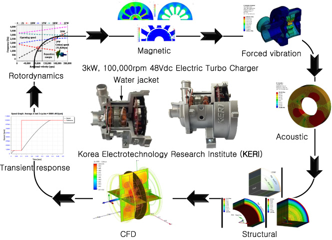
The proposed electric turbo charger with mulit-physics analyses.
Figure 2 shows flux density, core loss, eddy current loss distribution of the designed PMSM using 2-D FEA by Jmag and Ansys Maxwell V18.1. It has surface permanent magnet type rotor and consists of 2 poles and 12 slots. This paper deals with analyzing parameters to reduce iron loss and eddy current loss which occur prominently at high speed. The electric performance analyses are validated according to core material for high speed (POSCO, 20PNF1500). Steady-state and transient CFD are performed considering all losses. The electric performance such as the average torque, the losses, the efficiency flux density distribution, core & eddy loss distribution result of proposed model are shown in Table 1 and Fig. 2.
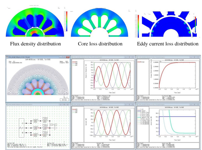
Magnetic performance analysis results of the proposed model.
The forced vibration analysis was conducted by importing the magnetic forces applied to each tooth shown in Fig. 3. An acoustic analysis was also done by importing the vibration velocity on the intersection surface between the structure and the fluid, which in this case is considered to be air, as shown in Fig. 5. Figure 4 shows frequency response result and forced vibration mode according to the pole passing frequency and resonance frequency. The exciting frequency, pole passing frequency (f
pole passing
) is as follows:
The electric performance results of proposed model (sin current waveform)
Figure 4 shows the forced vibration response results on the surface of motor housing according to the pole passing exciting frequency. The Bode plot which consists of amplitude and phase angle of the vibration velocity response is shown according to three translational directions. The amplitudes at the resonance frequencies are larger than pole passing frequency and around that. Acoustic analysis are performed and A weighted Sound Pressure Level (SPL) response of the proposed SPM-type synchronous motor are shown in Fig. 5. A magnetic-forced vibration-acoustic analysis is performed by Ansys Multiphysics (V18).
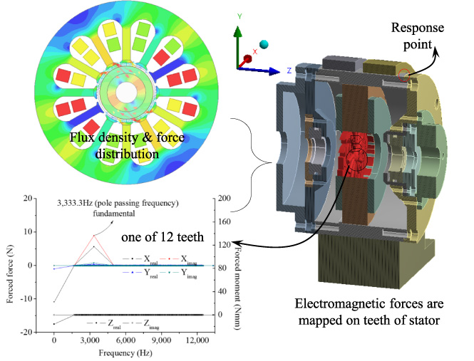
Excited forces and moments are applied on the teeth of stator.
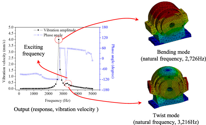
Forced vibration mode and response of the proposed SPM-type synchronous motor.
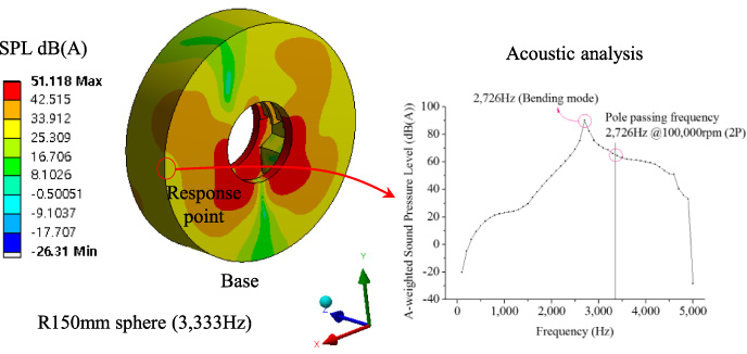
Acoustic analysis and SPL response of the proposed SPM-type synchronous motor.
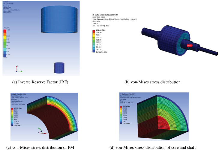
Failure analysis and von-Mises stress analysis considering centrifugal force and temperature (100,000 rpm and 120 °C).
CFRP failure analysis is well performed by the 3D rotor model using Ansys Composite Prepost (ACP) module. Figure 6 shows the inverse reserve factor (IRF) result. If IRF index is bigger than one, it is close to be failure. However, IRF index is smaller than one, it is close to be safe.
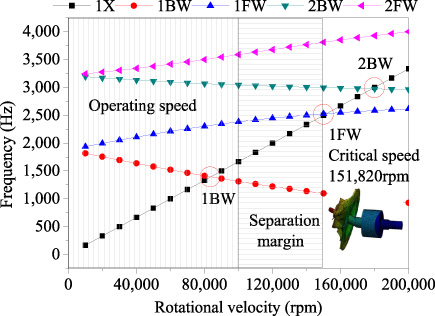
Campbell diagram.
Therefore, CFRP to protect permanent magnet is stable within maximum 0.25. Also, CFRP of magnetic encoder is stable within maximum 0.125. Figure 6(b) shows von-Mises stress distribution by centrifugal force and eccentricity. Figure 6(c), (d) show von-Mises stress of PM, core and shaft. CFRP protects PM which is affected by centrifugal force and it is safe because it is generated within the allowable stress of the material used.
Rotordynamic analysis is well performed by the 3D rotor model using Ansys dynamic module. The critical speed of the developed rotor with revised impeller considering the rotation and gyroscopic effects should be above the operating speed, 100,000 rpm, and should have a sufficient separation margin, 52%, as shown in Fig. 7. There is no critical speed in the operating speed range. The critical speed of the rotor should exceed the operating speed (100,000 rpm). An appropriate separation margin is typically at least 20% considering API (American Petroleum Institute) standard 610 [2]. Bearings are applied to steel ball deep grooves in consideration of the cost-effectiveness.
The used material and heat source for Computational Fluid Dynamics (CFD) [100% sin current waveform]
The used material and heat source for Computational Fluid Dynamics (CFD) [100% sin current waveform]
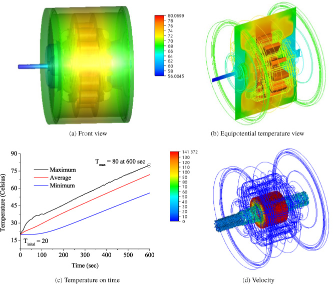
Transient CFD temperature results (3 kW, 100,000 rpm, 100% current load, 10 minutes).
A high-speed motor and controller for ETC applications are important to shorten response time, to within 0.5 s, considering the thermal stability and current overload rates. The response time depends on the controller that must be over current for the ETC. Computational Fluid Dynamics (CFD) analysis is divided by transient analysis and steady-state one. Steady-state and transient CFD analyses were performed using the Autodesk CFD SW. Table 2 shows the used material of thermal properties and heat source obtained by magnetic analysis. Transient CFD analysis enables temperature analysis over time. However Steady-state CFD analysis enables saturated temperature analysis without regard to time [5,6]. ETC intermittently used in a low speed and in accelerating intervals. Transient CFD analysis result represents about maximum 80 celsius within 10 minutes at the rated point (3 kW, 100,000 rpm) as shown in Fig. 8. Response time can be found to vary with torque (current) overload rate and current overload rates should be considered between 175% and 200% in order to satisfy development goal of 0.45 s. Three cases (100%, 150%, 200% overload rate) are considered. Table 3 shows the loss analysis results by magnetic analysis according to overload rate (100%–200%). If the drive time of ETC is 10 minutes, the maximum temperature increases up to 114.5 celsius at the 200% overload rate in Fig. 9. Considering the properties of the used material according to the maximum temperature, it has been found that there are no problems with thermal stability. To obtain more thermal stability margin, the forced cooling such as fan and water cooling should be considered.
Loss analysis results according to current overload rates (100%–200%)
Loss analysis results according to current overload rates (100%–200%)
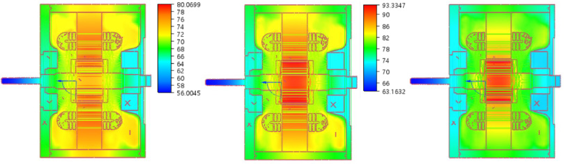
Transient CFD temperature results according to overload rates (100% ∼200%), 10 minutes.
The several performance analyses of a high speed motor, the heart of the ETC, are performed considering multiphysics analyses (magnetic – forced vibration – acoustic – structural – rotordynamics – computational fluid dynamics). This system operates at a power density of 3 kW/kg at 100,000 rpm and is intended to fit into ETC. Loss analysis and transient CFD analysis of the PMSM for ETC applications were performed successfully for thermal stability considering current overload rates.
Footnotes
Acknowledgements
This material is based upon work supported by the Ministry of Trade, Industry & Energy (MOTIE, Korea) under Industrial Technology Innovation Program. [No.10062541, ‘Development of electric compressor to improve low end torque performance and transient performance of 1.6liter grade small diesel engine’].