
Abstract
Finite element method (FEM) of nonlinear magnetic field computation embedded with different vector Jiles-Atherton (J-A) hysteresis models is investigated in this paper. Newton’s method is adopted to do the nonlinear iteration. Both scalar and vector J-A models are incorporated into the FEM computation. The TEAM workshop problem 32 is used as a numerical example. The computed results are compared with the measured ones, which shows the effectiveness of the developed algorithm. The specifics of different vector J-A models are pointed out from the viewpoints of modelling accuracy and convergence performance.
Introduction
To compute nonlinear magnetic fields more precisely, instead of simple B-H curves, hysteresis models are used to construct the constitutive equation of magnetic materials. Jiles-Atherton (J-A) hysteresis model is a popular one, due to its easy implementation and less parameters required [1, 2]. The parameters of J-A model can be obtained by using optimization algorithms to find the optimal values which lead to the global minimal of the objective function [3, 4]. Usually, the electrical steel sheet sample is measured along the rolling direction and the transverse direction. The parameters of J-A model can be obtained from the major hysteresis loops. To investigate the magnetic property of materials under both alternating and rotating excitations, several vector J-A models have been proposed [5, 6]. The modelling accuracies are analyzed for some specific materials [7, 8]. Usually, for the two-dimensional modelling, the parameters of J-A model in rolling and transverse directions are required, and then both isotropic and anisotropic materials can be taken into account. When incorporating the J-A model into the nonlinear magnetic field computation using finite element method (FEM), the inverse J-A hysteresis model is often employed, as the magnetic induction is updated in each nonlinear iteration.
To solve nonlinear magnetic fields, iteration methods, such as Fixed-Point Method, Newton’s Method, are employed [9, 10, 11]. The computation accuracy and efficiency depend on the selected iteration method and the complexity of hysteresis models. In this paper, Newton’s method is employed to do the nonlinear iteration. The Jacobian matrix is calculated according to the differential reluctivity which is obtained from the J-A hysteresis model. The scalar J-A model [2], the derived vector J-A model in [5], and another proposed vector J-A model in [6], are combined into the FEM computation, respectively. The developed program is applied to compute the TEAM problem 32. The computation results are compared with the measured ones.
Field equations
The constitutive law of nonlinear magnetic materials can be represented by the following equation:
where
where
Employing Newton’s method to solve the nonlinear magnetic fields, and applying FEM to the governing equation, result the following system equation:
where
where
To guarantee the convergence of the iteration, the Jacobian matrix must be calculated accurately. Accurate [
where
The TEAM workshop problem 32 described in [12] is taken as the numerical test model. The device is a three-limb ferromagnetic core transformer with two windings of 90 turns placed on external limbs. The core consists of five Fe-Si 0.48 mm thick non-oriented laminations, having conductivity
To get the parameters of J-A model, the major hysteresis loops in the rolling direction and transverse direction are used. The fitness between the measured data and modelling data is set as the objective function. The optimal parameters can be found by using the optimization algorithm to result the minimal objective function value. The obtained parameters of J-A model is shown in Table 1. For the scalar J-A model [2], the vector J-A model proposed in [5], and the vector J-A model used in [6], the two sets of J-A model parameters in Table 1 are applied.
Parameters of J-A model in rolling and transverse directions
Parameters of J-A model in rolling and transverse directions
The TEAM problem 32: Device structure and the pick-up coils (dimension in mm).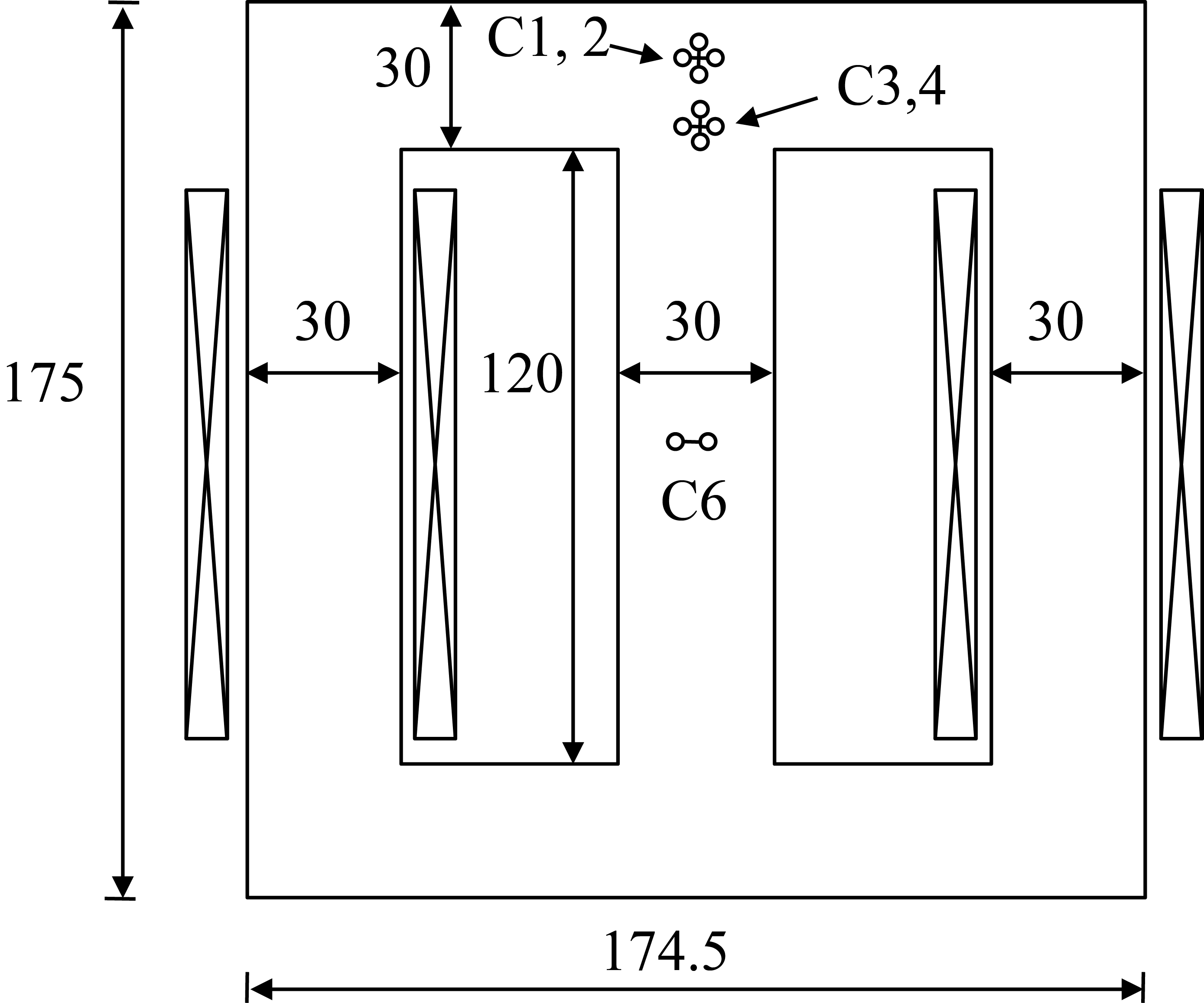
For the two-dimensional modelling, it is natural for the vector J-A models in [5, 6] to be implemented. In the scalar model case, the two dimensional modelling is simplified by using two scalar models in the rolling direction and transverse direction, respectively.
Cases 1 and 3 of TEAM workshop problem 32 are computed by using the developed program, taking account of the scalar J-A model [2], the vector J-A model in [5], and the vector J-A model in [6], respectively. For each case, four periods with 200 steps per time period are computed. For Case 1, the computed magnetic field using different models are compared with the measured data obtained by pick-up coil C6, as shown in Fig. 2. The computed results are almost same, while exist some gap with the measured one. The computed current values match well with the measured one, as shown in Fig. 3. For the Case 1, both of the excitations are in the same phase, and the pick-up coil C6 is in the middle of the central limb. Therefore, alternating magnetic field dominates there. For the J-A models derived in [2, 5, 6], they have almost the same modelling accuracy for alternating excitations along the rolling or transverse directions. The computed results have proven this point.
Computed and measured waveforms of magnetic induction (pick-up coil C6, Case 1).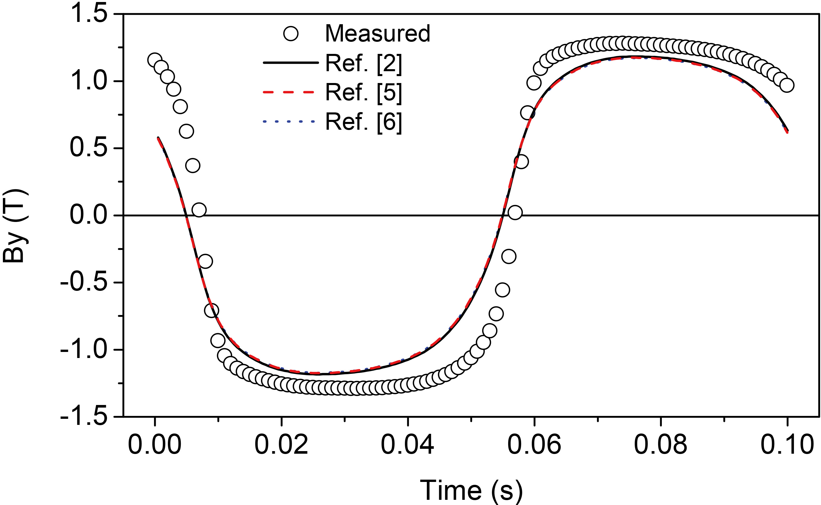
Computed and measured waveforms of current in Case 1.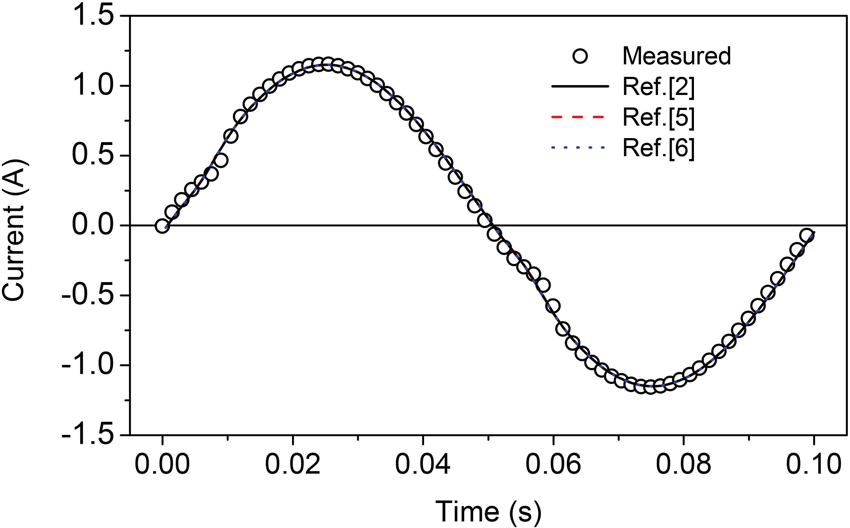
Computed and measured B-loci. (a) Pick-up coils C1 and C2, Case 3. (b) Pick-up coils C3 and C4, Case 3.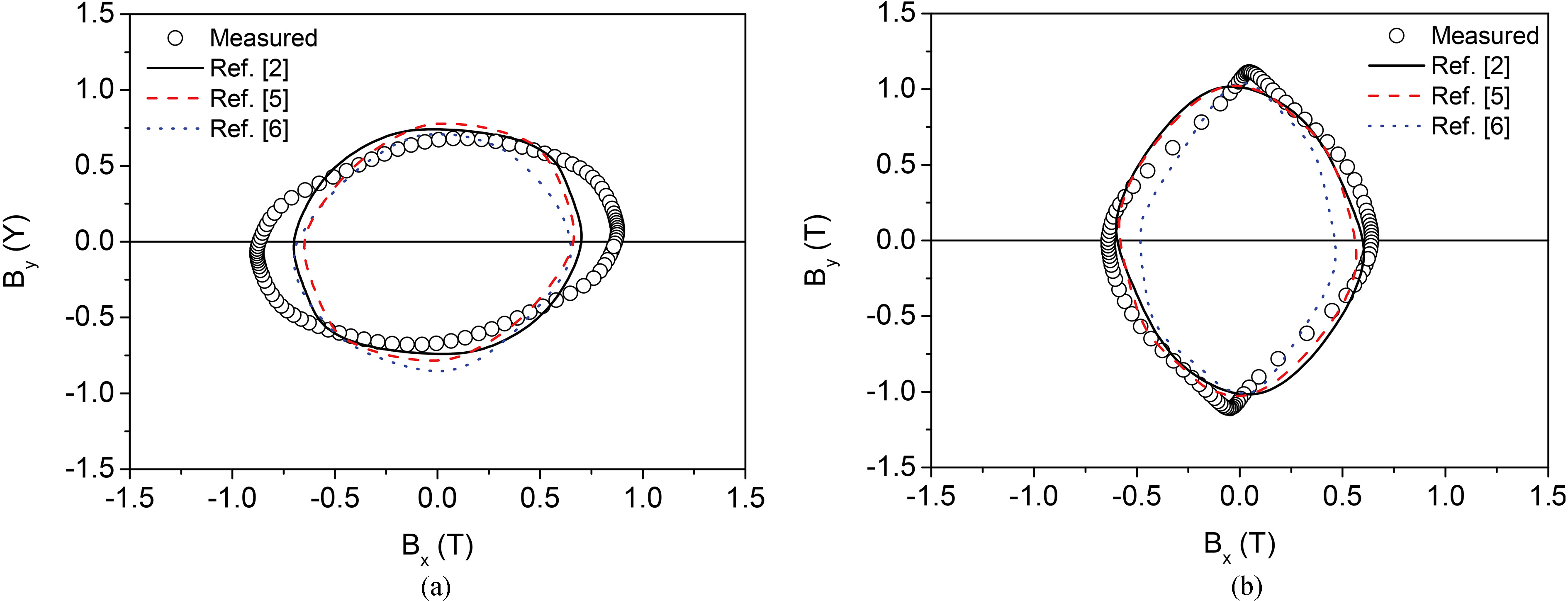
Computed and measured waveforms of current in Case 3.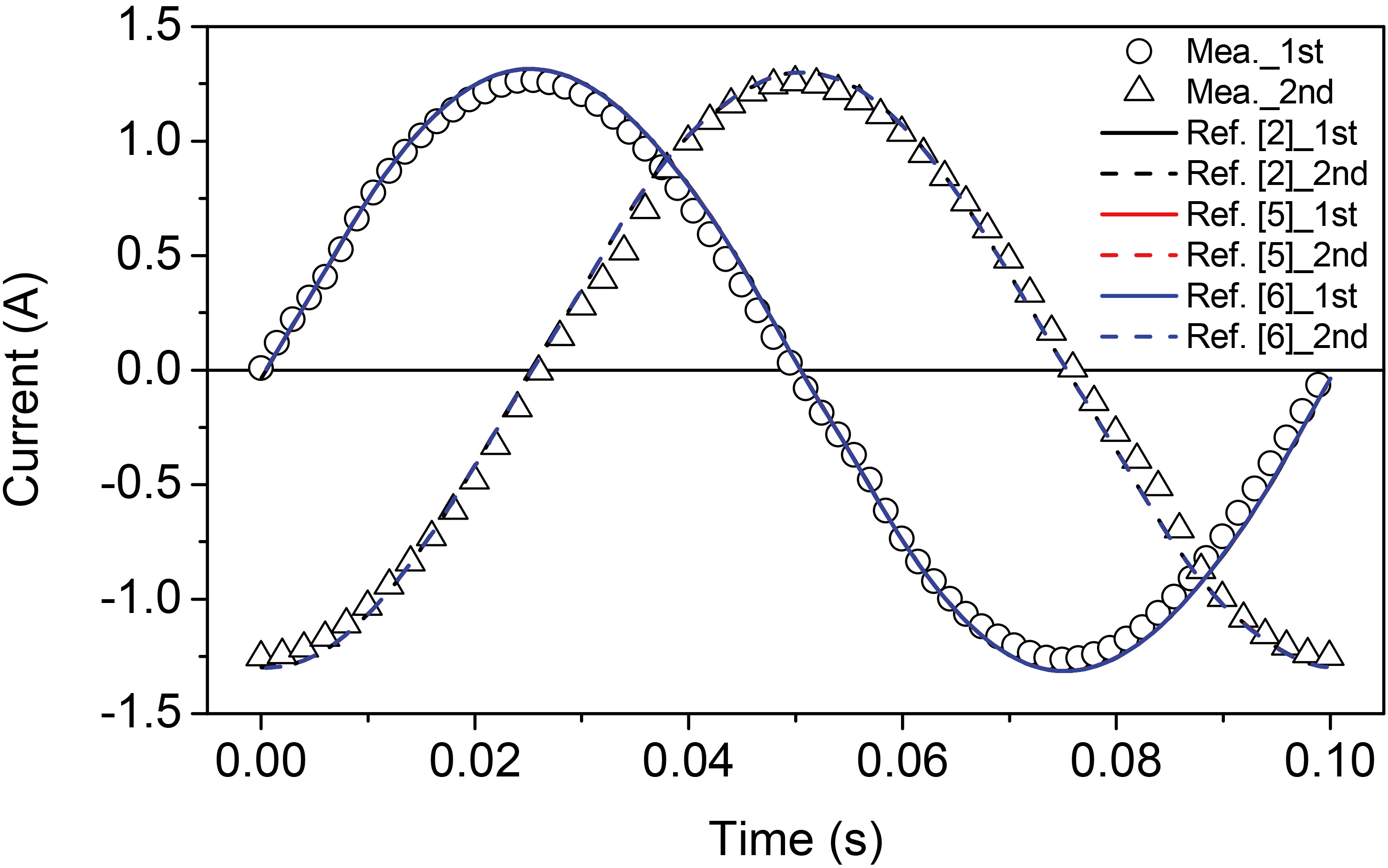
For Case 3, the two windings are fed by voltage sources with a phase shift of 90 degrees. Therefore, rotating magnetic field emerges in the T-joints. The B loci on two points are measured by using the pick-up coils C1 to C4. The Case 3 is also computed by using the developed program. Figure 4 shows the comparison between the computed and measured B-loci on the two points. The computed B loci by different vector J-A models are somewhat different. For modelling the rotating magnetic field, the internal principles of different vector J-A models are different. Generally, the vector J-A model in [6] can take account more of the saturation effect. In the computed case, the material is not deeply saturated. Therefore, the computed gap by using different vector J-A models are not so large. From the viewpoints of computation cost and convergence, the scalar model [2] is the best choice, as the model is not sensitive to the parameters and time step size. For the vector J-A model in [6], for some rotating excitation cases, the modelling results are not smooth enough, which may cause convergence problem, and this situation is also parameters dependent. Figure 5 shows the current waveforms in the two windings. The computed values match well with the measured ones.
Nonlinear magnetic field computations using FEM taking account of different vector J-A models have been investigated in this paper. The TEAM workshop problem 32 is taken as the numerical example. Both alternating and rotating magnetic fields are analyzed. The computation results reflect the features of the hysteresis models. Although gaps exist between the computed and measured results, the computation reflects the hysteresis phenomenon of the materials. The modelling accuracies of different vector hysteresis models are case and material dependent. For unsaturated magnetic fields, any of them can be used, while for saturated situations, the vector J-A model in [6] is preferred in general situation. To obtain a more stable convergence, the models in [2] and [5] are recommended. As materials are not ideally uniform, even for isotropic materials, the hysteresis property in different directions cannot be same. Therefore, it is reasonable there exist some gaps compared with the measured data. For different materials, the modelling accuracies using different vector J-A models may change.
Footnotes
Acknowledgments
This work was supported by the National Natural Science Foundation of China under Grant 51207109, and the Fundamental Research Funds for the Central Universities of China, and the Research Grant Council of the Hong Kong SAR Government under project PolyU 152050/14E.