
Abstract
This paper presents a new design of cycloid corrugated magnetorheological fluid (MR) coupling based on the magnetorheological shear-pressure mixing mode. The device optimizes the formation of the magnetic chain through an arcuate magnetically conductive surface and guides the magnetic circuit with a magnetic isolation ring, so that the mechanical characteristics of the magnetorheological fluid can be fully utilized to enhance the power torque transmission capability. After describing the structure, electromagnetic simulations were performed to verify the formation of magnetically sensitive lines on an arc-shaped surface. The metal rolling force calculation method based on Orowan unit pressure differential equation was used to establish a mechanical mechanism model of a magnetorheological fluid coupling with cycloid corrugated surface. The key parameters affecting the torque transfer performance of the MR coupling were calculated through Matlab software, and the performance of the device was evaluated. After that, the experimental platform was set up to test its performance. The experiment results indicate that the proposed MR coupling performs better than the conventional MR coupling with conventional planes in terms of torque output capability, transmission stability, and impact resistance, while maintaining a feasible magnetic circuit design and a compact structure.
Introduction
In recent years, magnetorheological torque transfer devices (MRTDs) have received wide attention for its advantages in delivering the output torque and reducing the impact on the mechanical rotary transmission [1]. They are better performed than traditional counterparts due to the use of magnetorheological fluid (MRF), which is a smart material with special flow properties. Under the action of external magnetic field, its mechanical properties and damping properties are instantly controllable, and its chemical composition is stable and immune to external environmental factors [2]. With these excellent qualities, magnetorheological fluid is often used as a controllable medium and is packaged in various types of dampers for damping and power transmission [3–5]. In MRTDs, the MRF is operated in a shear mode and encapsulated between a pair of magnetically permeable surfaces that can move with respect to each other. When a magnetic field is applied, the magnetic particles contained in the magnetorheological fluid are aligned along the direction of the magnetic field. They form numerous magnetic chains with magnetic shear stress which impede the relative movement of the structure, thereby achieving the smooth transmission of torque [6].
However, there are two kinds of problems, poor heat dissipation and limited torque output, related to MRTDs such as MR brakes, MR clutches and MR couplings, which prevent them for wide application [7,8]. In order to increase the transmission torque, researchers have made improvements to the structure of MRTDs. Sarkar [9] et al. developed a slotted-disc MR brake with a compression-assisted shear mode, which provides a higher torque value and a better heat dissipation performance than the conventional disc brake. Wu [10] et al. designed a double-layer multi-coil MR fluid brake and analyzed the magnetic circuit and braking torque theoretically. Latha [11] et al. developed a series of multi-disc magneto-rheological clutches for automotive transmission systems, and laid out the detailed design and manufacturing methods. Wang [12] et al. designed a bolt extrusion device which can compress the MR fluid working chamber to enhance the performance of the disc magnetorheological fluid torque transmission. Russo [13] et al. proposed a multi-disc magnetorheological differential that can effectively improve the power transmission performance of automotive transmission systems. Indian scholar Ghavghave [14] et al. developed a spherical magnetorheological braking device that increases the contact area to increase rotational damping. Japanese researchers Kikuchi [15,16] et al. are working on the research of miniature multi-disk magneto-rheological rotation transfer devices and experimentally testing the dynamic and static torque response performance of the developed devices. Based on previous work, Nguyen [17–20] et al. conducted a series of in-depth studies on the dimensional design of different types of magnetorheological torque transfer devices, minimizing the size of the MR torque transmission device.
It can be seen that the above studies tried to improve the torque transfer performance either by increasing the working contact area of magnetorheological fluids or by adding additional devices. These methods will increase the volume and weight of the MRTDs, the manufacturing cost and the structural complexity that could significantly lower the working reliability. Therefore, some researchers began to work on the mechanism of the dynamic transmission of magnetorheological fluids, and considered the improvement in the frame structure of the magneto-rheological torque transmission device. Yu [21] et al. proposed a magneto-rheological system that could effectively improve the torque output in the liquid spiral flow mode. Poznic [22] et al. increased the magneto-intensity of the MR fluid working chamber by optimizing the distribution of magnetic and magnetic materials to boost the utilization efficiency of the magnetorheological fluid. Na Wang [23] tried to change the texture structure of the disc surface of a conventional disc magneto-rheological brake to improve the torque transmission capability.
Their work provides a new direction of endeavors for the improvement that surface texture patterns can affect the torque transferring performance of the MRTDs. In this work, a new design of cycloid corrugated MR coupling based on the magnetorheological shear-pressure mixing mode is proposed. It employs a serpentine magnetic circuit to make the overall structure more compact, which increases the utilization of magnetorheological fluid. Meanwhile, the MR fluid working chamber is designed to be corrugated. The shape of the flux linkage is optimized by the curved magnetic surface, and the magnetic circuit is guided by the isolation ring. With such design, the working mode of the flux linkage changed from the simple shear mode to the squeeze and shear hybrid mode, which can improve the torque transmission capability of the MR coupling.
The rest of this paper is organized as follows. Section 2 provides the structure and working principle of the designed cycloidal corrugated MR coupling. In Section 3, Ansoft software was used to analyze the magnetic circuit design, and the shear-pressure mixing working mechanism of the arc magnetic flux was introduced. Section 4 establishes the torque transmission mathematical model of the coupling under working condition based on Orowan equation. In Section 5, Matlab software was used to simulate and analyze the mathematical model, and the characteristics of the transmission torque of cycloid ripple MR coupling under shear-pressure mixing mode were revealed. In Section 6, a comparative experiment was conducted between the structure designed in this paper and the traditional structure, and the validity of the established mathematical model for the shear-pressure mixing mode was verified. Section 7 concludes the paper.
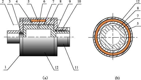
The structure of the designed MR-coupling. 1. Input sleeve, 2. Outlet end, 3. Bearing, 4. Isolation ring, 5. Coil, 6. Isolation ring, 7. MR fluid, 8. Output sleeve, 9. Silicon seal, 10. Bearing, 11. Output cover, 12. Drive sleeve.
The structure of the cycloid corrugated MR coupling is shown in Fig. 1(a). The coupling is mainly composed of two parts that can rotate relative to each other, which are respectively connected to the drive equipment through the input sleeve (1). The drive sleeve (12) and the driven sleeve (8) are connected to the load. The electromagnetic coil (5) is wrapped around the drive sleeve and the outgoing end leads out of the coupling input end from the sub (2), which is connected with the power supply slip ring. The driven sleeve is connected with the drive sleeve through the bearings (3) and (10) installed in the input sleeve and the cover (11). Connected this way, to the driven sleeve can achieve relative rotation and remain in the circumferential and the axial direction. There is a gap (7) serving as the cavity for magnetorheological fluid, and the driving sleeve is sealed by the O-ring (9) to prevent the liquid from leaking. The magnetic isolation made of a magnetic insulating material is embedded inside the inner diameter of the coil along the circumferential direction of the driving sleeve. Rings (4), (6) are used to guide the magnetic circuit. The axial sectional view of the coupling is shown in Fig. 1(b). The outer surface of the driven sleeve is formed into a special cycloidal form through electric discharge machining, and forms a corrugated magneto-rheological fluid chamber with a different type from the driving sleeve. The MRF-132DG magnetorheological fluid from Lord Corporation, USA, is used. It has large adjustable yield stress and wide operating temperature range, which is suitable for occasions with moderate rated power and precise control, and its magnetic saturation shear stress can reach 50 Kpa. The magnetic permeability part is made of Q235 structural steel with good magnetic permeability, and the magnetic separation ring material is made of aluminum alloy.
Figure 2 shows the detailed structure of the coupling, including its power supply and heat dissipation. When a current excitation is present in the electromagnetic coil, the formed magnetic field will pass through the entire magnetically permeable portion of the magnetorheological fluid, which contains a large number of ferromagnetic particles. These particles will form a flux chain with static yield strength under the action of a magnetic field, thereby achieving a flexible connection of the inner and outer rotating parts of the coupling.
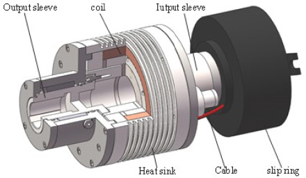
The detail structure of designed MR-coupling.
Since the size of magnetic field and its distribution is crucial to the performance of the magnetorheological fluid coupling, the electromagnetic characteristics of the designed magnetorheological fluid coupling should be evaluated to justify the rationality of the electromagnetic structure design. Therefore, it is highly necessary that the electromagnetic simulation analysis of its magnetic circuit state be conducted.
Coupling magnetic circuit analysis
To effectively transmit the input torque, the magnetic induction line should evenly and perpendicularly pass through the working fluid cavity of the magnetorheological fluid to form a magnetic flux in the magnetic rheological fluid. In order to analyze the pathway of magnetic induction lines in the designed MR coupling, electromagnetic simulation was performed using the finite element software Ansoft. Since the device has an axisymmetric structure, a simplified quarter model can be used to lower the computing time. Table 1 shows the material composition of the main structure. The relative permeability of air and 1Cr18Ni9Ti is set as fixed value 1, while the magnetic permeability of Magnetorheological Fluids and Q235 Steel are assumed B-H Curves. After the material parameters were determined, parallel flux boundary conditions were set and a current was applied to the coil section for analysis. The distribution of 2D magnetic induction lines is shown in Fig. 3.
The main material of the MR coupling
The main material of the MR coupling
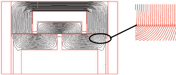
Path of the magnetic induction line (excitation current: 1 A).
It can be seen from Fig. 3 that the magnetic field lines generated by the excitation coils pass vertically through the inner wall of the outer rotation sleeve four times. From the enlarged view on the right side, it can be seen that the magnetic induction line in the effective working area is evenly distributed due to the obstruction of the magnetic isolation ring, which justifies the validity of the magnetic circuit design. The three-dimensional electromagnetic field analysis results are shown in Fig. 4. It can be found that the magnetic induction intensity varies sharply in the circumferential direction on the outer surface of the drum, with the maximum at the peaks and minimum at the troughs. Due to the effect of the magnetic isolation ring, the magnetic induction intensity in the effective working region of the magnetorheological fluid is evenly distributed along the axial direction, which is similar to the two-dimensional electromagnetic simulation.
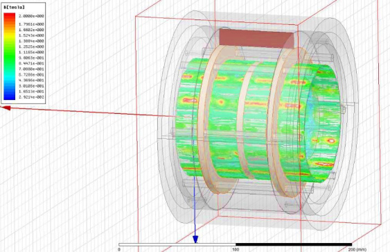
Magnetic field B in the corrugated MRF chamber (1000 Amp turns).
After the simulation completed, the next step is to analyze and calculate the composition of the magnetic circuit. All the variables used in the calculation are shown in Table 2. For convenience, two assumptions are made. First, magnetic flux leakage in the air is negligible. Second, the magnetorheological fluid is evenly distributed in the working chamber. Figure 5 shows the designed magnetic circuit and radial parameters of the coupling. From the preceding magnetic circuit analysis, the following formula can be obtained according to the Ampere loop theorem:
Variables and parameters
It is also known from the properties of the magnetic circuit that the magnetic flux of each segment of the magnetic circuit is equal everywhere. According to Gauss‘s law 𝛷 = B
i
A
i
, then
The B-H curve [24] of MRF132DG from Lord Company is given by the following expression:
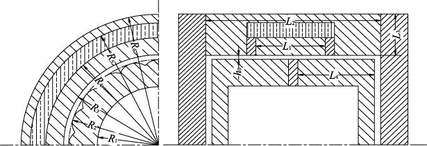
Magnetic path and radial parameters of the designed MR coupling.
The main magnetically conductive parts are made of Q235 steel with good permeability performance, and its B-H curve is as follow:
Then the relationship between the magnetic induction intensity of the MRF and the current in the coil can be described as follow:
The device designed in this paper contains a corrugated magnetorheological fluid working chamber, which itself has a complicated assembly structure and contains more connectors. In this sense, the device is not completely axisymmetric. When the magnetic field passes through the curved surface, its direction and size will change. However, the magnetic line over the arc surface is almost parallel to the surface normal of the magnetic conductor [25].
In order to understand the situation here, the ANSYS electromagnetic simulation module is used. Figure 6 shows the distribution of magnetic induction lines on the arc surface and the planar surface with the same excitation current. As shown in Fig. 6(a) for arc surface, the magnetic induction lines have changed direction obviously, bending toward MRF gap to form arc magnetic chains. On the contrary for planar surface, it can be seen in Fig. 6(b) that the magnetic field distributes uniformly and the direction of the magnetic induction lines is almost perpendicular to the two parallel planes.
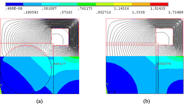
The distribution of magnetic induction line and magnetic induction intensity between the arc surface and the plane under the same current excitation (excitation current 1 A).
According to the properties of MRF, the direction of the magnetic chains which formed by magnetic particles in MRF is consistent with the direction of the magnetic flux. That is to say, when the coil is energized, the magnetic field will make the magnetic particles in MRF align along with the direction of the magnetic flux to form magnetic flux linkage, arc or the other kinds of magnetic chain depending on the surface curvature. When there is a relative rotation between the internal and external rotors, parallel planes will result in the linear magnetic chains that would transfer torque with sheer shear force as shown in Fig. 7(a), while the corrugated surface will lead to arc magnetic chains formed that can transfer the torque with both the shear and squeeze force as shown in Fig. 7(b).
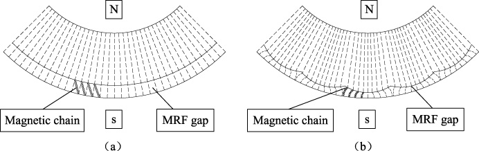
The way in which the magnetic flux blocks relative movement when the flat plate and the corrugated plate rotate in the drum.
The central function of the MRFCs is to achieve smooth, controllable transmission of rotational power. To illustrate the electromagnetic and mechanical properties of the designed device, a mechanical model was established.
Analysis on the force of ripple cavity flux linkage
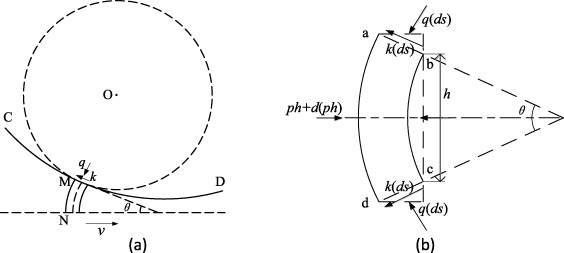
As noted in Section 3, when the rotor with corrugated surface rotates in the outer cylinder, most of the torque is created by a deformation process similar to the movement of rolling workpiece under the effect of rotating rollers. In metal rolling, the Orowan equation is used to calculate the rolling force and its correctness has been verified. Here, when the MR coupling is in operation, the inner and outer rotating portions press the curved surface to form an arc flux linkage and transfer torque. This process is similar to metal extrusion in the rolling. Therefore, the Orowan equation was adopted to correlate the arc flux linkage and torque transfer [26]. This paper uses a block-based deformation force model [27], as shown in Fig. 8.
Deformation stress mechanism model of the proposed method.
As shown in Fig. 8(a), it is assumed that the curved flux element MN and the arc CD are orthogonal to the curvature circle at M. For the convenience of calculation, the micro-element is now expanded into an axisymmetric shape abcd as shown in Fig. 8(b). θ is the angle of the microelement and h is the height of the extended element. The following force equilibrium equation can be obtained:
So Eq. (7) can be rewritten as Eq. (9)
Equation (9) can be simplified to be Eq. (10) by using geometrical relationship
Equation (10) establishes the differential equations of the shear stress k, the positive pressure q and the corrugated shape parameters h and θ. The detail mechanical model of the coupling will be introduced next.
The mechanical model obtained in the previous section is combined with the ripple equation to mathematically describe its transmission torque. This paper selects the epicycloid (outer chord wheel), which is commonly used in engineering applications. Its general parametric equation can be described according to Eq. (11):
Schematic drawing of the epicycloid surface.
As shown in Fig. 9, the epicycloid corrugated surface is now deployed in the circumferential direction. The single cycloid parameter equation can be described by Eq. (12):
When θ is small, tan θ ≈ θ. By using the geometrical relationship:
Differentiating between the two sides of the Eq. (12):
From the boundary conditions: 𝜑 = 0, p = 0 and A is the integral constant.
Equation (16) is now changed to Eq. (18):
The average pressure in the effective area can be expressed as:
Where, 𝜑1, 𝜑2 ∈ (0, π] are the initial and ending angles of the magnetic flux effective area. The unit horizontal force F
d (N/mm) on which the flux acts on a single corrugated surface can be expressed as Eq. (20):
In addition, when the coupling of the magneto-rheological fluid has not reached a steady state during the start and the braking of the transmission, a relative rotational speed difference exists between the inner and outer drums and the magneto-rheological fluid will be stirred during this period. The viscous friction effect of the magnetorheological fluid needs to be considered. In general, the viscosity of a magnetorheological fluid is not in the same order of magnitude as the resistance caused by the magnetically induced yield stress. Due to the fact that the radius of the cycloidal corrugation of the inner cylinder is small relative to the radius of the outer drum, the exit and entrance voids are now equivalent to a general wedge slider and thus the convergence ratio can be defined as:
The unit viscous friction to which the wedge slide is subjected can be expressed as [28]
So viscous resistance torque can be written as:
The total transmission torque is:
In addition, the general transmission torque of an ordinary planar magnetorheological torque transmission device can be expressed as [29]:
The right side of the above formula is the magneto-rheological shear force of the magnetorheological fluid and the torque generated by its own viscosity. For a high-power magnetorheological fluid torque transmission device, the torque resistance generated by the mechanical frictional force originates from the frictional resistance of the bearing roller and is generally negligible.
Following the electromagnetic model and torque transfer mechanical model established in the previous section, this section evaluates the performance of the designed MR coupling by simulating the mathematical model with Matlab. The performance was appraised in terms of the maximum transmission output torque, viscous drag characteristics and torque adjustability. The influence of the key ripple parameters on the output torque of the coupling was analyzed, and the design parameters of the prototype were determined.
The maximum transmission output torque of MR-coupling
The maximum output torque of the MR-coupling T max is defined as the maximum transmission torque before the relative rotation between the inner and outer drums when the magnetorheological fluid reaches the magnetic saturation state (saturation means full). It directly reflects the bearing capacity of the MR coupling. According to the analysis in the previous section, the minimum clearance h min, inner drum radius R 2, and rounding radius r are the key parameters affecting the torque transfer. In the following, the effect of these parameters on the maximum output torque is discussed through a variable parameter method. Set the effective length L of the inner drum to 100 mm when calculating the simulation.
Figure 10 shows the variation curves of the output torque T of the cycloidal corrugated MR coupling and the ordinary planar MR coupling with the minimum clearance h min under the four different inner-radius parameters. According to the simulation results, when the rounding radius r is 2 mm and 5 mm respectively, the maximum transmission torque of the cycloidal corrugated MR coupling is approximately 1.1 to 1.6 times that of the conventional cartridge MR coupling. Therefore, the rounding radius r should not be too large. Otherwise, the magnetic field will be unevenly distributed, resulting in low output torque. Moreover, when the minimum clearance h min does not exceed 1 mm, the maximum output torque performance of the MR coupling proposed in this paper has been significantly improved.
The maximum transmission torque changes with the key dimensions.
If the base circle radius and rounding radius exactly divides and divides, then a single cycloid arc exactly covered the base circle, each cycloid ripple roll angle is the largest expansion, that is, then the ripple at this time the least number, marked as n = n
min, then r = r
min. Here, the magnetic field intensity rapidly decreases and the effective number of flux chains decreases, which greatly reduces the torque transfer efficiency of the magnetorheological fluid. Therefore, in order to avoid the above situation, the number of ripples
(1) By decreasing the base circle radius Ro and increasing the rounding radius r, as shown in Fig. 11.
The maximum reduction clearance by increasing the radius of the circle.
(2) By increasing the number of ripples n, as shown in Fig. 12.
The maximum gap reduction by increasing the number of corrugations.
Figure 13 shows the output transfer torque of a cycloidal corrugated magnetorheological fluid coupling with the number of ripples n and the rounding radius r under different excitation currents (in ampere-turns). It can be concluded that as the number of ripples or rounding radius increases, the transmission torque reaches a maximum at a certain value, and the value of the base circle expansion angle 𝜑 is between π∕2 and π. However, as the number of ripples and the rounding radius continue to increase, the transmission torque begins to decrease. This is because when the number of ripples or the rounding radius increases to infinity, the maximum gap h max becomes 0 mm. In other words, the outer surface of the inner tube will tend to be a normal plane, and the torque transmission performance of the corrugated MR coupling will be close to that of a conventional planar MR coupling. It can be seen that a reasonable number of corrugations and rounding radius are critical to the torque transmission performance of corrugated MR couplings.
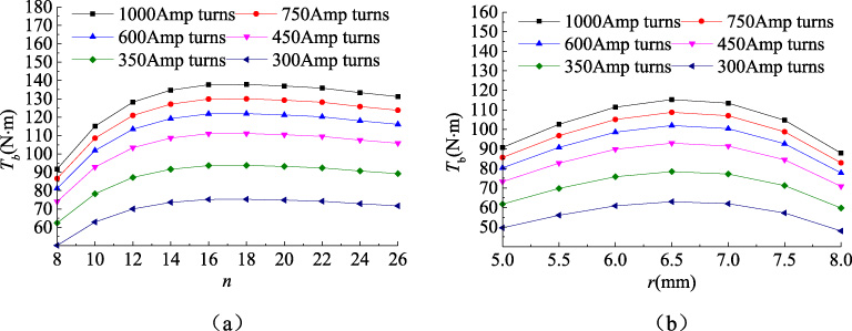
The relationship between the transmission torque and the number of corrugations n (a) and the radius r (b) under different excitation currents.
Before the MR coupling enters into a stable working state, there is a relative rotation between the inner and outer drums, and thus the viscosity of the magneto-rheological fluid can affect the torque transmission. Therefore, it is necessary to analyze the damping caused by the viscosity of the magnetorheological fluid. Substituting the relevant design parameters, the viscous drag moments of the two magnetorheological fluid couplings are simulated by varying some key parameters. The simulation results are shown in Fig. 14.
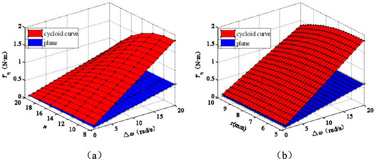
The relationship between the viscous resistance moment and the number of corrugations n (a) and the rounded radius r (b).
It can be seen that the viscous drag torque of the designed MR coupling increases with the number of ripples n and the rounding radius r. After reaching the maximum value, it gradually decreases and approaches a constant. The viscous drag torque is slightly larger than that of the regular plane, but it is not much different.
The torque adjustability 𝜑 is defined as the ratio of the maximum transmission torque T
max
of the MR coupling in the stable working state to the transmission torque T
𝜂 in the non-stable working state. It is used to evaluate the controllability of the torque transmission process. Set the torque adjustability of the two MR couplings as 𝜙
b
and 𝜙
p
, and the expression can be expressed as:
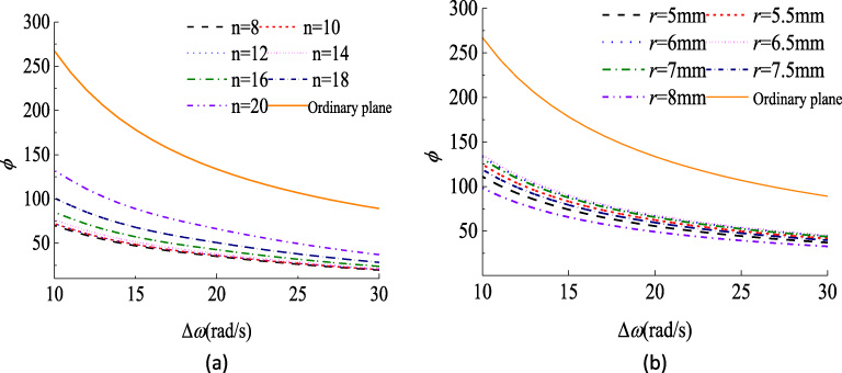
The relationship between the torque adjustable ratio and the inner/outer cylinder rotational speed difference.
Based on the above simulation and analysis, the structural dimensions of the magnetorheological fluid coupling are determined, which is shown in Table 3. In addition, the minimum clearance h min of the experimental prototype was set to 1 mm.
The structural size of the designed MR coupling
According to the previous analysis of this paper, a cycloidal corrugated MR coupling experimental prototype was designed and custom made. The comparative experiment was conducted between the structure designed here and the traditional structure, and the rationality of the established mathematical model for the shear-pressure mixing mode was verified. After survey, The MRF-132DG magnetorheological fluid was selected for experiments. Because its viscosity and ferromagnetic particle content are very suitable for MR couplings devices compared to other types of magnetorheological fluids.
Figure 16 shows the structure of the test device, which is composed of a servo motor, a MR coupling, a torque and speed sensor, a reduction gear box, a load flywheel, and a magnetic powder brake. Each transmission part is connected by a rigid coupling. The active and slave cylinders of the MR coupling are respectively connected with the output of the servo motor of the test stand and the reduction gear box. By clicking the servo drive, the working speed and input torque of the coupling can be adjusted. The DC power supply can adjust the excitation current of the magnetorheological fluid coupling. The torque and speed sensors detect the speed and torque at both ends of the coupling as well as the load. The sensor used in the experiment is the JN338 intelligent digital torque speed sensor manufactured by Beijing Sanjing Startup Co., Ltd., which can measure torque and rotational speed simultaneously. The measurement range of the sensor is 0--4000 rpm/0--500 N ⋅ m and the measurement accuracy of the sensor is 1%. Therefore, the resolution of the speed sensor and the torque sensor are respectively 4 rpm and 0.5 N ⋅ m, respectively.
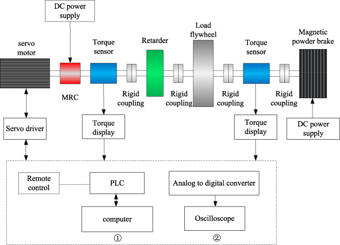
The schematic diagram of the test system.
Figure 17(a) shows the test prototype. Two kinds of inner drums, as shown in Fig. 17(b) are used to perform the comparative test. Screw connection is used as the main connection form of the inner and outer drums so that repeated assembly is possible. The static seal uses O-rings made of silicon rubber and is uniformly coated with a heat-resistant adhesive at the bolted joint of the working fluid chamber. The dynamic seal uses the silicone rubber and polytetrafluoroethylene, so as to achieve a good sealing effect while reducing friction loss. Magnetic isolation ring to guide the magnetic lines is made of aluminum alloy. Half couplings and connecting bolts are all austenitic stainless steel to prevent leakage of magnetic lines. The window area of the excitation coil is 700 mm2, and the winding number of a 155-gauge copper enameled wire with a diameter of 0.8 mm is around 700 turns. The resistance is about 12.5 Ω, and the outer diameter is 180 mm. The total length of the device is 21 m, and the number of cycloidal ripples on the outer surface of the inner drum is 14.
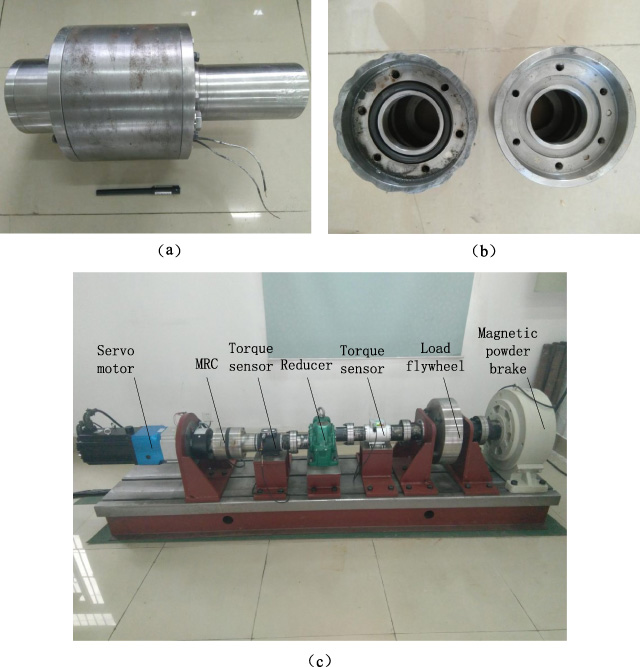
Industrial inertia test system of Magnetorheological Fluid Coupling with Cycloid Corrugate Surface. (a) Magnetorheological fluid coupling (b) Inside rotary drum (c) The full view of the test bed.
The main experimental items are as follows:
(1) Static transmission (braking) torque test. It tests the braking ability of the MR coupling during motor braking caused by a rotational speed difference between the input and the output.
The magnetic powder brake is first put into the maximum current load to ensure that the load of the test stand is fully braked. A certain current is energized to the magnetorheological fluid coupling, and then the motor is started. When the input speed is stable, the torque/speed sensor output of the magnetorheological fluid coupling is recorded at different input speeds.
Figure 18 shows the experimental results, in which Fig. 18(a) is the test result of the regular plane MR coupling, and Fig. 18(b) is the test result of the cycloidal corrugated MR coupling. From the test results, it can be seen that when the excitation current gradually increases from 0 to 1 A, the torque increase is approximately linear. After the excitation current exceeds 1 A, the increase rate decreases significantly. Compared to regular plane couplings, the torque of the couplings proposed in this paper is still able to increase under large currents. When the magnetorheological fluid saturates, the maximum braking torque increases by approximately 12.5%.
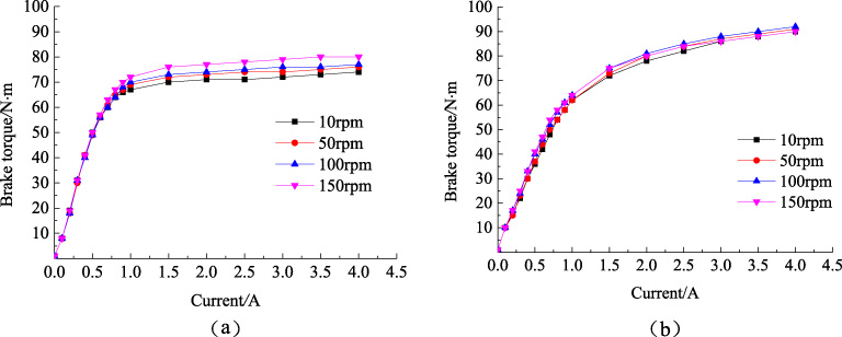
The static transmission (braking) torque of the designed MR coupling at different excitation currents.
(2) Dynamic transmission torque test. It tests the stability of the torque transmission of the MR coupling under normal working conditions. In addition, it can measure the maximum transmission torque of the device.
First, a certain current excitation to the MR coupling is input and the motor to runs with a certain speed. Then, the magnetic powder brake is slowly loaded until the torque/speed sensor output of the MR coupling output shows a slip, indicating the structure is in stable working state. The change of the sensor’s value over time is recorded.
It is found that as the load increases, the dynamic transmission torque of the MR coupling continues to increase, exceeding the static transmission (brake) torque and decreasing after reaching the maximum value. The dynamic transmission torque of the two MR coupling at different excitation currents is shown in Fig. 19. Figure 18(a) is the test result of the ordinary plane MR coupling, and Fig. 18(b) is the test result of the cycloidal corrugated MR coupling recommended by this paper. It can be concluded that as the load increases, the dynamic transmission torque of the MR coupling continues to increase and exceeds the static transmission (brake) torque, eventually reaching the maximum transmission torque. If the load is further increased at this time, the output torque rapidly decreases to the value of the static transmission (brake) torque.
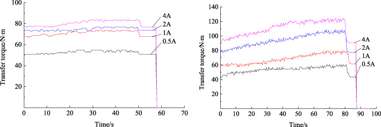
The dynamic transmission torque of the designed MR coupling at different excitation currents.
This can be explained by the “wall effect” [30]: when there is a forced relative movement between the input and output parts of the magneto-rheological torque transmission device, part of the flux linkage and the surface of the metal structure will slip without yielding, resulting in a output torque lower than the theoretically calculated value. Unlike the MR braking and MR clutches, there is no forced relative movement of the input and output parts of the MR coupling during dynamic torque transmission. At this time, because the static friction force of the metal surface is larger than the sliding friction force, the maximum torque that can be transmitted is close to the transmission torque when the flux linkage yields and reaches the theoretical calculation value. By comparison, it is found that the maximum dynamic transfer of the MR coupling designed here is larger than that of the regular planar MR coupling.
Figure 20 shows the curve of maximum transfer torque for two surface MR couplings at different excitation currents. It can be seen that he maximum transmission torque of the coupling proposed here increases by about 20% in comparison with the regular plane MR coupling, and the test result is very close to the theoretical calculation.
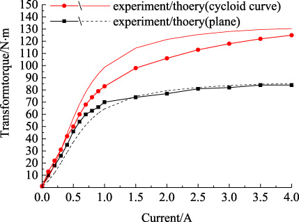
Comparison of the dynamic transmission torque of the designed MR coupling and Ordinary plane MR coupling.
(3) Viscous resistance torque test. It tests the magnitude of the resistance torque caused by the viscosity of the magnetorheological fluid when the magneto-rheological coupling had no applied excitation current and there was a rotational speed difference between the input and output.
The test results are shown in Fig. 21. According to the test results, the viscous drag torque of the coupling designed in this paper is always larger than that of the regular plane MR coupling, but the difference is not large. In addition, the trend of change is consistent with the theoretical analysis. The viscous drag torque has a significant increase when the rotational speed difference increases. Due to the frictional resistance, the measured value is larger than the theoretical calculation.
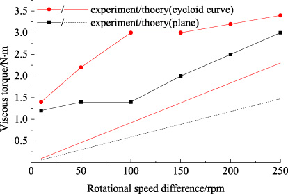
The viscous torque of the designed MR coupling at different rotational speed differences.
(4) Impact damping characteristics test. It tests the damping characteristics of the MR couplings when the motor is started and stopped under different excitation currents.
First, the magnetorheological fluid coupling was excited with a certain current, and a small current load will transfer to the magnetic powder brake. The motor is then started and stopped immediately after the motor reaches a stable speed to simulate the instantaneous start and stop of the drive system. Record the torque of the output of the MR coupling during the entire period as a function of time. The experimental results are shown in Fig. 22 in which Fig. 22(a) is the test result of the ordinary plane MR coupling, and Fig. 22(b) is the test result of the cycloidal corrugated MR coupling.
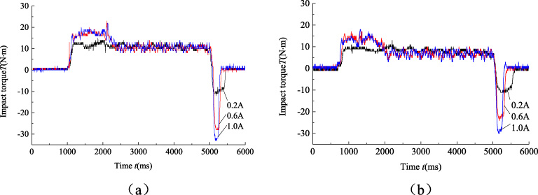
Comparison of the Impact torque of the designed MR coupling and Ordinary plane MR coupling.
As mentioned in the previous section, magneto-rheological devices have excellent damping properties and can be used as dampers. Therefore, the MR coupling can also be used as a rotary damper, which greatly reduces the impact load to protect the equipment during the start and stop of the motor.
From the test results, it is found that as the current increases, the peak value of the impact torque during the period from the start to the stop of the motor becomes larger, but the impact time becomes shorter. Compared to regular plane MR couplings, the MR couplings proposed have a longer impact time under the same current excitation but better damping effect.
This paper presents a systematic investigation, including innovative designing, electromagnetic simulation, theoretical analysis and experimental study of a novel MR coupling with cycloid corrugated surface. The following conclusions can be drawn:
(1) The theoretical calculation results indicate that the transfer torque of the MR coupling proposed in this paper is closely related to the ripple parameters. With the increase of the number of corrugations or the radius of the cycloidal circle, the magnetically transmitted torque increases and approaches a constant value, and the target transmission torque can be flexibly adjusted by changing the ripple parameter.
(2) The experiment results indicate that when the magnetorheological fluid is nearly saturated, the maximum transmission torque of the MR coupling proposed in this paper is approximately 20% higher than that of the conventional planar MR coupling under the same external dimensions. In addition, under the same current excitation, the MR coupling shows much better transmission stability and impact resistance that that of the conventional one.
Footnotes
Acknowledgements
This research was funded by the China National Science Foundation (Project no. 51275369) and National Science and Technology Supporting Program (Project no. 2015BAF06B05).Their supports are gratefully acknowledged.