






Abstract
We propose a novel dual air-gaps and liquid-cooled eddy current retarder (ECR) based upon observing the (1) heat fade of the continuous braking and (2) large rotor weight of the traditional ECR for heavy vehicles. The new ECR maintains a low working temperature because of the liquid cooling stator structure. The eddy current distribution and braking torque characteristic curves are obtained by finite element method (FEM). Combining with 3-D FEM, Kriging approximation model is employed to optimize the structural parameters of rotor tooth. Based on the optimization method, the number of rotor teeth is determined to be 12. The braking torque increases by 14.8% after optimization and the rotor tooth weight decreases by 9.5%, which reduces the adverse influence on the vehicle transmission system. The bench test was carried out to verify the optimized calculation results and the braking torque can be stepless controlled by adjusting the excitation current. Compared with traditional ECR, the dual air-gaps and liquid-cooled ECR has better continuous braking performance and is more suitable for heavy vehicle auxiliary braking.
Introduction
The auxiliary braking device has been applied to buses or heavy vehicles widely. It can decrease the friction plate wearing and improve driving safety because of the contactless braking [1,2]. The eddy current retarder (ECR) and hydraulic retarder are the main types of auxiliary braking device, which convert the vehicle kinetic energy into heat energy by electro-magnetic or hydraulic coupling principle respectively [3]. The ECR has many advantages, such as simple structure, fast response, low cost, and excellent performance at low speed, but there is a serious heat fade because of high temperature [4]. Although hydraulic retarder has light weight and low working temperature, its structure is complex and response is slow [5].
Liquid cooling can make the ECR maintain a low working temperature, but the new structure must be innovative design. The novel liquid-cooled retarders, including permanent magnet retarder [6], dual salient poles ECR [7], and self-excited ECR [8], have achieved good application effect. However, they have the disadvantages of difficult control, large rotor weight and complex structure respectively, as well as no structural optimization has been carried out. The 3-D finite element method (FEM) using experimental design method [9] or single factor analysis [10] is better suited for geometric optimization where end effects are non-negligible such as eddy-current brakes in particular. However, the 3-D FEM is computationally expensive in terms of computer hardware and time. Some analytical or semi-analytical methods are employed to optimize the structure of electromagnetic device with relatively regular shape such as eddy current couplers. In [11], the method of deducing 3-D torque calculations from 2-D FE results and considering end-effects is used to optimize radial-flux permanent magnet eddy current couplers. The simple analytical model combined with the magnetic equivalent circuit (MEC) techniques is developed for design optimization of permanent-magnet eddy-current couplers [12,13].
A novel dual air-gaps and liquid-cooled eddy current retarder is proposed in this paper to solve above problems, and the structural optimization of rotor tooth is carried out by combining FEM and Kriging approximation model. The number of rotor teeth is determined according to the general rotational speed of heavy vehicles. The braking torque test and response characteristic between traditional and new ECRs was studied. We believe that the dual air-gaps and liquid-cooled ECR is applicable to heavy vehicle auxiliary braking. In addition, some possible problems, such as coil temperature rise, existed in the new ECR and the structural optimization including stator will be performed in the further studies.
Structure and working principle
The structure and magnetic circuit of traditional ECR are shown in Fig. 1. Several individual coils are assembled on the salient poles of the stator. When direct current is applied to the coil, a magnetic circuit is formed between adjacent poles. The rotor with heat dissipation fins rotates along the driveshaft. When the ECR works, a great amount of heat is difficult to remove in a short time by forced air-cooled convection. The high temperature will lead to a poor braking performance. The results of bench test showed that the working temperature reaches above 500 °C in 10 minutes and the heat fade is about 40% [14].
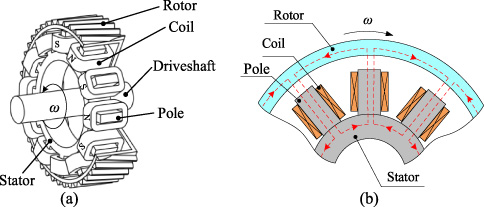
Traditional ECR. (a) Structure. (b) Magnetic circuit.
Figure 2(a) shows the new dual air-gaps and liquid-cooled ECR, which consists of a rotor, a stator, and an integrated excitation coil. The rotor is composed of several rotor teeth and a connecting part. The stator has an inside coolant channel, and its outer surface has a coolant inlet and outlet. The rotor teeth form the dual air-gaps with the inner and outer working surfaces of the stator, respectively. The excitation coil is fixed in the stator to generate the air-gap magnetic flux. The structure of dual air-gaps can reduce the weight and moment of inertia of the rotor under the limited assembly space. The magnetic circuit is shown in Fig. 2(b). The primary flux 𝛷δ passes through the stator, the outer air-gap, the rotor teeth, and the inner air-gap. A little leakage flux
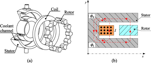
Dual air-gaps and liquid-cooled ECR. (a) Structure. (b) Magnetic circuit.
In the electromagnetic model of ECR, the displacement current in the stator is neglected. Maxwell equations can be expressed as
The magnetic vector potential
The flux density
Then, the braking torque T can be calculated by
The permeability of the stator material (Steel 20) is nonlinear, and the B-H curve is shown in Fig. 3. The conductivity decreases with the increase of temperature, as shown in Fig. 4. Moreover, the transverse edge effect should be taken into account. Therefore, we apply the three-dimensional (3-D) transient FEM to get more accurate results [16,17].
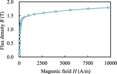
B-H curve of stator material.
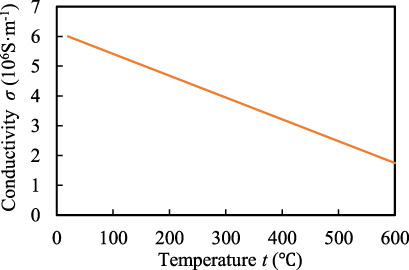
Conductivity of stator material.
The 3-D electromagnetic model of dual air-gaps and liquid-cooled ECR for FEM is shown in Fig. 5. The model is based on the following assumptions: (1) only 1/12 of the entire region is considered because of the periodical symmetry condition. (2) The parts that do not affect the magnetic circuit are omitted, such as the connecting part of the rotor teeth and the driveshaft. The main structural dimensions are shown in Table 1.
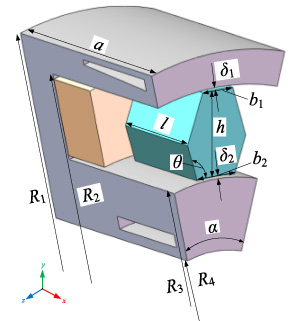
3-D electromagnetic model of the ECR.
Main dimensions of electromagnetic model
Figure 6(a) shows the vector plot of the static magnetic flux density. The dimensions of the stator should be designed to avoid magnetic saturation, while the air-gaps on the rotor tooth require high magnetic saturation. The flux densities of the inner and outer air-gap are respectively 1.65 T, and 1.81 T. Figure 6(b) shows the eddy-current density when the rotational speed of the rotor is 500 r/min, and the excitation current is 100 A. As shown in Figs 6(c) and (d), the eddy-currents are mainly focus on the position facing to the rotor teeth, and the directions of eddy-currents of the two working surfaces are the same. The outer surface has the larger eddy-current density due to the smaller air-gap length.
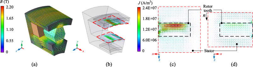
Simulation results of electromagnetic field. (a) Flux density distribution. (b) Eddy current distribution. (c) Vector current of the outer surface. (d) Vector current of the inner surface.
Braking torque and rotor weight are important parameters to evaluate the retarder performance. For the dual air-gaps and liquid-cooled ECR, the structural parameters of the rotor tooth directly influence the air-gap flux density and braking torque. Moreover, the decrease of the rotor weight with high rotational speed is good for the vehicle transmission system. At first, the structural parameters of rotor tooth are optimized by combining FEM and Kriging approximation model. Then, the brake torque curves versus the number of rotor teeth at different rotational speeds are obtained. Finally, the optimum number of teeth is determined based on the general rotational speed of heavy vehicle.
Optimization of rotor tooth structural parameters
Figure 7 shows the optimization flow chart of the rotor tooth structural parameters.
The optimization objectives are to increase the braking torque T (
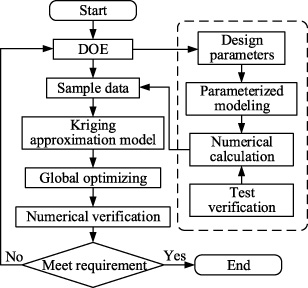
Flow chart of optimization design.
Range of design parameters
The Latin hypercube sampling (LHS) method [18] is used to select sample points from the value ranges of design parameters. The response value is obtained through numerical calculation, which is the sample data of the approximate model. Based on the sample data, the influence of design parameters on braking torque and rotor tooth weight is analyzed. Figure 8 shows the variation of the braking torque with the design parameters. Within the value ranges, the braking torque T has a single peak. Taking the tooth height h as an example to make a qualitative analysis, the braking torque increases as the flux leakage reduces when the tooth height is increasing. However, as the tooth height further increasing, the braking torque decreases because of the increased magnetic reluctance. Therefore, the braking torque has a maximum value when the tooth height is optimum value. But the optimization completely by 3-D FEM calculation is time-consuming.

Variation of braking torque with design parameters.
The optimization method based on Kriging approximate model [19] can effectively reduce the calculation cost and improve efficiency. The Kriging approximation model is better for nonlinear problems and more suitable for optimization design based on computer simulation than other optimum methods. The model consists of two parts, polynomial and random distribution, and its expression is
The sensitivity of the optimization objectives with respect to some design parameters is carried out, as shown in Fig. 9. The braking torque has a nonlinear relationship with the design parameters and is influenced by other design parameters. For example, when the tooth length is at different levels, the relationship between braking torque and tooth height is also changing. However, there is a positive correlation between rotor tooth weight and design parameters.
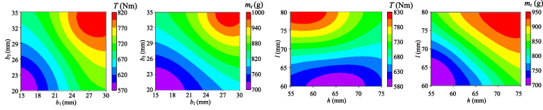
Sensitivity of T (
Figure 10 shows the optimal solution set that satisfies the constraint conditions. It can be seen that the braking torque and rotor tooth weight are mutually restricted. The optimal design parameters are selected according to the requirements of braking performance and actual installation conditions. Table 3 shows the comparison of the design parameters before and after optimization.
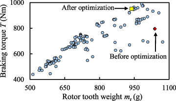
Optimal solution set distribution.
Comparison of design parameters
The optimized parameters are calculated by FEM, and the comparison of the optimization objectives is shown in Table 4. The relative error between the braking torque obtained by FEM, and approximate model method is 1.4%, which can meet the precision requirement. The braking torque increases by 14.8%, and the rotor tooth weight decreases by 9.5%.
Comparison of optimization objective results
The influence of the number q of the rotor teeth on braking torque T is analyzed by the parametric method. For different number of rotor teeth, the structural parameters are optimized using Kriging approximation model method. To make sure that the braking torque is only related to the rotor teeth number, the magnetic flux passing the rotor teeth and the air-gap flux density at the corresponding position should be approximately equal. We choose several reasonable numbers of rotor teeth. Figure 11 shows the relationship between the braking torque and the number of the rotor teeth at different speeds. The braking torque decreases with the increase of the teeth number at low speed (0 to 500 r/min). As the speed increases, the braking torque increases first and then decreases. Nevertheless, the braking torque increases with the increase of the teeth number at high speed (1500 to 2000 r/min). The reason is that the skin effect and magneto-motive force of the eddy-current are both factors affecting the braking torque. The skin depth Δ is calculated by
750 to 1500 r/min is the general rotational speed of heavy vehicle. When the teeth number is 12, the lager braking torque can be obtained in the general rotational speed range.
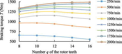
Braking torque versus number of rotor teeth at different rotational speeds.
When the ECR rotational speed is 500 r/min, the transient flux density at the inner air-gap before and after optimization is shown in Fig. 12. Due to the eddy-current in the stator, the air-gap flux density of one side facing to the rotor tooth is weakened, while that of the other side slightly increased. The air-gap flux density distribution changes with the variation of the size of rotor teeth. Moreover, before and after optimization, the average reduction of air-gap flux density is 0.181 T and 0.186 T respectively. It indicates that the eddy-current density and the braking torque are larger after optimization.
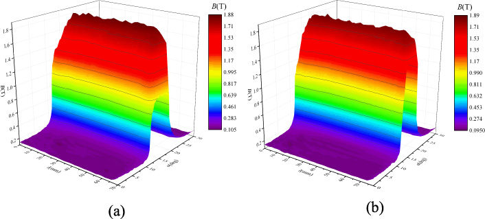
Transient magnetic flux density surface (a) before and (b) after optimization.
Figure 13 shows the comparison of braking torque before and after optimization at different rotational speeds. After optimization, the braking torque increases obviously, and the average optimum rate is 15.1%.
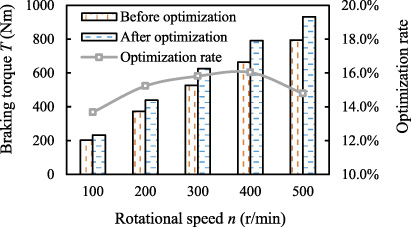
Braking torque versus rotational speed before and after optimization.
Layout of the test bench
The dual air-gaps and liquid-cooled ECR prototype was manufactured, and the bench tests were carried out to study the performance of the ECR and validate the FEM calculation. Figure 14 is the layout of the test bench. To meet the test requirements for different test modules, the test bench is mainly composed of electric control system, driving system and measuring system. It includes the motor, the ECR, the data acquisition system, the cooling system, the torque-speed sensor, the current sensor and the temperature sensor. Figure 15 shows the prototypes of traditional ECR and dual air-gaps and liquid-cooled ECR. The temperature sensor is used to measure the outlet coolant temperature. The motor drives the ECR rotor. The torque-speed sensor measures the braking torque and rotor rotational speed and transmits them to the data acquisition system. The cooling system is used to maintain a lower working temperature of the dual air-gaps and liquid-cooled ECR.
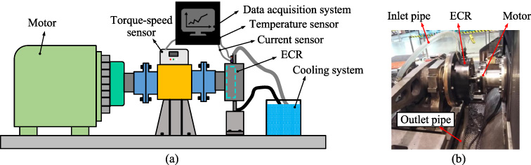
Layout of the test bench. (a) Schematic diagram. (b) Experimental setup.
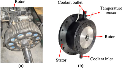
ECR prototypes. (a) Traditional ECR prototype. (b) Dual air-gaps and liquid-cooled ECR prototype.
Figure 16 shows the comparison between braking torque obtained by measurement and calculation at different speeds (the excitation current is 110 A). The test results show that the measured value is in good agreement with the calculated value at low speed, and the error is 5.5% when the speed is 500 r/min. The model simplification and the measurement may cause the error. The accuracy of the simulation model can meet the engineering requirements. With the increase in speed, the braking torque is decreased as a significant amount of heat energy makes the stator temperature rise rapidly and changes the electromagnetic properties of the stator material. However, the effect of temperature is not considered in the simulation model. The error also increases, and it is 14.1% when the speed is 1000 r/min.
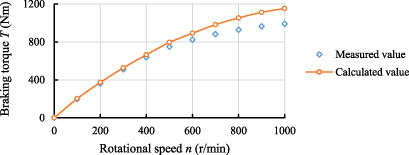
Comparison of braking torque obtained by measurement and simulation at different speeds.
Figure 17 shows the variation of braking torque with speed at different excitation currents. When the speed reaches 1000 r/min, the braking torque no longer increases. When the speed beyond 1000 r/min, the braking torque will decrease, even if the excitation current is high. The braking torque can be equally divided to four levels by controlling the excitation current, and the current increment of the high level is more significant than that of the low level. The braking power is approximately proportional to the speed.
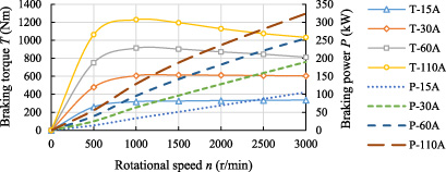
Braking torque and braking power versus rotational speed at different excitation currents.
The continuous braking characteristics of 6 minutes for two types of ECRs were tested. The variation of braking torque and temperature with time is shown in Fig. 18. The test results show that the initial braking torques of the two ECRs are almost the same, about 1370 Nm. However, the temperature of the traditional ECR reached more than 400 °C at the 6th minute with the increase of time, and the braking torque decreased to 620 Nm. The heat fade (the ratio of braking torque reduction to initial value in 6 minutes) was 54%. The dual air-gaps ECR reached a temperature balance at the 3rd minute, and the outlet coolant temperature rose by 28 °C. Additionally, the braking torque decreased to 1200 Nm, and the heat fade was only 13%. Therefore, the dual air-gaps and liquid-cooled ECR has better continuous braking performance than the traditional ECR.
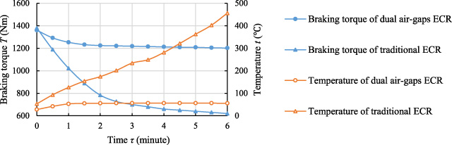
Variation of braking torque and temperature with time.
As auxiliary braking device, ECRs should give fast braking force to ensure safety, which requires good response characteristics. As mentioned in Section 2, the dual air-gaps ECR has an integrated coil, whose inductance is significant when the voltage is applied. Compared with the traditional ECR, the braking torque response time of dual air-gaps ECR is slightly longer. The coil current is made of the steady and transient components:
Figure 19 illustrates the response time comparison of exciting current and braking torque between the two ECRs. When the coil voltage is constant 48 V, the response time of excitation current of the traditional ECR is shorter. The reason is that the inductance of the individual coil of the traditional ECR is 0.3 mH, while that of the integrated coil of dual air-gaps ECR is 22 mH. The braking torque of dual air-gaps ECR is stable after the 0.6th second. However, the transient process of braking torque of the traditional ECR only needs 0.04 seconds.
To shorten the response time of dual air-gaps ECR, the transient process can be accelerated by increasing the initial applied voltage. As shown in Fig. 19, the applied voltage is 72 V from 0 to 0.3rd second, and then drops to 48 V by voltage controller after 0.3 rd second. It can be demonstrated that the braking torque has reached a steady state after 0.4 th second, and 33% of the response time is shortened compared with the constant applied voltage of 48 V.
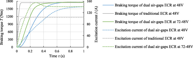
Response time comparison of exciting current and braking torque between the dual air-gaps ECR and traditional ECR.
This paper presents a novel dual air-gaps and liquid-cooled ECR with an integrated excitation coil, which has many advantages such as fast response, light rotor weight, and low working temperature. Based on combining 3-D FEM and Kriging approximation model, the rotor tooth structural parameters are optimized, and the number of rotor teeth is determined to be 12. After optimization, the braking torque increases by 15% and the weight of the rotor tooth decreases by 9.5%. The optimal results indicate the effectiveness of this optimization method. The bench test results show that the calculated braking torque agreed reasonably well with the measured results. The transient braking torques of the traditional and new ECRs are almost equal, but the new ECR has better continuous braking performance. The heat fade ratio of the new ECR is only 13% in 6 minutes, which is much lower than 54% of the traditional ECR. The response time of new ECR is slightly longer, but it can be shortened by increasing the initial excitation voltage. The dual air-gaps and liquid-cooled ECR may be applicable to heavy vehicle auxiliary braking.
Footnotes
Acknowledgements
This work was supported in part by the National Natural Science Foundation of China under Project 51741701 and 51777003, and Natural Science Foundation of Beijing Municipality under Project 3182007.