
Abstract
This paper studies the impact of Poloidal Field (PF) coil current disturbance on plasma shape in Experimental Advanced Superconductive Tokamak (EAST). First, the concept of the free-boundary equilibrium problem is studied. Based on the non-rigid plasma model, a free-boundary equilibrium solver developed in MATLAB software is presented to calculate the flux distribution and plasma profile of EAST plasma equilibrium, and the results are validated against the experiments. Second, given a typical double-null plasma equilibrium, the responses of plasma shape to the lower PF coil currents are computed using the orthogonal test method. The dependences of the elongation and triangularity of plasma shape on PF coil currents are obtained, showing that the currents in PF6 and PF8 have the greatest impact on triangularity and elongation for lower single-null (LSN) divertor configuration, respectively. And for double-null (DN) divertor plasma configuration, PF5 and PF7 play equally important roles due to the up-down symmetry. The conclusions will be useful for the design of EAST plasma shape feedback control.
Keywords
Introduction
A tokamak reactor is one of the most promising approaches to implementing nuclear fusion [1]. EAST is a D-shaped cross-section tokamak with 12 independent full superconductive PF coils that are symmetrically located outside the reactor vessel [2], as shown in Fig. 1. The plasma is feedback controlled by adjusting the currents in PF coils [3]. Since the PF coils are highly coupled and each is used to provide the magnetic field necessary to maintain and shape the plasma, it is essential to decide the contribution of each PF coil to the control of plasma parameters [4]. Given this problem, in the ongoing design of an optional plasma-shape feedback controller, it is necessary to calculate the responses of the plasma shape parameters (namely, elongation, triangularity, squareness and X-point position) to each PF coils, which can be obtained by solving the free boundary equilibrium problem [5]. More specifically, based on a given plasma equilibrium, recalculating the plasma equilibrium after an artificial disturbance is added to the PF coil current.
The present plasma control system of EAST tokamak is carefully introduced in [6]. As a matter of fact, the decoupling of the plasma shape controller from the vertical stabilization has been achieved by a frequency separation approach [2]. And to decouple the control for plasma parameters, the optimized control vectors are used to distribute on the PF circuits the contribution of each control loop [7]. In order to achieve a high performance of plasma decoupled control for tokamak, many researches have been conducted on response of plasma to PF coils. R. Albanese et al. studied the dynamic responses of plasma boundary and flux expansion to PF coil currents in EAST tokamak [7]. Furthermore, they proposed an integrated control scheme to control both plasma boundary and flux expansion. S.L. Chen et al. compared the different linearized plasma response models while studying the electromagnetic interaction between the plasma and surrounding conductors [8], and the CarMa0 code was used to simulate the tokamak discharges. Q.L. QIU et al. employed the Tokamak Simulation Code (TSC) to compute the responses of vertical position and radial position to the PF coil currents [9]. However, the calculation was complex and took a long time. In this paper, calculation of responses of plasma shape to the PF coil current disturbance is presented by solving free-boundary equilibrium problem. First, A free boundary equilibrium solver based on GAQ plasma model (B.B. Brown, 1977) is developed to calculate the plasma shape and flux distribution in the vacuum vessel by solving the GradShafranov equation [10], the calculation result of EAST shoot 73625 is compared to the experiment to verify the solver. Afterwards, the orthogonal test method is used to choose the combination of PF current disturbances applied in the tests.
East plasma equilibrium calculation
Free boundary equilibrium calculation for EAST
The quasi-static plasma equilibrium is described by the Grad–Shafranov (GS) equation derived from the steady state ideal Magneto-hydrodynamic(MHD) equations, and is given by
The GS equation is a nonlinear second order partial differential equation, in order to solve it, a free-boundary equilibrium solver is developed in MATLAB software (MathWorks, USA) based on the non-rigid plasma model. The solver has the same kernel algorithm as in the EFIT code. It uses the reconstructed equilibrium of EFIT as input, and for free boundary equilibrium calculation, it can change the initial values of PF coil currents directly in the MATLAB command window, which compared to EFIT is more convenient and user-friendly. The solver divides the computational domain into a 64 × 64 grid to calculate the flux distribution. The plasma is divided into several current filaments and the GS equation is linearized according to the GAQ current profile assumption, which is described as
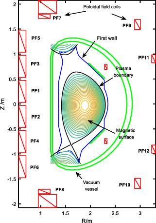
Cross-section of EAST and plasma.
The adjustment of PF coil currents will cause a flux disturbance in the entire region: Step-1: Initialize the plasma equilibrium before PF coil current disturbances are added. We load from gfile the data of plasma boundary, magnetic flux distribution, P’ profile (pprime_0) and FF’ profile (ffprime_0). Then calculating the normalized flux distribution. Next, initializing the coefficients of GAQ current model: Step-2: Adjust the PF coil currents. Step-3: Calculate the plasma current profile: Firstly, calculating the displacement of the center of plasma (δrδz) and variation of normalized flux between two iterations according to (3). Secondly, calculating the distribution of plasma current using (4)-(7). After that, coefficient 𝜆 is recalculated to keep the total plasma current constant, also the center of the plasma current is recalculated, and the P’ and FF’ profiles are updated by (8). Step-4: Calculate the flux produced by PF coil currents and plasma current. Step-5: Find out the plasma boundary and magnetic axis, calculating the normalized flux. Step-6: Compute the flux variations on the grids and judge the convergence of equilibrium calculation by checking the equation: Step-7: Calculate the equilibrium parameters and output the result.
To verify the developed free boundary equilibrium solver, the simulation of EAST pulse 73625 at 1.8 s was carried out, and the result was compared to the experiment (EFIT reconstruction). In particular, starting from the reconstructed plasma equilibrium at 1.2 s by off-line EFIT code, the plasma equilibrium at 1.8 s was predicted with the PF coil currents and total plasma current set as target values, while the PF currents were inputs. A comparison of the key plasma parameters is shown in Table 1 and the plasma shape comparison is shown in Fig. 3. It can be seen that the key parameters of plasma profile calculated by simulation are almost consistent with the experiment, and the biggest error of plasma shape in simulation is 0.4 cm as compared with the experiment, which proves the precision as well as reliability of the simulation tool.
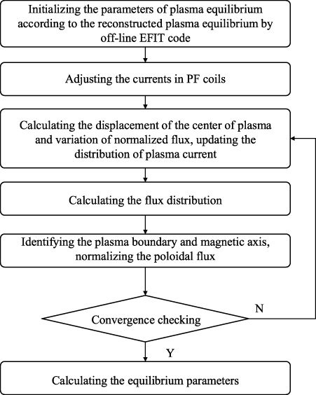
Flow chart of the free boundary equilibrium calculation.
Comparison of equilibrium parameters
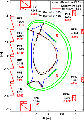
Comparison of plasma shape between the simulation and experiment. The calculated plasma boundary (red line) is superimposed on the EFIT boundary (black dashed line) at 1.8 s. The black dotted line represents the plasma boundary at 1.2 s.
EAST plasma control system (PCS) controls the plasma shape by controlling the applied magnetic field generated by PF coil currents. Currently, there are two control algorithms: “RZIP” control, which controls the plasma radial position (R), vertical position (Z) and current (Ip); and “isoflux” control, which controls the magnetic flux at a set of control points. Both two control algorithms adopt the proportional-integral-derivative (PID) controller, and for each controlled variable, optimized control vectors (M_matrix column in EAST PCS) which links the variations of the plasma parameters to the variations of PF coil currents is used to determine the contribution of 12 PF coil currents to the variation control. For other controlled shape variables (elongation and triangularity in this paper), it is possible to develop an integrated control algorithm that simultaneously controls multiple parameters. The M_matrix mentioned above can be decided through calculating the responses of shape parameters to PF coil currents exploiting the simulation tool presented in Section 2.
Taking shot 61782 for example, it is a typical double-null discharge with elongation 1.8, and plasma current up to 400 kA. The plasma equilibrium at 5 s is set as the initial condition. Since the PF coils are symmetrically powered, only the lower coils (PF2, PF4, PF6, PF8, and PF12) are studied. Recalculation of plasma equilibrium is conducted to obtain the plasma response after current disturbances are added to PF2, PF4, PF6, PF8, and PF12. To be specific, each of the PF coil currents is supposed to set to
The orthogonal test method is an efficient way to study pair-wise interactions [11]. It reduces the number of tests by choosing representative variable combinations based on the combinatorial theory. With this method, the parameters that affect the output are defined as “factors”, and the different values of factors are called “levels”. According to the numbers of the factors and levels, the orthogonal array L m (p q ) can be constructed. Here, L denotes the orthogonal test method, m is total number of simulations, p and q are numbers of levels and factors, respectively.
To calculate the plasma response, the shape parameters elongation 𝜅 and triangularity δ are set as target functions, the six PF coil currents are considered factors, five levels are selected corresponding to the current values. If we test all the possible combinations of these PF coil currents, a set of 56 = 15625 simulation cases is needed. But instead of testing all the combination of parameters, a L
25(56) orthogonal table as demonstrated in Table 2 is constructed to maximize the test coverage while minimizing the number of test cases to 25. To analyze the relationship between target functions and factors, the average value of each level for six factors and the range of each factor are computed by:
The results of 25 simulations are shown in Table 2. According to (11) and (12), the average value of each level and the range of each factor are calculated, Table 2 only shows the case that the target function is elongation for brevity, the full results are shown in Fig. 4. It can be concluded that the plasma elongation decreases monotonically with the increment of the currents in PF2 and PF4 and increases monotonically with the currents in PF6, PF8, PF10 and PF12. The plasma triangularity increases with the increment of the currents in PF2, PF4, PF6 and PF8 and decreases monotonically with the currents in PF10 and PF12. By comparing the range of each factor, R 4 and R 3 have the largest value when the target functions are elongation and triangularity, respectively, which indicates that among all the PF coil currents, the disturbances in PF6 and PF8 influence the triangularity and elongation dramatically. Generally speaking, the main role of a PF coil in plasma control is decided by its position and turn number, it is easy to qualitatively analyze the influence of a PF coil on the plasma, while the quantitative assessment can be carried out by linear fitting the experiment data. According to the simulation results, the response matrix that describes the linear relationships between elongation, triangularity and PF coil currents is calculated, the elements are values of PF coil currents (unit: A) per unit of elongation or triangularity, as shown in Table 3.
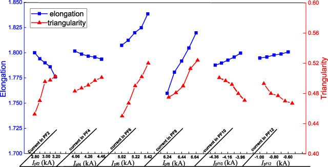
The dependence of elongation and triangularity on PF coil currents.
Orthogonal Array with 6 Factors and 5 levels
Response matrix of elongation and triangularity to PF coil currents
To study the impact of PF current disturbance on tokamak plasma shape, a free boundary equilibrium solver is presented in this paper, it is an efficient and effective simulation tool, and to reduce the number of simulations, the orthogonal method is used to design the tests. The response curves of elongation and triangularity in relation to the PF coil currents are obtained, as for other plasma parameters, the proposed methodology can also be applied to calculate their responses to PF coil currents. In the future work, the presented calculation will be used to design the feedback gain matrix in the EAST shape controller.
Footnotes
Acknowledgements
The author is grateful to Z.P. Luo for the support to the simulation. This work is supported in part by the National Natural Science Funds of China under Grant 51677051 and in part by Institute of Plasma Physics Chinese Academy of Sciences.