
Abstract
Electromagnetic linear actuator (EMLA) is an alternative of the conventional damper in vehicle suspensions and harvests suspensions vibration energy which is wasted generally. Due to large variations of its Back Electromotive Force (Back-EMF), it will thus be interest to investigate how to recycle the electricity efficiently. In this paper, to improve the recycling efficiency of the EMLA, a feedback energy circuit featured with combination of parallel switchover supercapacitors technology and a boost-buck DC-DC converter is proposed on the basis of the generating characteristics of a newly designed EMLA. By modeling the feedback energy circuit, its dynamic characteristics are simulated and its efficiency is investigated. The results of simulations and experiments show that the feedback energy circuit can achieve a wide range of energy recovery regardless of large variations of Back-EMF induced by the EMLA. Simultaneously, by keeping the boost-buck ratio less than 3, the efficiency of energy recovery is high, in some cases could reach 94%.
Introduction
Energy harvesting is an increasing promising technology that can convert mechanical energy, usually vibration, into electricity that is used to power other devices [1]. The example of this application is harvesting of vehicle suspensions vibration energy. Under the road input, the traditional passive suspensions absorb road vibration by the dampers and convert kinetic energy into heat. The harvesting of the suspensions vibration energy in dampers can improve energy efficiency of vehicles. Mucka [2] quantitatively calculated dissipated power in a damper of automobile suspension and found that road surface type, velocity and road roughness are all important factors of suspensions energy harvest power. Wang et al. [3] calculated the energy consumptions of a damper at different vehicle speeds and road conditions. The results demonstrated that on the road level C and driving speed of 60 km/h, the RMS of regenerative power is about 100 W. Zuo et al. [4] found that at 60 mph on good and average roads, 100–400 W average power is available in the suspensions of a middle-sized vehicle. Therefore, active suspensions which can harvest the suspensions vibration energy are proposed. Originally, the active suspensions and semi-active were proposed to improve the dynamic characteristics, such as body roll and pitch control, handing and stability of vehicles, ride comfort [5,6]. However, the actuators which are the key parts in the active suspensions will consume large amounts of energy for the improvement of dynamic characteristics [7]. So, regenerative active suspensions are proposed to harvest suspensions vibration energy while maintaining good dynamic characteristics. There have been substantial interests in use of three types of actuators employed in regenerative active suspensions, i.e., hydraulic actuators, mechanical actuators, and electromagnetic linear actuator (EMLA). Hydraulic regenerative type actuators can harvest suspension vibration energy into electricity by employing a hydraulic motor paralleled with a generator [8]. Mechanical actuators, such as rack-and-gears and ball screws, can convert rotary motion to linear motion and drive AC/DC motors to recycling suspension vibration energy simultaneously [9,10]. Unlike hydraulic and mechanical actuators, EMLA can directly convert kinetic energy of suspensions oscillation into electricity in the absence of intermediate conversion links, which is called electromagnetic active suspensions featured with direct-drive [11–13]. Additionally, with appropriate control strategies the potential to realize energy harvest can be enhanced. Zhang [14] founded that a maximum of 10% fuel efficiency can be achieved with a regenerative shock absorber. Sagiv et al. [15] presented a simple and energetically efficient controller which enables an accurate force-velocity suspension characteristic control as well as energy regeneration control. Simultaneously, the developments of supercapacitors in EV and HEV offer good opportunities for the applications of electromagnetic active suspensions [16], because the supercapacitors can store and release energy rapidly according to the demands of the EMLA.
As discussed above, although the EMLA and the supercapacitors promote the applications of electromagnetic active suspensions, the variations of frequency and amplitude of EMLA’s Back Electromotive Force (Back-EMF) is large due to road irregularities, which cause the difficulties in storing energy [17]. Therefore, how to efficiently recycle electricity is a vital problem. Recently, there have been substantial interests in the researches about energy recovery from electromagnetic active suspensions. Sabzehgar et al. [18] designed a feedback energy system for the electromagnetic active suspensions, which includes a linear DC machine, a power electronic circuity, and a battery. To improve the recycling efficiency, a bridgeless boost converter is utilized to control power switches of lower bridge arm to adjust boost amplitude. Guo et al. [19] investigated a feedback energy equipment for an electromagnetic active suspension featured with integration of ball screw and permanent motor. Its feedback energy circuit consists of three-phase full-bridge rectifier, DC/DC converter, data acquisition, storage system, rechargeable battery, and loads. Although they had some achievements in improving recycling efficiency, it is difficult to harvest the feedback electricity when Back-EMF of the EMLA is lower than rated voltage of supercapacitors or batteries. This phenomenon is called dead band [20]. To avoid the dead band, Wang et al. [21,22] proposed a bidirectional voltage charging circuit with a boost chopper module, which is featured with an inductance and a high frequency switch. Even when the Back-EMF produced by the EMLA is lower, the electricity still can be recovered effectively due to the energy storage function of inductance. By adding a boost module located after a full bridge rectifier, Chen et al. [23] also achieves the goal in spite of the dead band.
Therefore, design a reasonable boost convertor is an effective way to avoid dead band. However, the boost convertors presented above were just focused on boosting the lower Back-EMF while not limiting the boost ratio. The boost ratio has its optimal limit to achieve high efficiency, usually less than 3. Due to large variations of the Back-EMF of the EMLA, the boost or buck ratio probably exceeds 3, which consequently compromises efficiency of the converters. To keep the boost-buck ratio less than 3, in this paper, a high-efficiency feedback energy circuit is proposed for the electromagnetic active suspensions with a newly designed EMLA. Particularly, parallel switchover supercapacitors technology is employed to divide Back-EMF into several ranges, then a cascaded boost-buck DC-DC converter is utilized to convert each range into fixed voltage which is one of the two paralleled supercapacitors voltages. Specifically, when the Back-EMF is in a low level, the rectified Back-EMF will be boosted or bucked to the lower supercapacitor voltage. In case of the high level Back-EMF, the rectified Back-EMF will be boosted or bucked to the higher supercapacitor voltage. In this way, the boost-buck ratio can be limited within 3. Furthermore, the supercapacitors utilization factor will become high.
The remainder of this paper is organized as follows. An EMLA used in electromagnetic active suspensions is proposed firstly. According to the generating characteristics of the EMLA under different vibration conditions, the feedback energy circuit and its configuration are presented. Then, mathematic model of the circuit is derived and specific parameters are given. Finally, by simulations and comparing the results of simulations to experiments, the feasibility of the feedback energy circuits is validated, which means that the feedback energy circuits can achieve high efficiency.
Electromagnetic linear actuator
The proposed EMLA is a replacement of the conventional damper and the parameters of the suspension are shown in Table 1. Under different road conditions and different speed, the maximum damping force of the original damper and the corresponding speed are 800 N and 0.19 m/s, respectively. To achieve above performances the newly designed EMLA is proposed, its specific parameters and structure are shown in Table 2 and Fig. 1, respectively.
Parameters of the suspension
Parameters of the suspension
EMLA ’s performance parameters
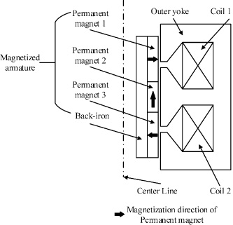
Structure of the EMLA.
The proposed single-phase, moving-magnet tubular EMLA mainly comprises magnetized armature, outer yoke and coils. The back-iron and outer yokes both are made of DT4C, which has high magnetic permeability and small reluctance. The materials for the permanent magnets are NdFe45SH. The 2-pole magnetized Halbach armature employs 3 ring magnets, two being radially magnetized and one being axially magnetized. The axially magnetized magnet provides a return path for the radial flux, therefore the flux density remaining on the inner bore of the magnets is relative small. As a result, the Halbach magnets can be mounted on the thin tubular back-iron, which may reduce mass of the mover. Compared with a type of motor topology which has a stationary back-iron [24], this structure just has one air-gap between the mover and the stator, thus the eddy current loss can be reduced due to small change of magnetic field caused by the mover’s reciprocating motion. This unique feature is beneficial to the EMLA to be used in high frequency vibration situations, such as vehicle suspensions. The two coils are connected in anti-series, thus phenomena of magnetic field leakage can be improved. Such a structure not only results in high thrust force capability, but also improves efficiency.
When the EMLA is applied to electromagnetic active suspensions, there are two operating modes, one is motor mode, and the other is generator mode. When the two coils are excited, an alternating magnetic field will be produced in the air gap. In motor mode, by the interaction between the constant magnetic field generated by the permanent magnets and the alternating magnetic field, the thrust force will be generated to improve dynamic characteristics of suspensions. In generator mode, the armature moves with wheel of vehicles and the coils flux linkage is modulated by the linear movement of the armature, thus the Back-EMF is induced. Through a proper feedback energy circuit, the harvested vibration energy can be used to drive loads or charge batteries.
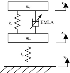
Before design of the feedback energy circuit, it is very significant to obtain the generating characteristics of the EMLA under different motion excitations. The ranges of the Back-EMF and the output power are important references for the design of the feedback energy circuit. Some design parameters, such as current range, power devices selections, especially the paralleled supercapacitors voltages, are all based on the Back-EMF and the output power. Thus, this paper is mainly focused on the maximum Back-EMF and output power of the EMLA under different frequencies within the stroke. A dynamic model of 1/4 electromagnetic active suspension shown in Fig. 2, which is governed by coupled electromagnetic and mechanical subsystems [25], is established. The EMLA can be given in electromagnetic field, then the model of EMLA is imported into the mass-spring-damper subsystem. The relationship between the two subsystems are expressed in Fig. 3. To simulate the road excitation, displacement input with different frequencies (rigid body motion frequency with value from 1 Hz to 15 Hz) and amplitudes, namely x r , is exerted on the 1/4 electromagnetic active suspension.
Quarter electromagnetic active suspension model.
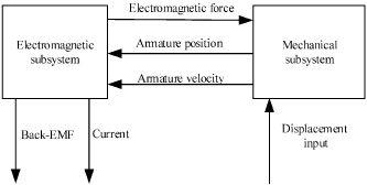
Coupling relationship between EMLA and mechanical subsystem.
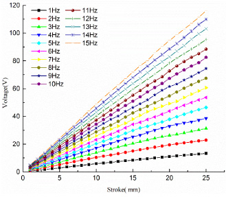
As shown in Fig. 4 and Fig. 5, the output voltage, namely the Back-EMF, is proportional to speed of the armature and the Back-EMF coefficient is k
v
. Therefore, under certain frequency, with the increase of stroke, the armature speed increases linearly, and the output voltage increases linearly also. Likewise, under certain stroke, the output voltage increases linearly with frequency due to increasing speed of the armature. Consequently, the current of the coils will increase. The relationship between output voltage and current is given as,
Output voltage of the EMLA.
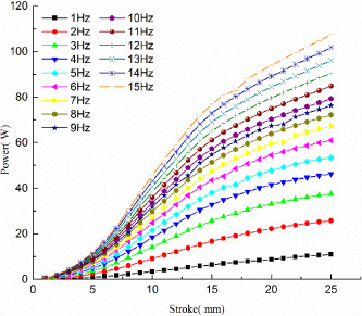
Output power of the EMLA.
Because of the nonlinear relationship between the Back-EMF and the current, with the increase of stroke, the “saturation” phenomena of the output power characteristic is observed as shown in Fig. 5. The maximum output voltage and output power are about 116 V and 110 W, respectively [26].
Configuration
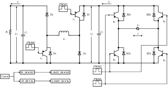
In the electromagnetic active suspensions, since the armature of the EMLA moves with the displacement input of road, the high-frequency and bi-direction electricity induced from the EMLA can’t be utilized directly to charge the batteries. Additionally, from above analysis about the generating characteristics of the EMLA, the variations of the Back-EMF and the output power are very large, which causes difficulties in efficiently harvesting electricity. To solve these problems, a newly designed feedback energy circuit, which includes a modified single-phase H-bridge AC-DC converter, a cascaded boost-buck DC-DC converter, and an energy storage device including a battery and two supercapacitors, is proposed as shown in Fig. 6. The features of the feedback energy circuit can be drawn as follows.
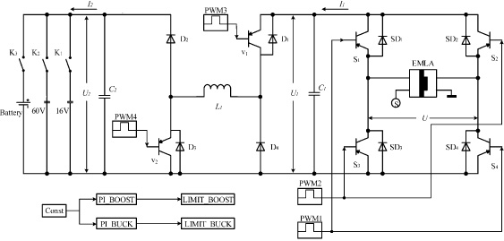
Configuration of the feedback energy circuit.
Firstly, the Back-EMF of the EMLA, namely U, is transformed into uni-direction direct current by a rectifier. This single-phase H-bridge AC-DC converter can achieve power decoupling as well as maintain basic function of a conventional PWM rectifier without additional power device. The voltage of filter capacitor C 1, which is the output voltage after the H-bridge in generator mode and also the supply voltage before the H-bridge in motor mode, is called DC bus voltage, namely U 1. U 1 can be controlled by adjusting PWM1 of S1 and S4 or PWM2 of S2 and S3.
Secondly, due to large variations of the DC bus voltage and the dead band, the boost-buck DC-DC converter and two paralleled supercapacitors with voltage of 16 V and 60 V are employed to improve efficiency. When U 1 is smaller than 30 V, by adjusting the duty ratio of PWM3 or PWM4, U 1 can be boosted or bucked to the lower supercapacitors voltage of 16 V. Similarly, when U 1 is larger than 30 V, U 1 will be boosted or bucked to the higher supercapacitors voltage of 60 V. By this way, the boost-buck ratio can be maintained less than 3. PI control method is applied to adjust the duty ratio of PWM3 or PWM4. Additionally, the supercapacitors utilization factor is high.
Finally, in the energy storage device, a battery also is paralleled with two supercapacitors. The paralleled battery and two supercapacitors provides a flexible way to recycle the energy after the boost-buck DC-DC converter, which means that according to the boost-buck voltage the two supercapacitors can be charged respectively and then the supercapacitors are used for charging of the battery.
Parallel switchover supercapacitors
As discussed above, the maximum output voltage of EMLA is 116 V and the boost-buck ratio of DC-DC converter must be less than 3, so only one supercapacitor used in storage device is not enough. Therefore, parallel switchover supercapacitors with rated voltage of 16 V and 60 V respectively are used. The target voltage U 2 can be controlled to attain the rated voltage of one of the two supercapacitors by adjusting the boost-buck ratio of DC-DC converter with appropriate control strategy.
The supercapacitor capacity C is given as:
Base on the output power of the EMLA as shown in Fig. 5, the maximum and minimum P are set to 5 W and 110 W respectively. Assuming that the t c is 600 s, the calculated C of the two supercapacitors are 23 F and 37 F, respectively, for safety allowance, the design value are 32 F (U cmax is 16 V) and 45 F (U cmax is 60 V).
As shown in Fig. 7 the H-bridge AC-DC converter consists of four insulated gate bipolar transistors (IGBTs) with anti-parallel diodes, the AC Back-EMF induced by the EMLA, namely U, is converted into direct current across S1 and S4 or S2 and S3 depending on the direction of the Back-EMF.
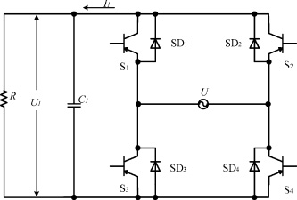
Schematic of H-bridge AC-DC converter.
When the R is infinite, the relationship between output voltage and input voltage is given as,
When the R is little, the relationship between output voltage and input voltage is given as,
Equations ((3))–((4)) show the DC bus voltage and Back-EMF of the EMLA is very close, which proves that the H-bridge AC-DC converter could meet the functional requirement without changing voltage significantly. However, due to the presence of the filter capacitor C 1, the U 1 will become larger when the U is very small. This situation is beneficial to improve the efficiency in low voltage case.
In the cascaded boost-buck DC-DC converter shown in Fig. 8, switch V 1 and V 2 are used to choose boost mode or buck mode by PWM from controller. L 1 is an inductance, C 1 and C 2 are filter capacitors, U 2 is target voltage, I 1 is the DC bus current, and I 2 is output current.
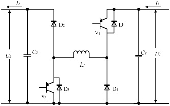
Schematic of Boost-Buck chopper.
In boost mode the switch V
1 is open and the switch V
2 is controlled with PWM, so the relationships between output and input are given as,
When the switch V
2 is closed and the switch V
1 is controlled with PWM, the chopper is in buck mode and the relationships between output and input are given as,
To calculate the filter capacitors and inductance, U 2 and I 2 should be determined firstly. Because two supercapacitors with voltage of 16 V and 60 V are selected, so U 2 is set as 16 V when U 1 is from 0 V to 30 V. If U 1 is larger than 30 V, U 2 is set as 60 V. Consequently the output current can be achieved from Eqs ((4))–((7)), and the results are listed in Table 3.
Design parameters of cascaded boost-buck DC-DC converter
The value of the inductance and capacitors are given as,
The calculated value of inductance and capacitors are 269 μH and 50 μF, respectively, for safety allowance, L 1, C 1, andC 2 are selected as 470 μH, 220 μF, and 220 μF, respectively.
The above designed feedback energy circuit is modeled as shown in Fig. 9. The energy storage device is replaced by a power resistor R 1 with value of 500 W and 10 Ω, and the EMLA is replaced by an AC power source. This simulation model can be easily realized in experiments and also the simulation results will be conveniently compared with test results.
Schematic diagram of the simulation model.
As shown in Fig. 3, the maximum Back-EMF is 116 V at frequency of 15 Hz, so the sinusoidal alternating voltage U is set to the same value as the maximum Back-EMF. In Fig. 10, after rectification the sinusoidal alternating voltage U is converted to pulsating DC bus voltage with minimum of about 10 V.
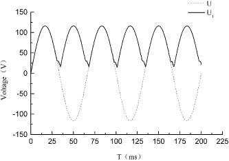
Simulated rectification characteristics of the H-bridge AC-DC converter.
After the H-bridge AC-DC converter, the DC bus voltage is fed into the cascaded boost-buck DC-DC converter. As discussed in Section 4.2.2, the DC bus voltage will be boosted or bucked to the target voltage according its voltage amplitude. To achieve this goal better, the PI control method is adopted and the value of K p and K i are 0.00875 and 0.001 respectively. The simulation results are shown in Fig. 11, although the target voltage U 2, namely the terminal voltage of the power resistor, has some fluctuations, its value almost reaches idea value. Therefore, the value of designed inductance and capacitors can meet the requirements that the cascaded boost-buck DC-DC converter should achieve.
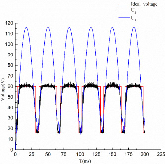
Simulated boost-buck characteristics of the cascaded DC-DC converter.
To evaluate efficiency of the feedback energy circuit, the curve of the target voltage (U
2) is also investigated and the results are shown in Fig. 11, the curve of output current (I
2) is depicted in Fig. 12. And according to the following equation,
When the effective value of input voltage (U) is different, such as 10 V, 25 V, 45 V, 80 V, the corresponding effective value of input currents (I) are approximately 3.10 A, 6.67 A, 6.00 A, 4.26 A. In this case, the efficiency is 82.6%, 85.3%, 90%, 94.1%, respectively.
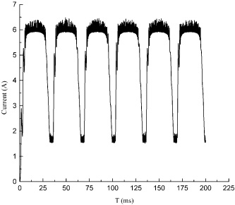
The curve of output current I 2.
To validate the simulation model the feedback energy circuit prototype and its platform are fabricated as shown in Fig. 13. The only difference between the simulation model and the prototype is that the AC power source is replaced by the DC power source, because the 15 Hz AC power source is difficult to achieve. Therefore, by adjusting the value of input voltage U continuously the dynamic characteristics of target voltage U 2 and current I 2 can be observed. When the value of U is 10 V, 25 V, 45 V and 80 V, respectively, the results of experiments are shown in Fig. 14 and Fig. 15. Similar to the simulated results, the U 2 also reaches its idea value.
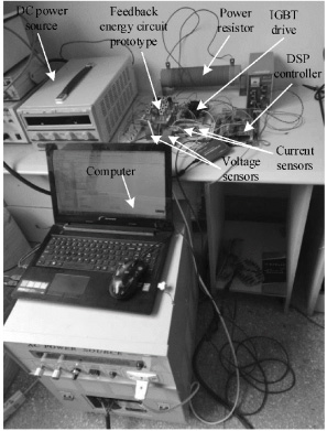
The physical map of prototype and platform.
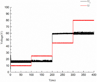
Voltage results of experiments.
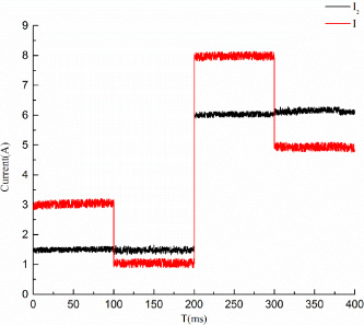
Current results of experiments.
The efficiency of energy transmission can be calculated approximately on the basis of the tested results as listed in Table 4. The averaged value of the efficiency is about 90%, which is higher than the maximum efficiency of 82.3% in [23].
Tested efficiency of feedback energy circuit
The power switch components, such as IGBT, diode, are the key of dissipating energy, which will influence the efficiency. As long as the current goes through this switches, the energy will be dissipated. So choose switching device of low energy consumption is very important for reducing the energy loss. In addition, the inductance and capacitors also cause energy loss. These factors are inevitable in the feedback energy circuit, so the 𝜂 calculated as 90% can meet the system requirements.
In this paper, aiming to efficiently recycle electricity produced by the EMLA, the feedback energy circuit for the electromagnetic active suspensions is proposed and its main features can be drawn as follows.
The feedback energy circuit can achieve a wide range of energy recovery regardless of large variations of Back-EMF induced by the EMLA. The combination of parallel switchover supercapacitors technology and a boost-buck DC-DC converter enable the feedback energy circuit to limit the boost-buck ratio within3, so the efficiency of energy recovery is high, in some cases could reach 94%.
Footnotes
Acknowledgements
This work was supported by the [Natural Science Foundation of Jiangsu Province] under Grant [number BK20130757]; the [Peak of the Six Talents of Jiangsu Province] under Grant [number 2015-JXQC-004].