
Abstract
In the paper, the Wind Driven Optimization WDO algorithm is applied to the optimal shape design of a class of switched reluctance motors. The goal of the optimization is to identify a class of geometries which maximize the torque and simultaneously minimize the iron losses of the motor. Because of the twofold design criterion, the multi-objective version of the wind driven algorithm M-WDO is used. Results are eventually compared with those obtained by means of a standard genetic algorithm GA. For construction of optimized model of switched reluctance (SR) motor measurements of resistance and inductances vs. rotor position of commercial motor made of steel and non-optimized model motor made of soft magnetic composite were measured. On the basis of changes in inductance, electromagnetic torques were calculated. Results of B
Keywords
Introduction
Over the last two decades, evolutionary algorithms (EAs) have proven to be successful in solving optimization problems in the area of computational electromagnetism. In fact, EAs do not require the objective function gradient to identify the search direction, and are global-optimum oriented. Moreover, they are able to find a solution when the optimization problem is characterized by several constraints or exhibits discontinuities. Often, EAs are inspired by the models of natural phenomena: for instance, the biogeography-based optimization algorithm [1], which is inspired by the geographical distribution of species in an ecosystem, has been applied in MEMS design [2, 3]. More recently, wind-driven optimization, inspired by the wind motion, which takes place in the high atmosphere to compensate the pressure imbalance, has been proposed and applied in antenna array design [4].
In research works a commercially available Switched Reluctance Motor Drive was used. This drive mainly was used in Maytag washing machines model “Neptune”. This motor was developed by Emerson Electric Co., whereas an electronic supply and control system developed by Switched Reluctance Drives Ltd. This type of electric drive exhibits high torque, high speed, soft starts, rapid reversal and tight control. This motor have low manufacturing cost but high cost of supply and control system. However overall cost is lower than cost of similar performance drives with an another motor.
One of the main aims of work is to design and manufacture a model of Switched Reluctance (SR) motor with high efficiency using Soft Magnetic Composite (SMC) as a material for a stator and a rotor magnetic core. This material is more and more applied in commercially available motors and is widely used in research works dealing with new constructions of electric motors and actuators [11, 12]. The commercial motor have magnetic circuit made of electrical steel.
One of the main parameters of a SR motor is its inductance. Owing to different motor reluctance with changing position of a rotor in relation to a stator, inductance is variable.
For inductance measurements two motors were used. First motor was the commercial one and second was a model motor. The model motor is a motor with magnetic circuit made of SMC and it is our initial design made in previous research [9].
In last part of an article results of B
Multiobjective wind-inspired algorithm
WDO is inspired by the atmospheric motion of air parcels. In fact, wind blows in a way to equalise imbalances in the air pressure; likewise, in optimization the design points are moved from high-gradient to low-gradient positions. Accordingly, a swarm of
where the left-hand side gives the velocity of the ith out of p air parcels at time
The inertial term, depending on velocity at time The gravitational-like term gx, which biases the current position The pressure-gradient term (the main operator), where index i The Coriolis-like acceleration term, due to which the velocity of the
Positive-valued constants (
and the boundaries are checked to prevent any air parcel from exiting the design space. The procedure continues until the maximum number of iterations is reached.
In [5], it was proposed to generalise the algorithm, and make it able to solve a multi-objective optimization problem exhibiting
The motor is a 12/8 SRM [6, 9] made of Soft Magnetic Composite SMC material. Geometry and design variables are shown in Fig. 1.
Case study: geometry and design variables of the SRM.
Phase configuration consists of four series-connected coils per phase, driven by unipolar current with a constant value of 1 A. In the model, it is assumed that currents in the motor windings simulate 1-phase control mode (
Subregions of the magnetic circuit are characterized by different flux-density waveforms that are non-sinusoidal and exhibit different frequencies. Therefore, the loss curve of the SMC is considered at a frequency
A finite element model of the SRM has been implemented by means of a commercial software [7].
Geometric parameters ROR, RIR and BIT (Fig. 1) are selected as the design variables, subject to a set of constraints: overall diameter of the motor not exceeding 140 mm; Air-gap Length (AG) equal to 0.25 mm. Upper and lower bounds of design variables are reported in Table 1.
Range of design variables
Range of design variables
Iron losses for rotor (200 Hz) and stator (2 kHz).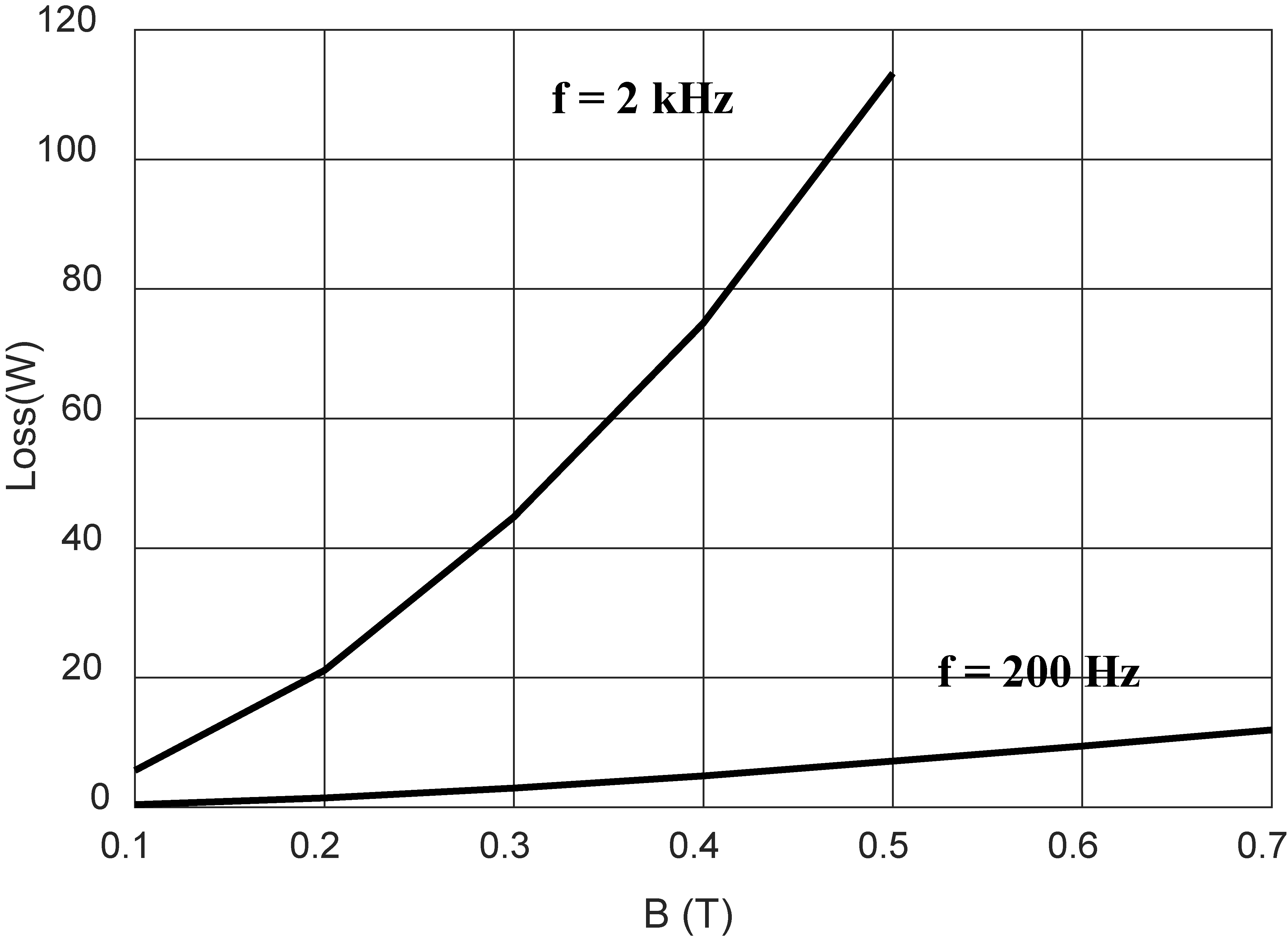
Constraints are handled by means of the exterior penalty method. In terms of the design vector
The following set of parameters tuning the M-WDO algorithm was considered: 20 parcels, 100 iterations, thermal coefficient RT
Inductance measurements of switched reluctance motors
Inductance can be measured with different methods e.g. such as using LCR meters or using ammeter and voltmeter. Measurements done by LCR meters can be made for different frequencies, but LCR meters can produce only a low value of a measuring current. For ironless inductors value of inductance is constant with changes of current. For magnetic circuits with ferromagnetic materials inductance is variable with changes of current in inductor’s wires.
For measurements of inductance of SR motor was used frequency generator, power amplifier, ammeter and voltmeter. By supplying a motor with sinusoidal voltage with defined frequency of 50 Hz, inductance is calculated from impedance and resistance of a motor’s phase. Measurement were carried for different values of current supplying a motor’s phase. For different values of current with the same angle of rotation, inductance has maximum 10% difference, because motor’s magnetic circuit is unsaturated. Inductance for each angle is an average value of inductances for different currents.
Phase resistances of SR motors were measured using ammeter and voltmeter for supplying each phase with DC current.
Rotation of motor’s rotor was conducted by a stepper motor with a resolution of 3
Parameters of switched reluctance motors
Parameters of switched reluctance motors
Optimization results: circle – M-WDO, star – GA, dot – random sampling.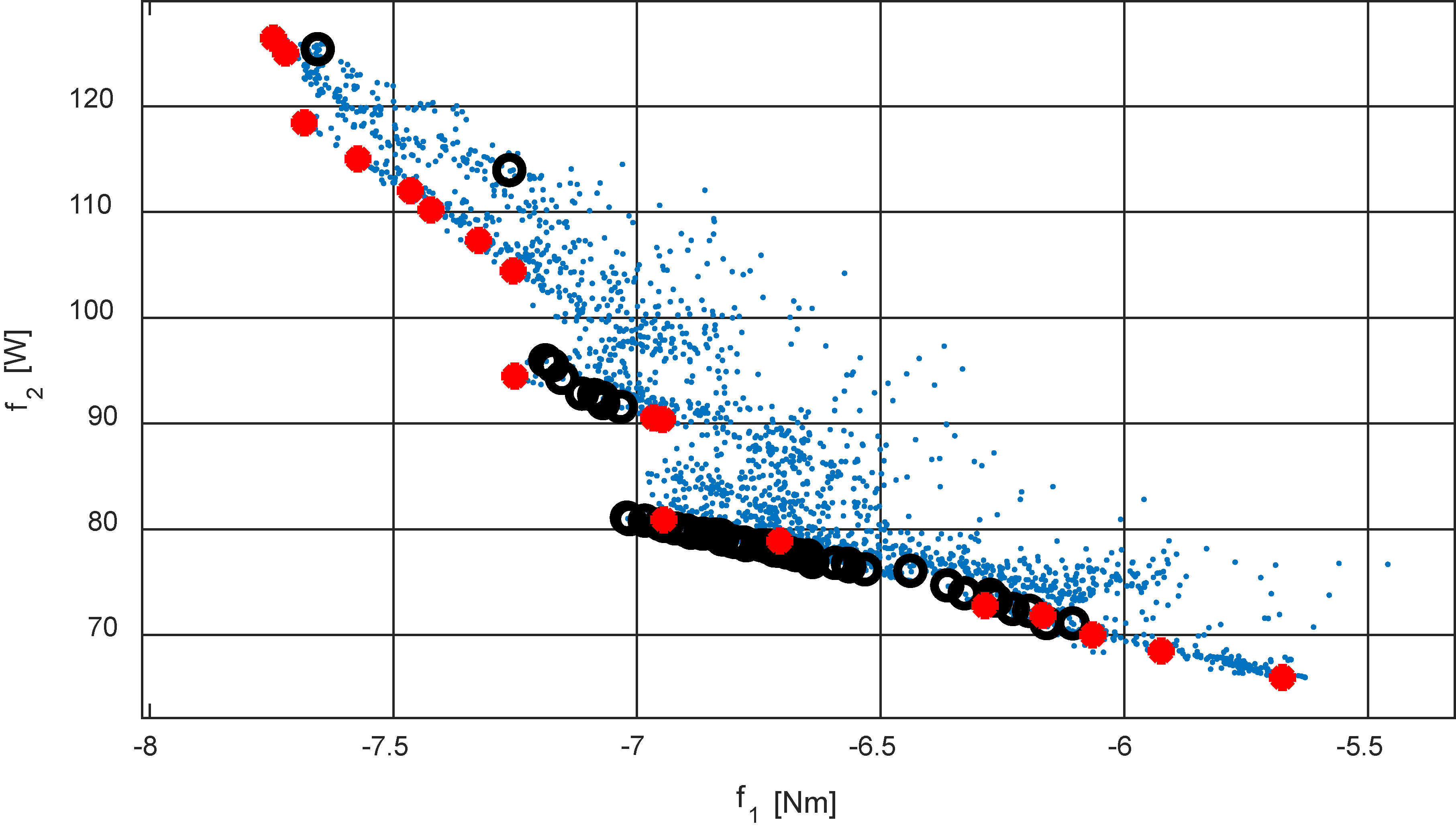
Inductance of commercial SRM at different angles.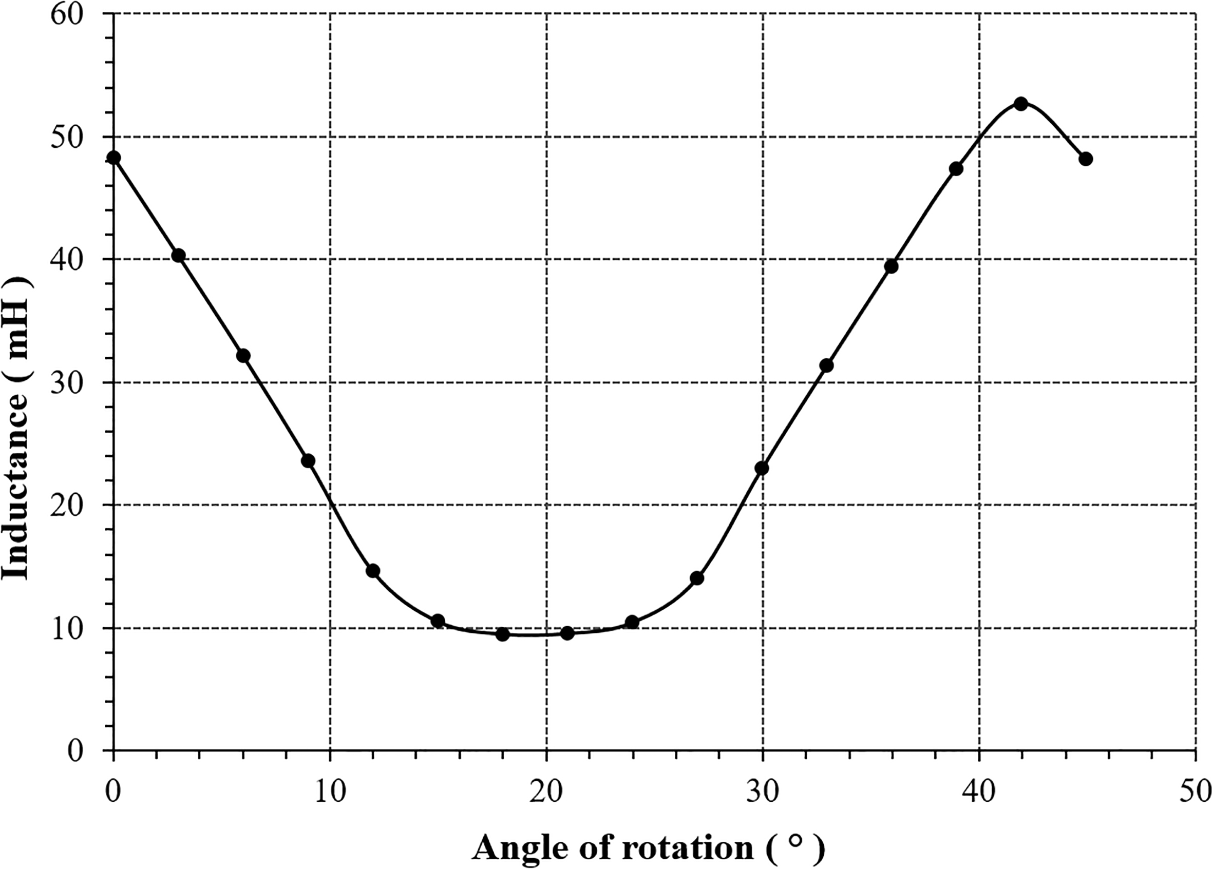
Inductance of SRM model made of soft magnetic composite at different angles.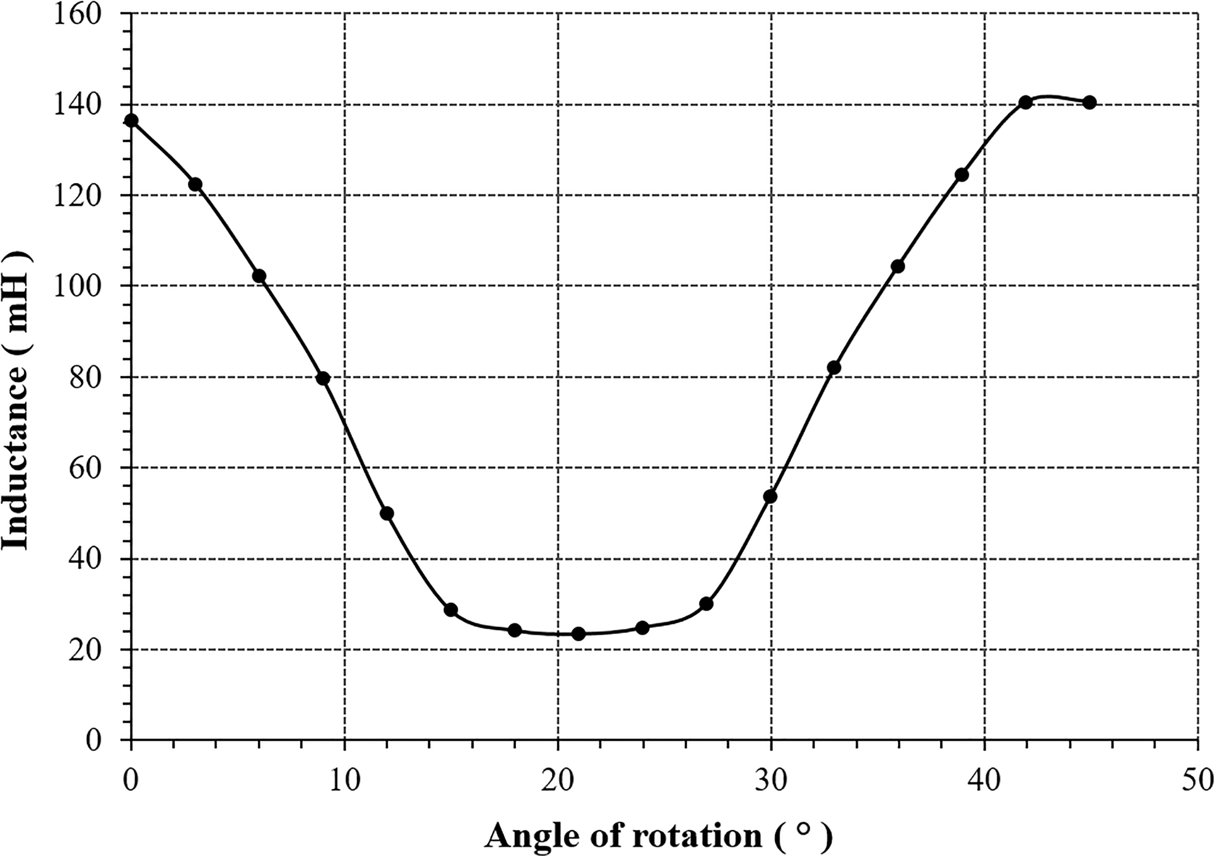
Changes of inductance resemble triangle waveform vs. angle of rotation.
Figure 6 shows a test bench with SRM with magnetic circuit made of soft magnetic composite (left) and stepper motor with supply and control unit (right).
Photo of the test-bench with a switched reluctance motor.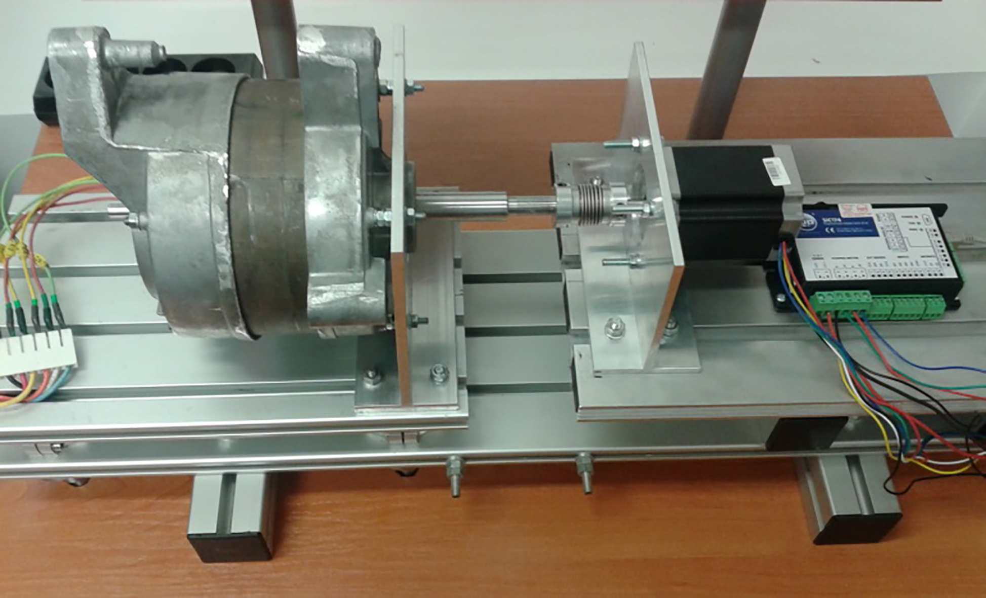
Electromagnetic torque as a function of angle of rotation for the commercial motor for 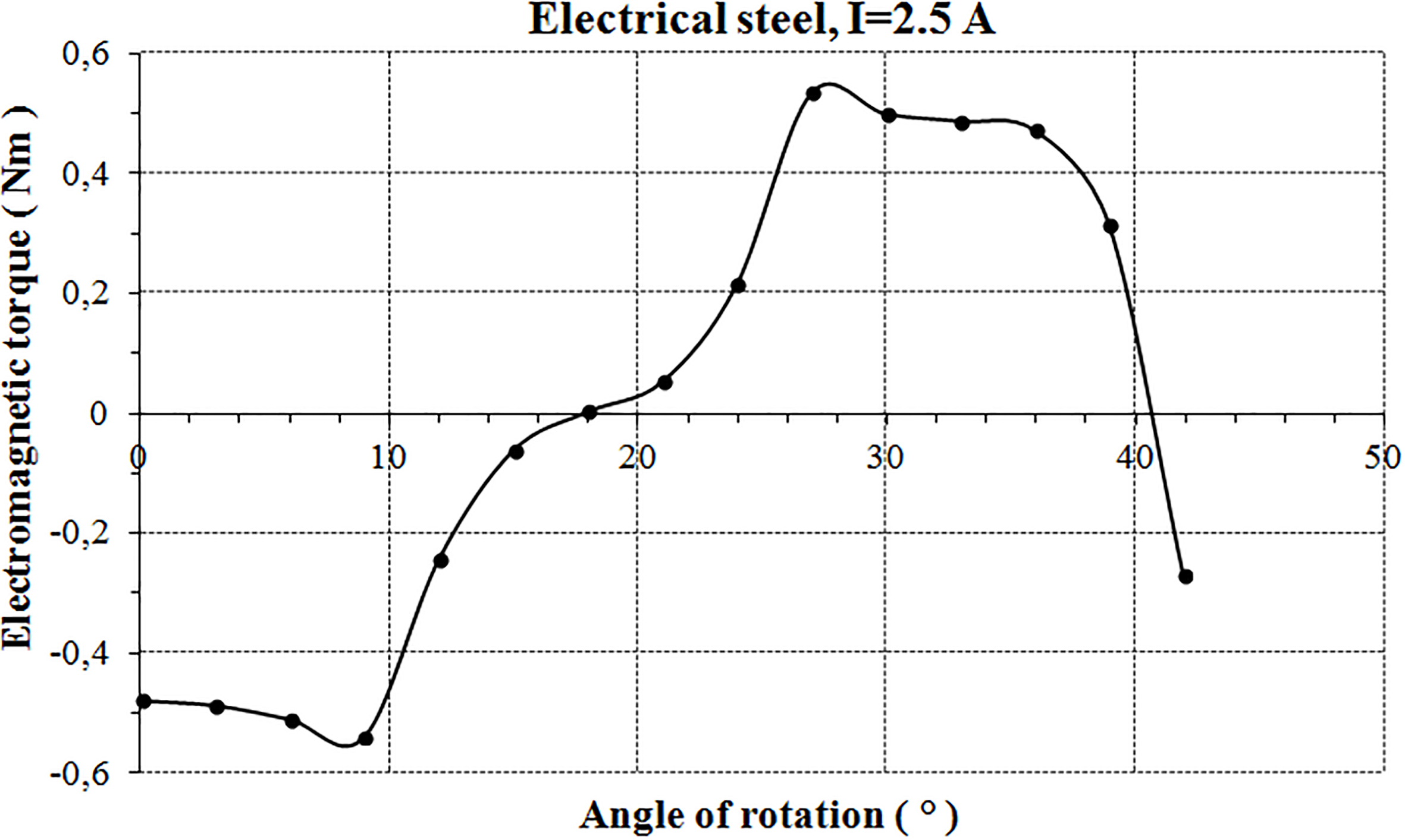
Table 2 shows main parameters of two SRMs.
Electromagnetic torque as a function of angle of rotation for the model motor for 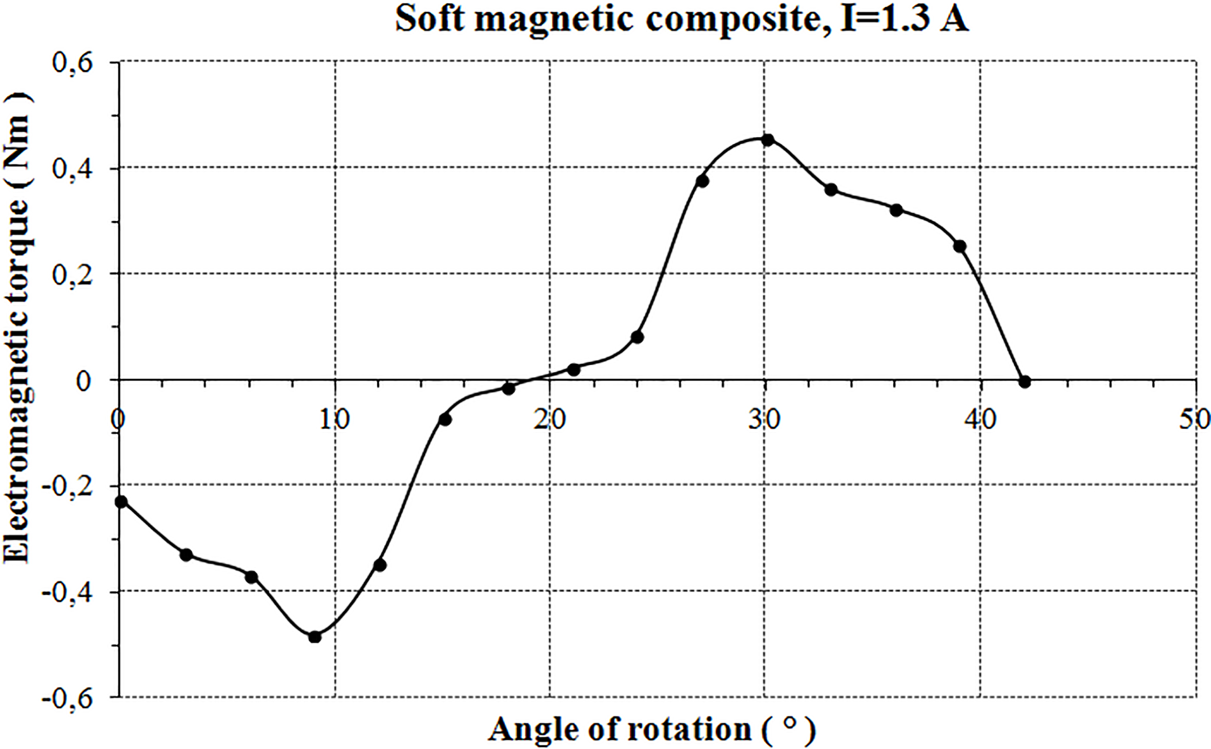
Measurement samples made of Somaloy 700 and Somaloy 700 HR.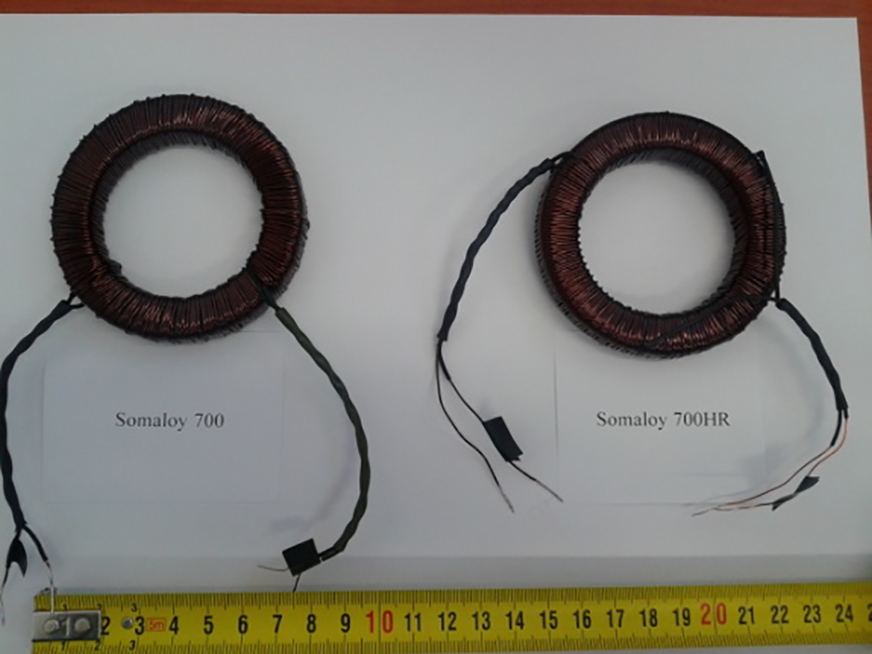
As it can be seen from Table 2, the two types of motor have different resistances and inductances. Commercial motor is supplied by a 120 V AC line, whereas the model motor is supplied by a 230 V AC line. In these two motors the configuration of coils in phases is different.
For comparison, the calculation of the electromagnetic torque
where:
Inductance measurements for each motor were done with the same current and 50 Hz frequency, at
The first motor was a commercial switched reluctance motor, whereas the second was a model with soft magnetic composite core. The results are presented in Figs 7 and 8.
The curves on Figs 7 and 8 show that maximum electromagnetic torque of soft magnetic composite core motor is lower than commercial motor for about 14%.
Amplitude magnetization curves 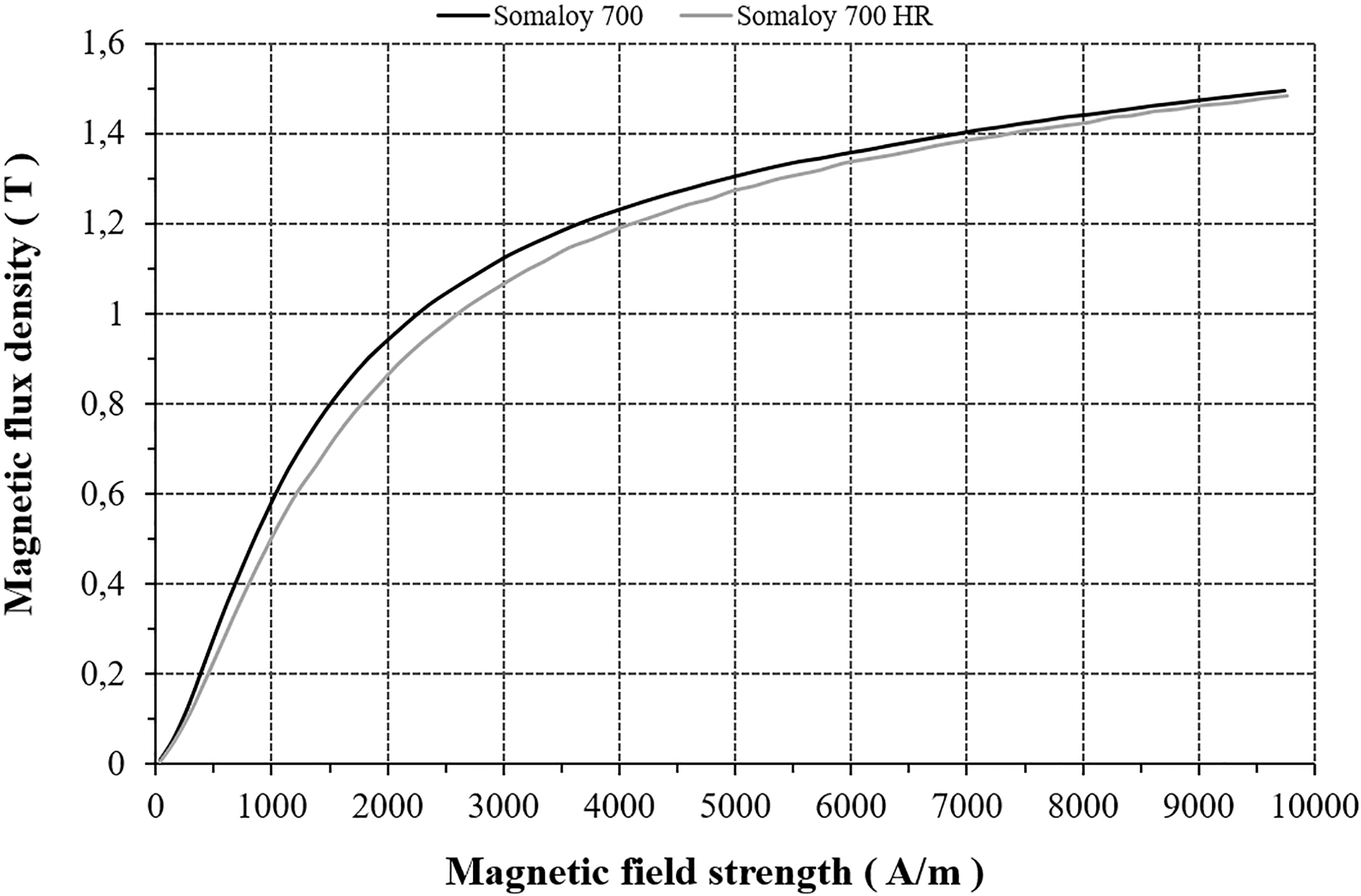
Specific total loss for Somaloy 700 composite.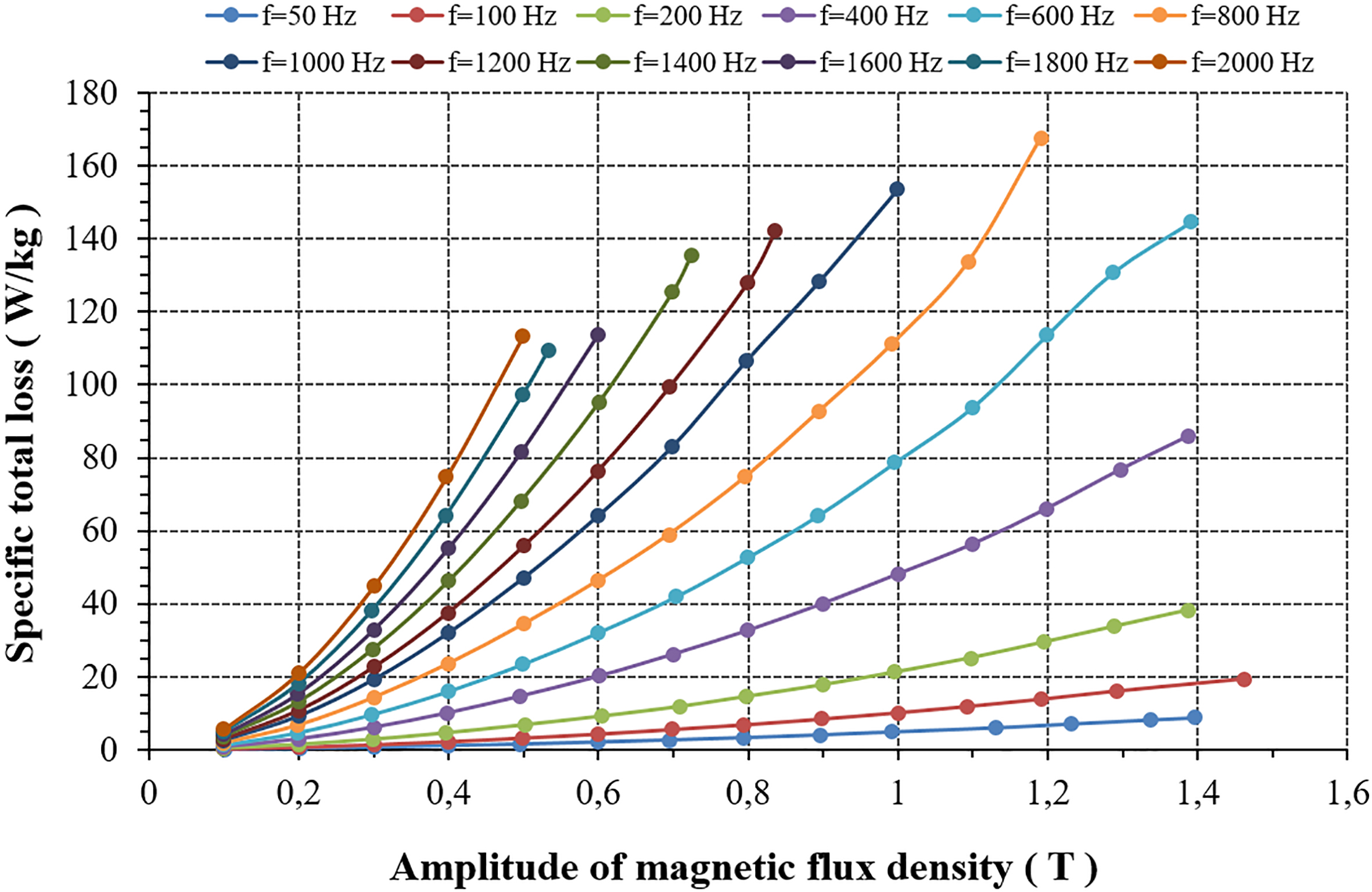
Soft Magnetic Composites that were used in model of switched reluctance motor were measured. Stator and rotor of the motor was made in Tele and Radio Research Institute. In rotor magnetic flux density has lower frequencies than in a stator A stator was made of Somaloy 700 powder whereas a rotor was made of Somaloy 700 HR powder. Measuring samples were prepared according the same technological parameters as parts of the motor. Magnetization curves B
Figure 9 shows prepared samples for measurements and Fig. 10 shows amplitude magnetization curves
Figures 11 and 12 show specific total loss for Somaloy 700 and Somaloy 700 HR composites
Specific total loss for Somaloy 700 HR composite.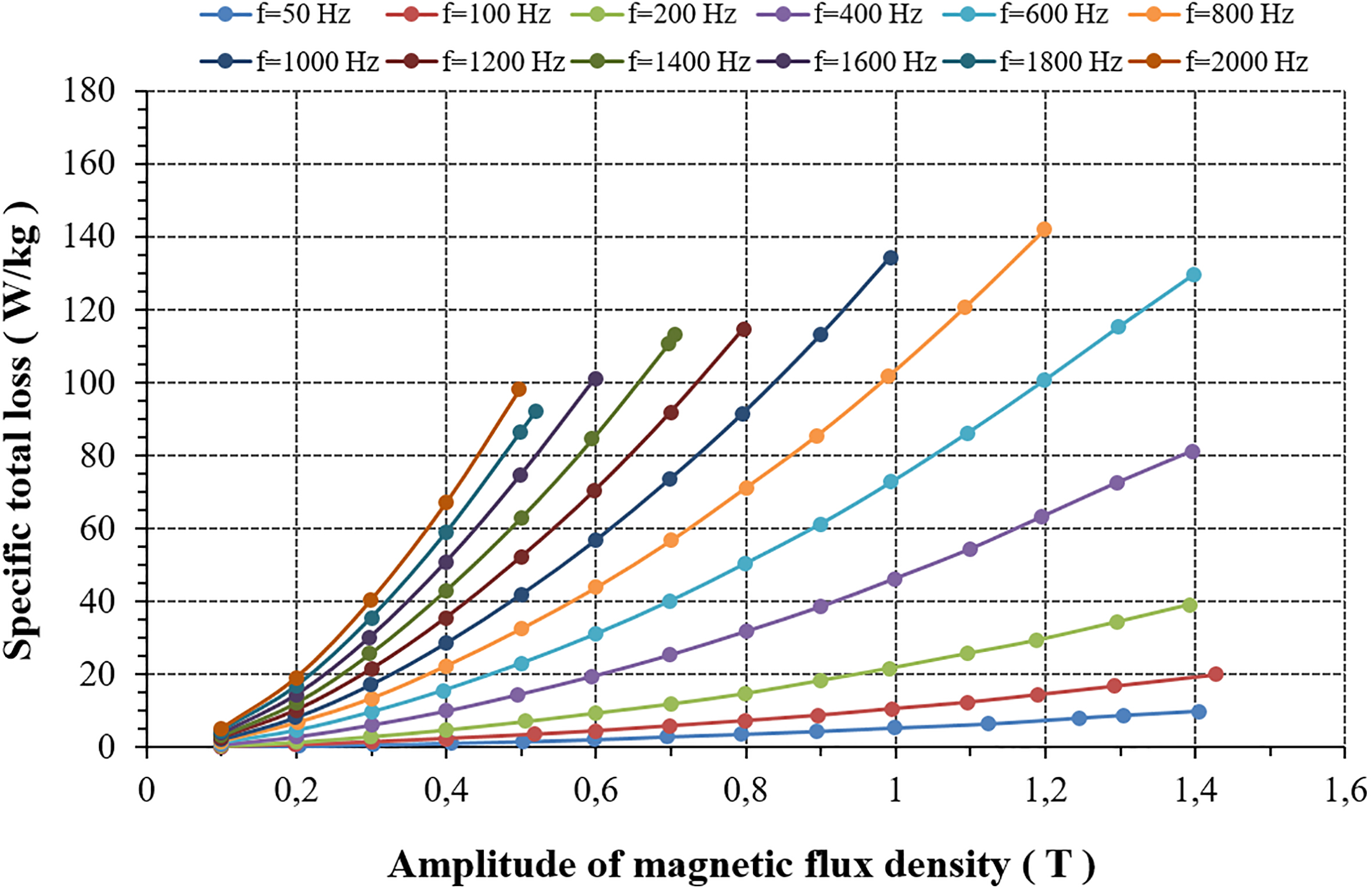
Composites made of Somaloy 700 exhibit better magnetization curve however at higher frequencies they have higher specific total loss than composites made of Somaloy 700 HR.
The generalization of wind-driven optimization algorithm to the multi-objective case makes it possible to approximate the Pareto front of design problems characterized by conflict criteria. Accordingly, the family of optimal shapes trading off torque and power loss of a SRM was successfully identified.
Inductance and resistance measurements conducted for two motors are essential for the next step of work. They will help in the construction of the SR motor optimized in this paper, made of soft magnetic composite core and in the comparison with existing motors that have the same dimensions of the optimized one, as the commercial motor made by Emerson Electric Co.
Measurements of magnetic parameters of magnetic composites made of Somaloy 700 and Somaloy 700 HR powder were also helpful for optimization of a switched reluctance motor.