
Abstract
Magnetic gears can change output-torque and -speed without any mechanical contacts. Therefore, they have a low acoustic noise and vibration, and their maintainability and reliability are high. Especially, a flux-modulated type magnetic gear is expected to be put into practical use because its torque density is higher than that of other magnetic gears. For the practical use, further improvement of torque and losses is important, especially, reduction of eddy current loss in permanent magnets (PMs) due to asynchronous harmonic magnetic fluxes is necessary. This paper investigates an interior permanent magnet (IPM) structure to improve the efficiency by reducing the eddy current loss in PMs. In addition, this paper presents a method for increasing torque of the IPM magnetic gear by changing a position of magnetic-bridge.
Keywords
Introduction
Mechanical gears, which are one of the most important transmission mechanisms, can change speed and torque according to gear ratio. Therefore, they are used in many fields including industry and transportation. However, they have several problems due to mechanical contacts, such as acoustic noise, vibration, and frequent maintenance. Also, the mechanical gears require lubricant to reduce friction and heat generation caused thereby.
Magnetic gears can change speed and torque without any mechanical contacts. Hence, they have low acoustic noise and vibration, high maintainability and reliability, and no lubricant is required. Various types of magnetic gears have been presented in previous papers [1,2]. Among them, a flux-modulated type magnetic gear [3] has attracted interest recently owing to high torque density comparable with the mechanical gears.
Figure 1 shows a basic structure of the flux-modulated type magnetic gear. It consists of an inner and outer rotor with surface-mounted permanent magnet (SPM) and ferromagnetic stationary parts called pole pieces. It works as a gear by modulating the magnet flux due to pole pieces. It has higher torque density than other types because all the magnets of the rotors contribute to transmit torque [4,5].
For practical use, both torque improvement and loss reduction are necessary. In particular, reduction of eddy current loss in permanent magnets (PMs) due to asynchronous magnetic fluxes is indispensable. This paper investigates an interior permanent magnet (IPM) structure to improve the efficiency by reducing the eddy current loss in PMs. In addition, this paper presents a method for increasing torque of the IPM magnetic gear by changing a position of magnetic-bridge.
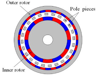
Basic structure of a flux-modulated type magnetic gear.
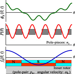
Outside gap flux generated by the inside magnet’s MMF and the pole pieces.
Figure 2 shows the outside gap flux generated by the inside magnet’s magnetomotive force (MMF) and the pole pieces. Assuming that the MMF distribution of the inner PMs is sinusoidal, the MMF of the inner rotor can be written as follows:
Thus, the outside gap flux generated by the inner magnet’s MMF and pole pieces is calculated by the following equation as the multiplication of Eqs (1) and (2).
According to Eq. (3), the flux appearing in the outer air gap has two modulated components (n
s
+ p
h
) and (n
s
− p
h
) in addition to the fundamental component p
h
which is the same as the inner rotor pole pairs. The rotational speed of the modulated components are p
h
ω
h
∕(n
s
+ p
h
) and − p
h
ω
h
∕(n
s
− p
h
), respectively. Therefore, if the outer rotor pole pairs p
l
is selected as either (n
s
+ p
h
) or (n
s
− p
h
), the outer rotor rotates synchronously at the following speed.
In fact, the amplitude of (n s − p h ) is larger than that of (n s + p h ) due to harmonics. Thus, the number of pole pairs of the outer rotor is usually selected as p l = n s − p h .
Characteristic calculation of SPM and spoke-type IPM magnetic gears
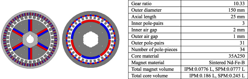
Structure and specifications of two kinds of magnetic gears (left : IPM-type, right : SPM-type).
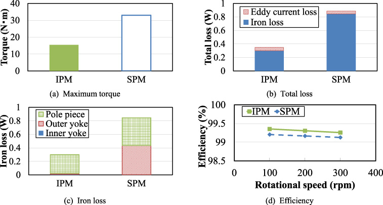
Comparison of the maximum torque, total loss, iron loss, and efficiency of the SPM and IPM magnetic gears.
Figure 3 shows the structure and specifications of the two kinds of magnetic gears. The numbers of pole pairs of the inner and outer rotors are 3 and 31, respectively. Hence, the gear ratio is 10.33, which is given by the ratio of the inner and outer pole pairs [4]. Core material of the pole pieces and rotor are soft magnetic composite (SMC) and non-oriented silicon steel, respectively. The magnet material is sintered Nd–Fe–B.
The spoke-type IPM magnetic gear has the rotor in which inner and outer magnets are embedded as a spoke shape. The rotor has 1 mm wide magnetic bridges on the gap side. In addition, non-magnetic stainless steel is used for the rotor back yoke in order to prevent a short circuit of the PM flux. Both magnetic gears are designed so that the total magnet volume is almost equal, while the total core volumes are different, which are 0.186 L for IPM and 0.245 L for SPM, respectively.
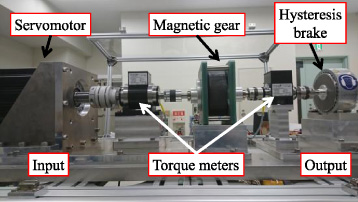
Experimental setup.
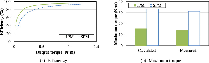
Comparison of efficiency and maximum torque.
Figure 4 shows the characteristics calculated by a three-dimensional finite element method (3D-FEM) using the JMAG-Designer software ver. 18.0. A rotational speed of inner rotor is 300 rpm. Figure 4(a) shows the maximum torque of outer rotor. It is clear that the maximum torque of the IPM magnetic gear is 15.46 N ⋅ m, which is smaller than that of the SPM one. Figure 4(b) indicates the total loss. It can be seen that the iron loss is dominant in both magnetic gears. Also, the total loss of the IPM magnetic gear is lower. Figure 4(c) shows the iron loss. It is understood that the iron loss in the outer yoke of the IPM magnetic gear is remarkably reduced. It should be noted that the iron loss in the inner yoke is remarkably small regardless of the rotor structure, since the flux density of the inner yoke is almost constant, while those of the other parts are fluctuated. Figure 4(d) indicates the efficiency. The mechanical output P
out
and efficiency 𝜂 of the magnetic gear are given by
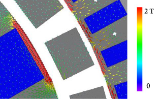
Vector diagram of the magnetic flux density.

Position change of the magnetic bridges.
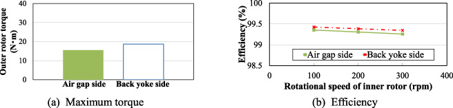
Comparison of the calculated maximum torque and efficiency.
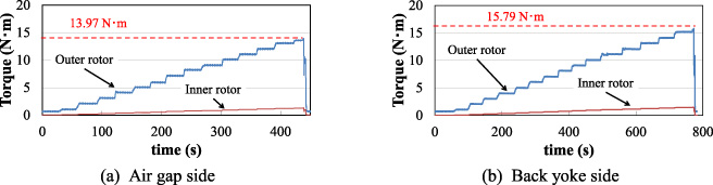
Comparison of measured torque due to differences in the position of the magnetic bridges.
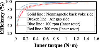
Comparison of the efficiency of the magnetic gears.
Based on the above results, the SPM and IPM magnetic gears, which have the same structure and specifications shown in Fig. 3, were prototyped. Figure 5 indicates the general view of the experimental setup. The prototype magnetic gear operates as a step-up gear on this system. The rotational speed of the outer rotor is regulated at an arbitrary speed by the servomotor. The load torque is controlled by the hysteresis brake.
Figure 6 shows the measured efficiency and maximum torque of the outer rotor. A rotational speed of the outer rotor is 20 rpm. When measuring the maximum torque, the outer rotational speed of the IPM magnetic gear is 1 rpm, and that of the SPM magnetic gear is 3 rpm, respectively. The figures indicate that the IPM magnetic gear has higher efficiency as well as the calculated results and the torque of the IPM magnetic gear is lower than that of the SPM magnetic gear.
Torque improvement of spoke-type IPM magnetic gear
Cause of torque reduction and its countermeasure
Figure 7 shows the vector diagram of the magnetic flux density. It is understood from the figure that part of the PM flux flows through the magnetic bridges, which causes the reduction of effective PM flux contributing to transmit torque. To resolve this issue, the position of the magnetic bridge is changed from the gap side to the back yoke side as shown in the Fig. 8.
Calculation results
Figure 9(a) shows the comparison of the maximum torques calculated by 3D-FEM. The maximum torque of the magnetic gear having the bridges on the back yoke side is 18.7 N ⋅ m, which is larger than that of the magnetic gear having the bridges on the gap side. Figure 9(b) indicates the comparison of the efficiency. It is understood from the figure that the magnetic gear having the bridges on the back yoke side has higher efficiency.
Experimental results
Figures 10(a) and (b) show the comparison of measured torques. A rotational speed of the inner rotor is 300 rpm. The maximum torques of the magnetic gear having the bridges on the gap side and the back yoke side are 13.97 N⋅ m and 15.79 N⋅ m, respectively. As with the calculation result, the magnetic gear having the bridges on the back yoke side has larger torque. However, the calculated and measured values are different each other.
Figure 11 indicates the comparison of the efficiency of the magnetic gears when a rotational speed of inner rotor is 100 rpm and 300 rpm, respectively. It is understood from the figure that the magnetic gear having the bridges on the back yoke side has higher efficiency.
Conclusion
This paper investigated an interior permanent magnet (IPM) structure to improve the efficiency by reducing the eddy current loss in PMs. In addition, this paper presented a method for increasing torque of the IPM magnetic gear by changing a position of magnetic-bridge.
It was clear that the IPM magnetic gear has higher efficiency in comparison with the SPM magnetic gear, but the torque is inferior. To improve the torque, the position of the magnetic bridge is changed from the gap side to the back yoke side. As a result, the torque and efficiency were improved compared to the conventional IPM magnetic gear.
Footnotes
Acknowledgements
This work was supported in part by the WISE program for AI Electronics, Tohoku University.