
Abstract
The paper deals with analysis of vibrational behavior of induction motor using the combined approach linking the finite elements method (FEM) applied to modelling of magnetic and mechanical phenomena in the motor with its modal description in spectral domain. Results of investigations presented in this paper proved that relatively small rotor axis misalignment against stator leads to visible vibration if forces resulted from this effect have frequency close to rotor bending resonance. Paper contains a rigorous description of all steps in analysis with a special attention paid to details of numerical approach both in FEM and in spectral consideration. Results of theoretical investigations were confirmed by measurements.
Introduction
The induction motors are widely used in many household devices like laundry machines, dryers and others. Nowadays they have the three-phase supply from a power converter enabling the smooth control in a wide range of an angular velocity. Their application inside devices having relatively large and thin housing in connection with the possibility of non-centric shaft load makes them a potential source of vibration and accompanying acoustic pollution.
Vibration and acoustic noise emitted by induction motors has been studied almost one hundred years. Starting from pioneering Jordan work [1] and its followers [2–4] dozens of papers were afterwards written containing different approaches to modelling, measurements and other designing problems related to these machines [5–7]. The substantial development of numerical modelling techniques both in electromagnetic and mechanical domains caused that finite elements approach is the basic tool for the solution of vibration of electromechanical devices [8,9].
Excessive vibration is mainly mitigated by the correct choice of the number of stator and rotor slots relative to the number of pole pairs required together with their mutual skew. Such rules are well known and they may be found in [2,3]. For medium and high power motors there is no problem to find these numbers, the eventual problem comes from rather low values of resonant frequencies of the stator structure which may be too close to frequencies of exciting forces. The oppose situation arises in small machines where the stator resonances appear quite far in the frequency spectrum but the available slot numbers are very limited due to small size of these motors. Up to some extent the vibration may be reduced using the appropriate control strategy [10] or applying the carefully designed damper windings connected with the resonance circuit [11]. The magnetic stress in the air gap is assumed to be the input quantity forcing vibrations, however, magnetostriction effects present in stator core may also contribute [13,15]. Some results concerning other types of AC machines can be directly applied when vibration of induction motors are of interest [12,14].
The paper presents combined analysis of vibration caused by magnetic forces in three-phase induction motor of power 1.5 kW supplied from network and inverter. The finite elements technology is used in magnetic and vibrational calculus by means of commercial software (Magnet and ANSYS). The results are obtained with the modal approach specified for magnetic forces definition and also for calculations of the vibration response.
Motor description
Analyzed motor is intended for a laundry machine what explains a specific shape of its housing consisting of two separate bearing plates connected with a pair of handles. The stator is equipped in a single-layer winding, the rotor has an aluminum cage with the slot skew of 1.15 stator slot pitch. The outlook of the motor is shown in Fig. 1 and basic data are given in Table 1.
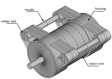
Outlook of model geometry of analyzed motor.
Motor data
The non-linear 2D solution of the magnetic field distribution in terms of magnetic vector potential in the cross-section of the motor was obtained in two ways. Firstly, the harmonic solver was applied at no-load state and forced voltage on terminals of the motor. Secondly, the time-stepping with motion for the same conditions was used. The computing time was, of course, very different. The time stepping required about 40 min but the nonlinear harmonic approach took few seconds only. Results observed on the single field plot were quite similar, e.g. magnitude of flux density in stator tooth was 1.65 T for time stepping and 1.7 T for the harmonic solution. Also the instantaneous pictures of the flux density distribution along the air gap in both cases were comparable. The exemplary results are displayed in Fig. 2. The main difference between these approaches concerns the spectral content of currents induced in the rotor bars. The time harmonic solution by definition gives the single frequency only resulting from the input value of the rotor slip. When the time stepping connected with the rotor motion is solved the additional time changes of the rotor flux linkage appear caused by the variable permeance of the air gap which enrich significantly the time profile of the rotor currents. Exemplary distribution of the rotor current within one period of the supply is shown in Fig. 3.
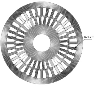
Instantaneous flux density distribution in motor cross-section at no-load.
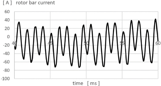
Rotor bar current versus time at no-load resulting from 2D time stepping with motion.
The analyzed motor has a small air gap, therefore, the contribution of the permeance harmonics in the 2D solution is substantial. Their reduction in a real motor is obtained by the rotor slot skew which has no chance to be applied in a 2D model. It is possible to build the 3D model having this property but the computing time of the 3D time-stepping would be unreasonable. Therefore, the simplified algorithm using the modal skew factor 𝜉
sr
was applied which is given by
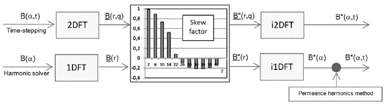
Smoothing algorithm of flux density distribution in air gap of induction motor.
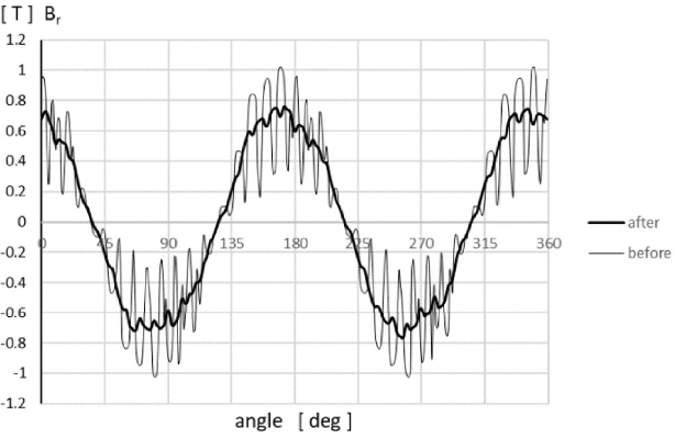
Results of application of smoothing algorithm on radial component of flux density distribution in air gap of induction motor at no-load, centric rotor.
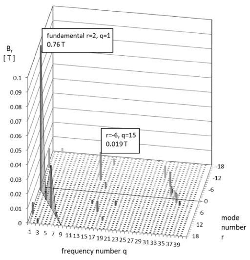
Single-sided mode-frequency spectrum of radial component magnitude of flux density distribution in air gap of induction motor at no-load, centric rotor.
Apart the case of centric rotor analysis two types of the possible eccentricity were also investigated. Firstly, the constant misalignment of 60 μm between stator and rotor axes was applied. Secondly, this misalignment was sinusoidally varying in time along chosen axis with the frequency equal to the rotational speed. In both mentioned instances the angular step of rotor rotation was set to 1 degree. The results of calculations having the form of space-time [360 × 360] arrays of flux density vector along the air gap were extracted for further post-processing. The time stepping method has also some limitations connected with the requested computational effort. Number of steps N in time domain results from parameters of DFT analysis given by Shannon theorem
The presence of any eccentricity must trigger the forces F of so-called magnetic pull acting simultaneously on stator and rotor of the machine. It may be calculated from the magnetic stress distribution σ
ij
(x, y) on the closed surface S marked out in the air around the stator or rotor. The value of this force equals to (index summation applied)
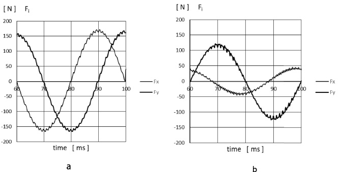
Time functions of Cartesian components of magnetic pull in induction motor at no-load, (a) stator versus rotor axes misalignment of 60 μm, (b) rotor axis 60 μm oscillation with frequency 25 Hz along y direction.
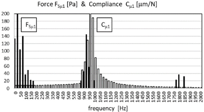
From the point of view of affecting the amount of resultant vibration, only the forces of the lowest orders matter. That statement concerns both radial and tangential components of forces applied to stator teeth tips. It should be remembered that magnetic attraction forces on boundary iron/air by definition have the normal component only. The resultant displacement profile of the outer yoke surface is created mostly by the bending deformations of the yoke. This effect in a hollow cylinder arises when the balanced set of moments of forces is applied to its structure. It comes from alternating (in space) radial or tangential magnetic stress integrated over surface of their existence and transmitted through the teeth. The radial stress forms a continuous distribution along the air gap but the tangential stress has a shape of narrow peaks appearing under slot openings only. Besides, the tangential forces are substantial at rated load. The analysis presented here concerns the no-load case what allows to neglect the tangent forces and reduces the force spectrum to orders −12 ≤ 𝜈 ≤ 12. Quantitative assessment of this assumption is given in the next chapter where values of modal compliances of low-order modes are presented.
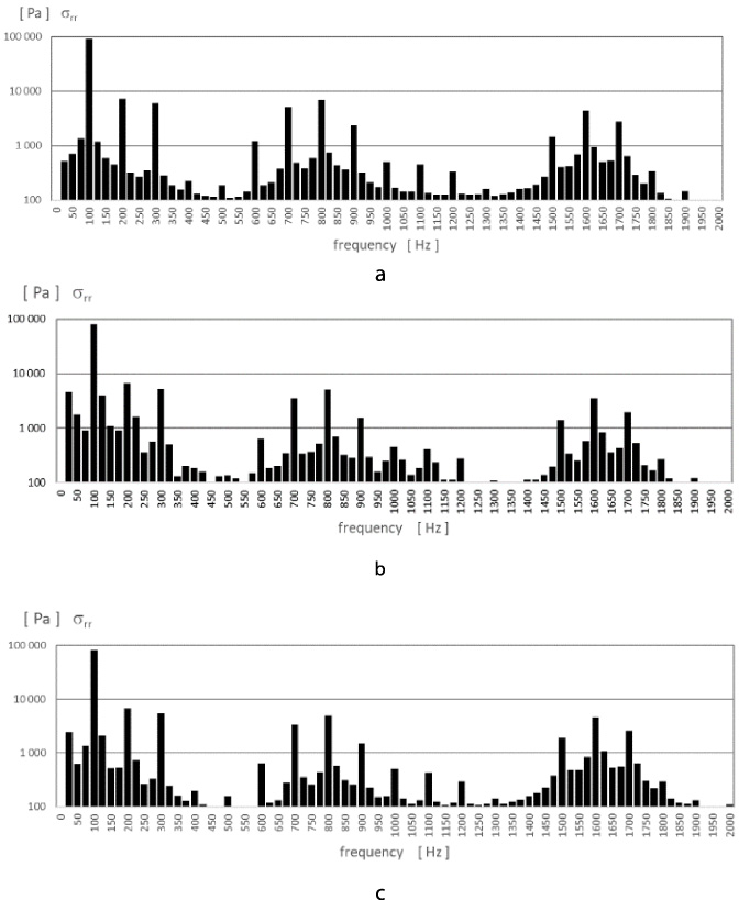
Frequency spectra of spatial rms values of magnetic forces in induction motor at no-load, (a) centric rotor (b) stator versus rotor axes misalignment of 60 μm, (c) rotor axis 60 μm oscillation with frequency 25 Hz along y direction.
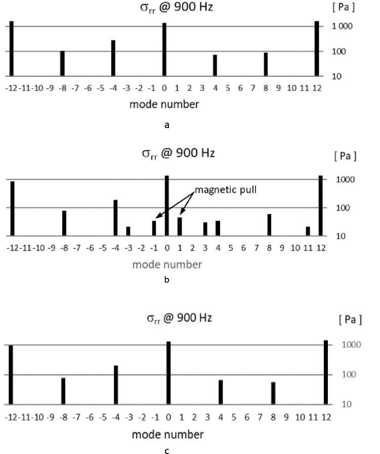
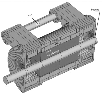
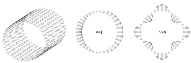
Modal spectra of magnetic forces having frequency 900 Hz in induction motor at no-load, (a) centric rotor (b) stator versus rotor axes misalignment of 60 μm, (c) rotor axis 60 μm oscillation with frequency 25 Hz along y direction.
For illustration purposes the frequency spectrum of spatial rms values FSμ was calculated following the Parseval theorem as
The cross-section of the mechanical model of analyzed motor and boundary constraints applied in calculations are shown in Fig. 10. Steel parts of the motor (housing, stator core, shaft) are isotropic. The windings and bearing area have a distinct transverse isotropy only. The isotropic rotor material has stiffness of the steel but its density is fictious resulting from the sum of the cage and core mass inserted into real volume. The conversion of the force excitation from magnetic surface forces FSμ𝜈 having the mode 𝜈 and frequency number μ into structural discrete domain requires the definition of nodal force in structural mesh. The amplitude of nodal force
Section of structural model of induction motor.
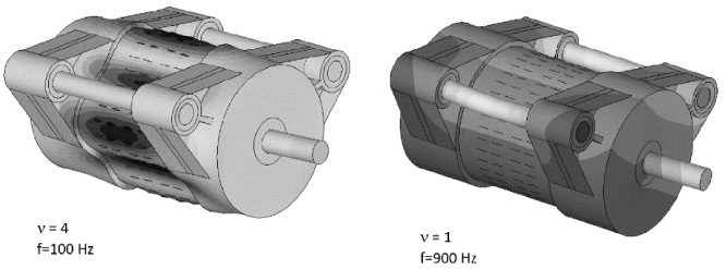
Nodes of structural mesh on inner stator surface and instantaneous distributions of forces having mode 𝜈 = 1 and 𝜈 = 4.
Some comments are necessary on forces applied to rotor. When the mode number 𝜈 > 1 the overall sum of nodal forces applied to both the stator and rotor amounts to zero. The stator yoke having the form of a relatively thin hollow cylinder is deformed by bending moments but the rotor has no holes inside and it is compressed/elongated only. Therefore, in view of difference between bending and compression stiffness one may assume that rotor deformation is negligible. Completely different conditions exist when 𝜈 = 1. The magnetic pull applied to the rotor is balanced by reaction forces occurring in the support area situated on the stator and transmitted to the rotor via bearings. Now the elastic shaft may be bended what means that rotor core and cage move following the shaft deformation in a form of a rigid body. It allows to represent the rotor pull by the single radial nodal force counteracting the distributed stator pull and having the same rotation. The value of this force can be obtained from ((12)) setting N S n eff = 1. The dynamic behavior of the motor depends on values of natural frequencies and is tightly connected with the shape of natural modes. Figure 12 presents chosen natural modes having low frequencies and simultaneously exhibiting vibration in the plane perpendicular to the rotation axis. The modes containing first order bending deformation of the rotor belong to the frequency range 800–1000 Hz, the lowest stator bending mode 𝜈 = 2 has the frequency f = 2555 Hz. The natural mode of order 𝜈 = 4 which dominates in the force spectrum was not detected below 6000 Hz.
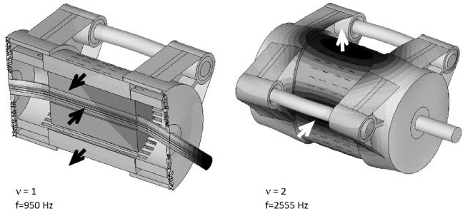
Chosen natural modes of induction motor, shaded map shows modulus of displacement.
All material properties in the model are constant, therefore, it is possible to calculate separately for the each mode the vibration response of the motor structure assuming the unit value of the nodal force magnitude. Such a treatment is often met [16] and gives the value of modal compliance Cμ𝜈 relating the magnitude of the outer displacement of the motor surface to the magnitude of nodal force. Values of the compliance defined in this way for the few lowest mode numbers and frequencies of interest are given in Table 2.
Modal compliances
Dynamic modal displacement Cμ𝜈 patterns are now easy to get. Having the mode-frequency spectra of surface forces FSμ𝜈 and motor compliance Cμ𝜈 it is possible to calculate values of Cμ𝜈 by simple extension of ((12))
Frequency spectra of the first mode of surface forces
Chosen instantaneous shapes of forced vibration of induction motor, shaded map shows modulus of displacement.
Vibration of investigated motor was measured by the set of piezoelectric accelerometers mounted on the stator circumference as it is shown in Fig. 15. The simultaneous acquisition of signals from all gauges enabled separation of instantaneous shapes of vibration for particular frequencies. The shapes of two components having frequency 100 Hz and 899 Hz are also displayed in this figure. The first one with the doubled network frequency forms the rotating wave of the fourth order. Its irregular picture (different shapes of positive and negative half-waves) results from the number of accelerometers because twelve gauges cannot accurately map the shape of wave having four periods in space. The second one presents the almost pure oscillation of the stator core along some axis. Its frequency f
′
exactly matches the expression
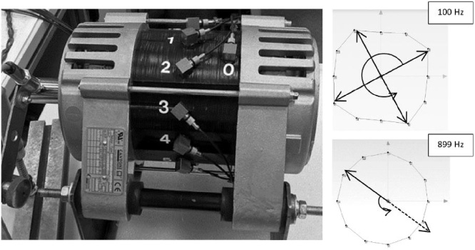
View of test stand for vibration measurements of induction motor with instantaneous shapes of radial vibration field.
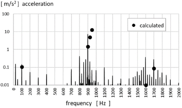
Measured and calculated acceleration spectra (rms) of outer surface of induction motor at no-load.
The emitted acoustic pressure is proportional to the acceleration patterns on outer surface. The measured spectrum of acceleration is shown in Fig. 16 where few values coming from calculations at important frequencies were also added. Commenting differences between theoretical and experimental values we should keep in mind that spectral components of flux density in the air gap responsible for forces around 900 Hz are of order of 10 mT. Besides, the change of modal compliance in 1 or 2 percent may cause the changes of vibration magnitudes in this area in amount of dozens percent because of the closeness between excitation and resonance frequencies. The small frequency shift of Δf between calculated and measured spectral components of forces resulting from stator slotting may be caused by the incomplete decay of transient effects in rotor currents. Also the value of eccentricity in this analysis equal to 24% of the air gap size was arbitrary.
Results of investigations presented in this paper proved that relatively small rotor axis misalignment against stator leads to visible vibration if forces resulted from this effect have frequency close to rotor bending resonance. Probably it is not possible to avoid the eccentricity in a mass production of electric motors. The given construction of the motor has so-called first and second critical rotor frequencies at known points of the spectrum. Therefore, the choice of stator and rotor slot numbers should also to take them into account. This is particularly important for motors designed for drives with a wide range of a variable speed.
Footnotes
Acknowledgements
The research was granted in part by The European Regional Development Fund no. POIR.04.01.04-00-0002/16-00.