






Abstract
This paper aims to propose a method to determine the temperature rise and rated capacity of induction motors under different working systems. A dynamic mathematical model, a 3D temperature field model, and finite element method are used to analyze the electromagnetic loss and transient temperature rise, respectively. The influence of the motor starting process on the temperature rise is taken into account, which resolves the complex loading of transient heat source. The maximum allowable running times for the motor operating with different overloads are determined. The relationship between the motor output power and the allowable running time is obtained, and it provides a basis to determine the rated capacity of motor under S2 working system. The relationship between the motor output power and the temperature rise under different load duration rates is also obtained and provides reasonable evidence to determine the rated capacity of the motor under S3-working system.
Introduction
Three-phase induction motor is widely used in many applications and drives different loads to satisfy the work requirement. It is able to run for a short time under overload condition due to its large heat capacity. If it is ensured to operate safely and reliably under a variety of working systems, the production efficiency of the motor is greatly improved. In fact, it is difficult to determine the rated power of a motor under different working systems. If the load does not match with it, the motor may be underutilized or heated, and even be burned under very heavy load. Valenzuela et al. pointed out that the motor designers and standard-setters did not pay enough attention to the method for determining thermal rating of motor when the continuous-duty motor is operating under a short-time load, a continuous-cycle load or an intermittent-cycle load, and proposed a simplified method based on the thermal homogeneous model of motor to calculate the equivalent rating data of continuous-duty motor under short-time and cycle working systems [1], but this method can provide an accurate prediction only when the thermal time constant is available. Veysel et al. evaluated the temperature rise of motor according to the motor size and the i 2 t characteristic of conductor when the motor operated under different overloads, and analyzed the maximization problem of the short-time torque capacity [2]. Based on finite element method (FEM) and computational fluid dynamics (CFD) theory, Nategh et al. calculated the relationship between the temperature rise and time when the motor operated under a continuous load and a cyclic load, respectively [3]. Pei et al. calculated the temperature field of the motor under short-time overload and cyclic operation conditions, and analyzed the heat dissipation effect of the motor based on FEM and CFD coupling model, and then obtained the temperature rise of the motor under different overloads [4].
Boglietti et al. established the lumped thermal circuit model and analyzed the heat conduction between winding and core of motor in a short-time transient heating process [5,6], and furthermore proposed a calibration method of the lumped thermal circuit model according to the experimental results of the short-time transient and steady-state temperature rise of motor [7]. As the S1 working-system motor is required to operate under a short-time and a cyclic overload, Boglietti et al. also calibrated the parameters for thermal circuit model of an industrial motor via experiment, and predicted the stator-winding temperature rise of motor under transient overload [8,9]. Boglietti modified the calculation model of temperature rise based on experiments, which is great significance for the development and design of motors with new structure. However, the loads driven by motor are usually varied according to the practical applications, so it is difficult to carry on the experimental tests to ensure enough test data for calibrating the lumped thermal circuit model.
FEM is usually used to study the effect of working systems on the motor’s performance [10–13]. For example, Li et al. obtained the winding temperature rise of a motor under a short-time working system with FEM [10]. Liu et al. used FEM to study the influence of long-time, short-time cyclic or short-time high-overload working systems on the temperature rise of a motor under different ambient temperatures [11].
Many researches show that most of the methods for determining the rated power of the motor under different working systems are based on experiments, and the temperature rise is usually used as the standard to define the motor capacity. However, it is actually difficult to carry out the on-site experimental test. Although the rated power of motor under different working systems can be determined according to the power growth coefficient, it is difficult to ensure reasonable accuracy. In order to obtain the temperature rise, the simplified thermal circuit model are usually used, and sometimes FEM or lumped parameter method are also applied. But the effect of working systems on the temperature rise of motor is still inadequately studied, which makes it difficult to determine the rated power of motor under different working systems quickly and reasonably. To solve this, the transient temperature rise of motor under different working systems is studied in this paper, and the influence of working systems on temperature rise is obtained, which provides the evidence for determining the rated power of motor under different working systems.
Establishment of domain model and boundary conditions
Prototype parameters and domain model
When a continuous working-system motor operates with a short-term load or cyclic load, it is difficult for the motor to reach a stable temperature rise. When the rotational inertia of load is much larger, the starting time is longer and the starting current is rather higher, which aggravates the heating problem in the starting process of motor. Therefore, in order to determine the rated power of motor under different working systems, it is necessary to ascertain the temperature rise of motor under transient states. In this paper, a three-dimensional (3D) transient temperature field of a squirrel-cage induction motor (S1 working system) is analyzed. The basic parameters of the prototype motor are shown in Table 1. According to induction motor structure, a 3D temperature model of the induction motor is built, as shown in Fig. 1.
Parameters of the prototype motor
Parameters of the prototype motor
Winding loss
The dynamic model of induction motor as shown in (1)–(3) is used to analyze the starting process [14]. According to the analysis and calculation of the starting process, the stator current for 1 and 1.5 times rated load driven by the prototype motor are shown in Fig. 2. It can be seen that, at the beginning of the starting process, the starting current is very high and is about 6 times of the steady-state current, whilst the current reaches a stable value when the motor starts up to about 1.5 s.
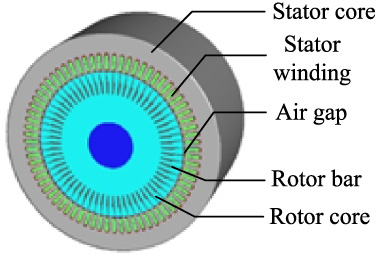
3D model of the motor.
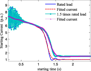
Starting current varying with time.
Since the stator winding of the prototype motor is wound winding, the skin effect of winding is ignored. The winding loss of prototype motor is defined as (4).
Considering the motor transient process, the winding loss is related to the starting current. According to the calculated starting current, the Gaussian fitting method is used to determine the fitting function and the fitting curve is shown in Fig. 2. The fitting functions of the multiples of the stator current at 1 and 1.5 times rated load are described as (5) and (6), respectively.
The iron loss is obtained according to the calculated magnetic density by FEM [15] and is defined as (7).
The value of steady-state loss is 1125 W. The motor core loss mainly depends on the alternating frequency of magnetic flux, core material and magnetic flux density. According to E = 4k NM ⋅ k dp ⋅ f ⋅ N ⋅ Φ, the induced electromotive force (E) is almost constant when the end voltage keeps constant. So although the loads varied, the core loss stays the same as long as the magnetic flux (Φ) and the core magnetic density remain unchanged.
The 3D heat conduction model of the temperature field in solution domain is followed as below.
The heat dissipation coefficient (𝛼1) of the outer circle boundary of the stator core is presented as follow [16,17].
The heat dissipation coefficient (𝛼2) of the end face of the stator core is defined as below.
The heat dissipation coefficient (𝛼3) of the end face of the rotor core is followed as below.
Temperature rise under rated load
Based on the motor loss and heat-dissipation boundary conditions of motor under the rated load of S1 working system, CFD was used to simulate the temperature field of the motor [18,19] and the overall steady-state temperature rise distributions of the stator and rotor are calculated, respectively, as shown in Fig. 3. The influence of the rotor core loss due to its small value is neglected during the simulation. The rotor core has a large heat capacity and a good radial thermal conductivity, and the heat generated by the rotor bar loss can be better conducted to the rotor core. So the overall temperature gradient in the rotor is very small, and the temperature of the inner diameter is much lower than that of the outer diameter in the rotor core.
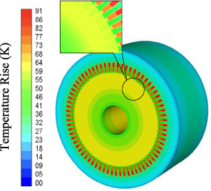
Steady temperature rise of motor under rated load.
In order to simplify the calculation model, the motor shell is not taken into account in the proposed model. The shell surface is connected with the external wind path for convection heat dissipation. The reduction value of the outer circle area of the stator core versus the shell surface area is approximately equal to the reduction of the heat dissipation effect of the core compared with that of shell due to the heat conduction between the core and the shell, so that (9) is applied to the outer surface of the core as boundary condition. As the heat generated by stator core can be well dispersed via the motor shell, the temperature rise of stator core is low. The loss of stator windings is very large to cause a large amount of heat. In addition, the thermal conductivity of stator slot insulation is far lower than that of core materials, leading to the high temperature rise of stator windings.
The load experiments of motor are carried out by the twin trawling of two motors as shown in Fig. 4, and platinum thermal resistance is used to detect the temperature rise of motor. The temperature data is collected by the digital motor test system and read into the computer. The temperature rise of stator winding is measured under rated load.
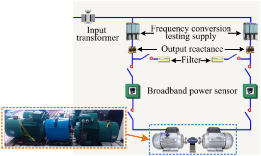
Load experiment system.
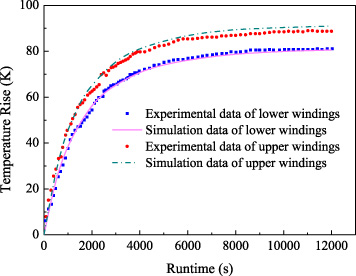
In steady state, the highest temperature rise in the motor appears at the lower winding of the stator, which is 91 K, as shown in Fig. 5. Figure 5 also shows the comparison between the calculated values of the temperature rise in the upper and lower stator windings of the prototype motor and the experimental ones of the temperature rise in the stator windings. The simulation results are nearly consistent with the experimental ones, proving the correctness of the proposed model and the solution method.
Comparison between simulation and experimental results.
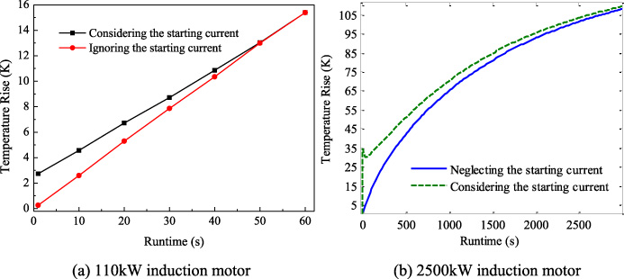
When the prototype motor drives 1.5 times rated load and runs for 1 min, the stator temperature rise as shown in Fig. 6(a) tends to be the same regardless of whether the starting current is considered or not during the calculation process. As the starting time of the prototype motor is very short, the starting current mainly affects the temperature rise in the initial starting period. The proposed method is also used to analyze the temperature rise of a 2500 kW medium high-voltage induction motor with an axial-radial mixed ventilation structure, when the motor drives 1.2 times rated load. The calculated stator temperature rises are shown in Fig. 6(b) by considering and ignoring the effect of staring current, respectively. It can be seen that the starting current has a great influence on the temperature rise for a long time when the motor has already started. The proposed method takes into account the effect of starting current on the temperature rise, especially for the motor with large rotational inertia and long starting time.
Influence of starting current on the temperature rise.
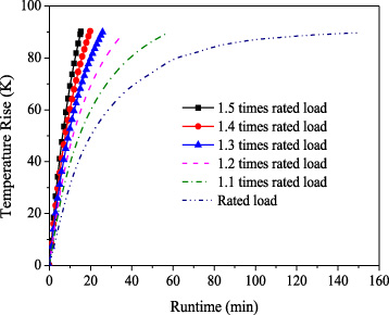
The maximum steady state temperature rise of the prototype motor under rated load and S1 working system is considered as the temperature rise limit in this work. The 1.1, 1.2, 1.3, 1.4 and 1.5 times rated loads are used as loads driven by the prototype motor under S2 working system. The transient temperature rise of the S2-workding-system motor is calculated to determine the safe runtime of the motor under different overloads. Figure 7 shows the variation of the highest temperature rise of stator winding against runtime.
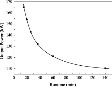
It can be seen from Fig. 7 that when the calculated motor operates under rated load of S1 working system, it will run for about 140 min to reach the thermal stable state. At this time, the temperature rise of the stator winding of the motor approaches 91 K, which is taken as the temperature rise limit of the motor. When the motor is overloaded to different degrees, the operating time corresponding to the temperature rise limit is 60 min (1.1 times rated load), 36.5 min (1.2 times), 25.8 min (1.3 times), 19.8 min (1.4 times), and 15.3 min (1.5 times). When the motor operates in S2 working system, the output power of the motor should be reasonably determined under a specific short running time to prevent the motor temperature rising too high. According to the research in this paper, the relationship between the motor running time and the allowable output power is obtained when the prototype motor is applied to the S2 working system, as shown in Fig. 8.
Highest temperature rise varying with runtime under different loads.
Relationship between the rated output power and runtime.
When the S1-working-system motor operates under the S3 working system, the output power of motor can be enhanced to meet the various production requirements under the condition that the starting capacity and the temperature rise can be ensured. During the starting process, the prototype motor can drive up to 1.8 times rated load, and the overload capacity of the motor can be guaranteed in this work.
According to the government standard of GB755 in China, namely basic technical requirements of rotary motor, the cycle of operation of the motor under S3 working system is 10 min, the duty cycle is divided into 15%, 25%, 40% and 60%, respectively. In other word, the shortest runtime is 1.5 min in the whole cycle.
To obtain the temperature rise of the motor under S3 working system, a cyclic load is applied to the calculation model for temperature rise according to the duty cycles. When the motor operates under 1.3 times rated load and the duty cycle of 60%, the stator current is shown in Fig. 9. According to the motor loss, the temperature rise at different runtime is obtained, as shown in Fig. 10.
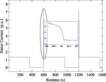
Stator current under 1.3 times rated load and the duty cycle of 60%.
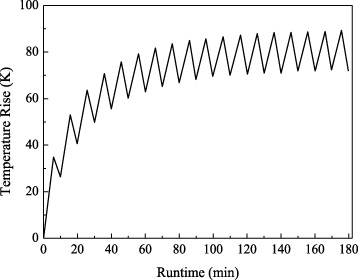
Temperature rise in the motor varying with time under 1.3 times load and 60% load duration.
We can see from Fig. 10 that the temperature rise of the stator winding grows rapidly in the first two operating cycles of the prototype motor, whereas its growth rate decreases in the next operating cycles. When the motor runs to the 6th operating cycle, the difference between the increased temperature rise of stator windings under constant load and the decreased one under the condition of stopping the motor gradually decreases, and the overall growth of the temperature rise of stator windings tends to be flat. When it comes to the 16th operating cycle, the maximum temperature rise of the stator windings stabilizes at 90 K, which is lower than the temperature rise limit of 91 K. Therefore, the maximum temperature rise of the prototype motor operating under S3 working system is hard to exceed the temperature rise limit when the driving load is less than 1.3 times rated load.
Similarly, the temperature rises of the motor operating under 1.4, 1.5, 1.6, 1.7 and 1.8 times rated load and different duty cycles are studied. Figure 11 shows the relationship between maximum temperature rise of stator winding and runtime under different duty cycles when the 1.4 times rated load is driven by the prototype motor.
From Fig. 11, it can be seen that, when the prototype motor operates under 1.4 times rated load and S3 working system, the maximum steady-state temperature rise of the motor is 28, 46, 71 and 101 K for the duty cycle of 15%, 25%, 40% and 60%, respectively. Moreover, the maximum temperature rise of the motor under the duty cycle of 60% is higher than the limit value of temperature rise.
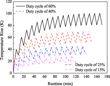
Temperature rise in the motor varying with time under 1.4 times load.
Temperature rise and runtime of the motor under different loads and duty cycles
In the same way, the temperature rise of the prototype motor operating under 1.5, 1.6, 1.7 and 1.8 times rated loads as well as S3 working system with different duty cycles. When different loads are driven by the prototype motor, the maximum temperature rise of the stator windings and the corresponding runtime are shown in Table 2. We can see that, for the same duty cycle, the temperature rise of the motor running to the stable state varies with different loads. In addition, when the motor drives a larger load, the steady-state temperature rise may even exceed the permissible limit of temperature rise. By the proposed method in this work, the relationship between the highest motor temperature rise and the output power as shown in Fig. 12 is obtained when the prototype motor operates under S3 working system. Accordingly, the reasonable rated capacity of the motor running under S3 working system, which prevent the presence of high temperature rise caused by heavy load when the S1-working-system motor operates under the S3 working system.
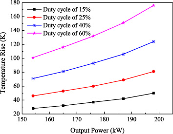
Relationship between temperature rise and output power.
Figure 12 shows that, for the same duty cycle, the temperature rise of the stator winding increases with the increasing output power. For the duty cycle of 60%, the maximum temperature rise of the stator windings keeps greater than the limit value of 91 K all the time. Thus, when the S1 motor runs under S3 working system with the duty cycle of 60%, the output power of the motor cannot exceed 1.3 times rated load, i.e. 143 kW. For the duty cycle of 40%, the temperature rise of the stator winding is higher than the limit value of 91 K when the output power exceeds 174 kW. In comparison, for the duty cycle of 25% and 15%, the motor can start normally, and the temperature rise of the stator winding fails to reach the permissible limit of 91 K. Therefore, if the starting capacity is guaranteed, the S1 motor can safely operate under S3 working system when the duty cycle is 25% and 15%, respectively.
Three-phase induction motor has large heat capacity and is allowed to run under short-time overload. When the motor has high cost or it is difficult to replace the motor, the safe and efficient operation of a motor under different working systems can greatly cut the production cost. However, it is actually difficult to determine the rated power of a motor under different working conditions. This paper focuses on the temperature rise of a cage induction motor with S1 working system operating under S2 and S3 working system, respectively. The transient magnetic-thermal coupling method resolves the difficulty in the calculation of transient temperature rise. Several important conclusions are drawn as below.
(1) A combination of dynamic mathematical model and three-dimensional physical field model for motor is used to evaluate the starting characteristics, loss characteristics and transient temperature rise of motor under different load conditions. This avoids the time-consuming problem when the transient temperature rise is calculated by the strong multi-physics coupling calculation method. The correctness of the proposed model and calculation method is verified by the temperature rise experiment of motor under rated load.
(2) The influence of the starting current on the transient temperature rise of the motor cannot be ignored, especially for medium and large motors with large inertia. The proposed method takes into account the influence of the transient current on the temperature rise of the motor and can improve the accuracy of the calculation of the transient temperature rise.
(3) The influences of load mode on the electromagnetic and temperature rise characteristics are studied, and this research is helpful to guide the determination of rated power of motor under different working systems. In addition, it can be used to decide the starting performance, overload capacity and margin of temperature rise. It not only realizes the reasonable coordination between the driven motor and multi-working load, but also improves the utilization rate of motor.
(4) The rated output powers of the prototype motor are 165, 137, 121 and 115 kW, respectively, under the standard short-time working systems of 15, 30, 60 and 90 min. The maximum temperature rise satisfies the requirement of temperature margin when the prototype motor runs under S3 working system with the duty cycle of 15% and 25%, respectively. The maximum output power of the motor under the duty cycle of 40% and 60% are 174 kW and 143 kW, respectively.
Footnotes
Acknowledgements
The project is supported by the University Nursing Program for Young Scholars with Creative Talents in Heilongjiang Province (UNPYSCT-2018215).