
Abstract
Various technologies have ever been developed to minimize the detent force of linear motors. Although the traditional modular structure can effectively reduce the detent force, the width of the flux barrier and the number of units severely limit its application. To solve these, this paper proposes a new modular type of tubular permanent magnet synchronous linear motor (TPMSLM), which consists of two identical unit motors. For simplification, a subdomain analytical method of the unit motor is firstly established, and its accuracy is verified by a comparison with that of the finite element method. Using the two approaches, the important parameters of the motor are analyzed. A modified two-unit modular TPMSLM is also proposed through the star vectograms of the electromotive force, which achieves thrust performance similar to the traditional three-unit modular TPMSLM with a smaller axial size. Moreover, to make full use of the volume of the flux barrier, end teeth are added at both ends of the unit motors. The simulation results indicate that a reasonable end tooth structure can not only reduce the magnetic leakage phenomenon of the end but also effectively improve the thrust of the motor.
Introduction
Due to the advantages of no transverse end effect, easy control, and high winding utilization rate, the tubular linear motor is widely used in industrial automation and other aspects [1–4], like needle-less injection devices [5] and active vehicle suspension [6]. The linear motor can be generally divided into the induction type and the permanent magnet type. The permanent magnet motor has shorter response time, higher thrust density, less heat, and higher running accuracy. Especially in recent years, the rapid development of permanent magnet material technology has also greatly reduced the manufacturing costs of permanent magnet motors [7].
Despite the aforementioned advantages, the tubular permanent magnet synchronous linear motor (TPMSLM) has certain deficiencies. Its large thrust ripple causes speed fluctuation, vibration, noise, and even resonance. Especially in low-speed operations, this seriously affects the positioning accuracy and servo performance [8]. At present, the main measure to suppress the thrust ripple of TPMSLM is by reducing the detent force. Detent force is mainly divided into the cogging force and the end cogging force [9]. For the cogging force, it can be minimized using the method of skewing poles or slots and pole slot matching [10,11]. The cause of the end cogging force is the discontinuity of the primary core. Presently, the methods to reduce the end cogging force are primarily divided into three categories. The first is to modify the internal structure of the motor, such as optimizing the length of the primary core and improving the shape of the end teeth [12,13]. This method has an obvious effect, but with strict requirements for the processing of the motor. The second is to generate the opposite thrust by setting the compensation current, thereby reducing the detent force [14]. Although this method can completely offset the detent force of the motor, the increase in the compensation current is bound to affect the current density of the motor input, consequently reducing the main thrust of the motor. The last type is to adopt the mechanism of the modular motor. In the working process of modular motor, the detent forces of the unit motors neutralize each other through the position offset between the unit motors, and ultimately the overall detent force reduction is achieved [15–18]. This method does not have strict requirements on the structure design or machining accuracy of the motor, therefore promising a broader application prospect.
At present, many scholars have carried out researches on modular motors. Xi et al. [15] applied the modular structure to the design of linear motors for the first time, he proposed three types of modular linear motors and verified the superiority of the structure through simulation. Gao et al. [16] applied the modular structure to the flat linear motor, thus the width of the flux barrier between the unit motors was deduced theoretically, which resulted in the elimination of the detent force. Huang et al. [17] introduced the modular motor structure into the design of TPMSLM and studied the detent force at different lengths of flux barrier and with different arrangement of windings, however, the modular motor used unit motors of different lengths, which increased the costs of manufacturing. Moreover, the aforementioned modular motor was composed of three unit motors, such a scheme reduced the thrust density of the motor as the flux barrier occupied a certain part of the volume of the motor.
To solve the deficiencies above, this paper improves a modular TPMSLM, which consists of two identical unit motors, separated by a flux barrier. In Section 2, the correctness of the subdomain analytical method (SAM) is verified by the finite element method (FEM). Then, the structural parameters of the TPMSLM are analyzed using the verified model. In Section 3, a two-unit modular motor is built with the obtained optimal TPMSLM parameters. The arrangement of its windings is further improved so that its three-phase windings can be symmetrical in space like the three-unit modular TPMSLM. Finally, under the premise of limiting the thrust ripple of the motor, the sizes of the end teeth and the flux barrier are designed to compensate for the influence of the flux barrier on the thrust.
Thrust characteristics of TPMSLM
Subdomain model of TPMSLM
The improved modular motor is composed of two unit motors, and the parameters of each unit motor are consistent except for the different positions of three-phase winding. Therefore, for modular motors, it is necessary to master the thrust characteristics of the unit motor.
The electromagnetic field calculation problem can be solved by the analytical method and FEM. The analytical method provides a direct physical relationship between thrust characteristics and parameters [19–21]. However, analytic expressions are often difficult to derive, and their applications are severely restricted. FEM is suitable for TPMSLM of various structures, but depending on the size of the finite element model, it will be very time-consuming. Given the characteristics of the above two methods, different methods are used to analyze the unit motor and the modular motor.
The unit motor is suitable for the analytical method due to its simple structure. To reduce the difficulty of the theoretical solution, the unit motor is simplified as a two-dimensional symmetric problem. We make the following assumptions: (1) the shaft and permanent magnet (PM) are isotropic, and their magnetic permeability is equal to that of a vacuum; (2) the permeability of the primary core is infinite; (3) the magnetic circuit can be regarded as unsaturated because the equivalent air gap of the model is large; and (4) the electromagnetic field is distributed periodically along the Z-axis, in that, the end effect is ignored.
Based on the above assumptions, the static analysis model of TPMSLM is, as shown in Fig. 1, established by using the subdomain technology. The h d , h pm, δ, h w , h c , L m , τ are the radius of the shaft, the height of the PM, the size of the air gap, the height of the coil, the thickness of the primary core, the length of the PM, and the pole pitch, respectively. Meanwhile, the TPMSLM is divided into five regions.
Region I: shaft. The conductivity σ is 0.
Region II: PMs. The conductivity σ is 0.
Region III: air gap. The conductivity σ is 0.
Region IV: windings. The conductivity σ is 0.
Region V: primary core. To reduce the eddy current effect, silicon steel sheet material is used, the conductivity is 0.
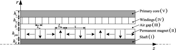
Schematic of the subdomain model.
The magnetic field intensity
The experiment pointed out that for isotropic non-ferromagnetic media,
Therefore, for the pre-magnetized PM, its magnetization characteristics satisfy
Let μ
r
= 1 + 𝜒
m
, we can get
Figure 2 demonstrates the distribution of residual magnetization.
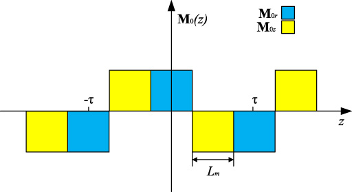
Residual magnetization distribution.
The distribution of residual magnetization can be expressed by the Fourier series as
The Fourier Coefficients
By solving Maxwell’s equations and
The magnetic vector potential
Taking the magnetic vector potential
All electromagnetic quantities are assumed to have a period of 2τ. So the magnetic vector potential
Substituting (13) into (11) and (12), the ordinary differential equations of the subdomains I, II, III, and IV can be obtained as
Solve the above equations using the method of separating variables. The general solution of the magnetic vector potential of each subdomain can be obtained which is
According to the flux continuity law and the ampere loop theorem, the normal component of flux density
The analytical expression of the flux density in the subdomain III are
The electromagnetic thrust of the motor can be written as
Assuming that each armature winding consists of several coils whose radial radius ranges from R
a
to R
c
(R
a
= h
d
+ h
pm
+ δ, R
c
= h
d
+ h
pm
+ δ + h
w
), axial ranges from z − L
w
/2 to z + L
w
/2. According to (23), the thrust F
e
applied to the coils can be obtained by integrating the following formula.
The current density of the three-phase winding is
Finally, the total thrust F
e _total
of the motor can be written as
To verify the correctness of SAM, a finite element model is established using the Maxwell software. The model parameters are shown in Table 1.
Motor structure parameters
Motor structure parameters
In the finite element model as demonstrated in Fig. 3, the mesh at the air gap has been encrypted to improve the calculation accuracy of the finite element. Figure 4 and Fig. 5 indicate the flux density obtained at different positions of the slot-less TPMSLM. The comparison exhibits that the flux density waveform obtained by the SAM is in good agreement with the FEM waveform. However, the flux density of the end obtained by the SAM is slightly larger than that of the FEM since the end effect is not considered in SAM. In addition, with the increase of the radial distance from the permanent magnet surface, the distortion rate of the flux density waveform decreases, and the waveform becomes more and more sinusoidal.
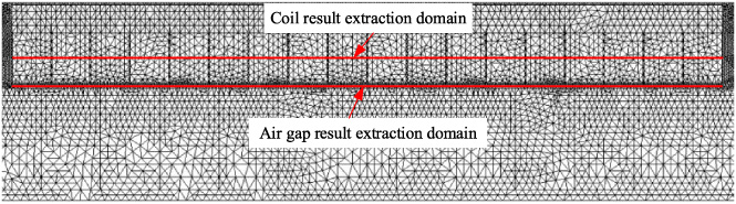
2-D finite element model.
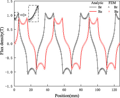
Flux density in the middle of the air gap.
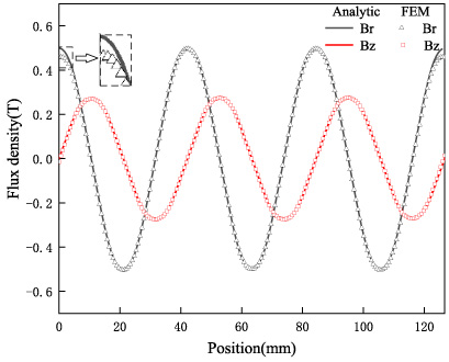
Flux density in the middle of the coil.
Figure 6 compares two types of thrusts solved by the SAM and the FEM. Figure 6(a) shows that when the motor is running stably, the thrust period of SAM and FEM are τ/3 and τ and the average thrusts are 273.57 N and 271.21N, respectively. However, the thrust ripple of SAM is significantly lower than that of FEM because the end effect of SAM is not considered. To further study the accuracy of SAM, Fig. 6(b) compares the relationship between thrust and moving position of SAM and FEM when the A-phase is excited with current excitation (J a = 5 A/mm2).
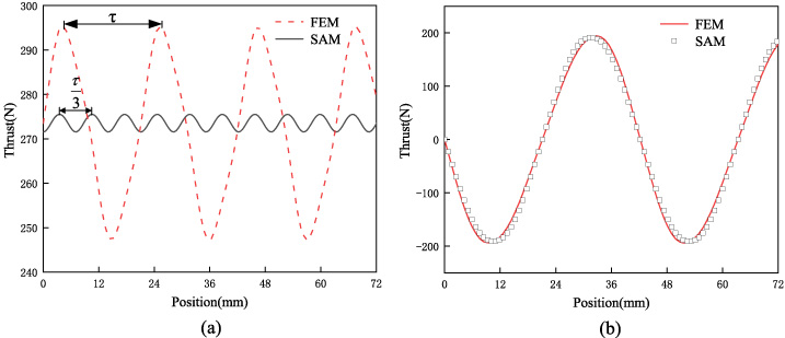
Motor thrust: (a) Steady state thrust. (b) Variation of thrust with mover position at J a = 5 A/mm2.
Under same armature current conditions, the thrust of motors with different percentages of radial magnetization (width of radial PMs/pole pitch) and air gap sizes are calculated by the SAM and the FEM. As can be seen from the results in Table 2 and Table 3, the error of SAM adopted in this paper to solve motor thrust is basically within 1%, and the solution time is only tens of seconds, which significantly reduces the calculation scale and shortens the solving time.
The thrust with different widths of radial magnetized PMs
The thrust with different air gap sizes
Compared with FEM, the advantages of SAM lie in its high computational efficiency and being able to obtain the explicit expression between thrust and motor parameters, but it is more difficult to apply to solving complex structures. To increase the thrust of the motor as much as possible under the limited size, this paper analyzes the size of the PMs and the thickness of the primary core by SAM and FEM.
As can be seen from Fig. 7, with the increase of the thickness of PMs, the air gap flux density amplitude and thrust of the motor indicate an increasing trend. At the same time, the slope of the curve gradually decreases, the thrust and flux density amplitude increase insignificantly, and the utilization rate of PMs decreases. For this reason, considering both the material of the PMs and the thrust of the motor, the thickness of the PMs is selected as 18 mm in this paper.
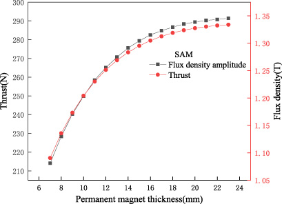
The curve of thrust and flux density amplitude with the thickness of PMs.
The motor adopts Halbach magnetization, and the change of the percentages of radial magnetization does not affect the amount of PMs and the quality of the stator. Therefore, optimizing the percentages of radial magnetization can significantly increase the magnetic load (the amplitude of the equivalent fundamental wave of the air gap flux density) of the motor.
The characteristics of no-load flux density and no-load EMF waveform are used as the criteria for evaluating motor performance. As shown in Fig. 8 and Fig. 9, with the increase of the percentages of radial magnetization, the magnetic load first increases and then decreases, and reaches the maximum value when the percentage of radial magnetization is 0.44. The distortion rate of EMF and flux density decreases first and then increases, reaching the minimum when the radial magnetization ratio is 0.5. When the percentages of radial magnetization account for 0.44 and 0.5, the EMF and the flux density range change from 26.65 V, 1.218 T to 26.49 V, 1.211 T, respectively. The fluctuation range is slight. However, the distortion rate of the EMF and the flux density change from 2.27%, 20.28% to 0.81%, 19.63%, respectively. There are obvious changes, and the excessively high distortion rate causes the ripple of the motor thrust. Therefore, the radially magnetized PMs and the axially magnetized PMs have the best synergy effect when the percentage of radial magnetization is set to 0.5.
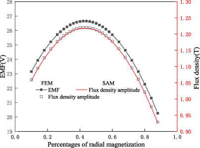
The curve of the fundamental wave amplitude of EMF and flux density with the percentages of radial magnetization.
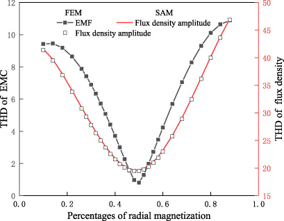
The curve of THD with the percentages of radial magnetization.
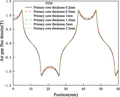
Primary core thickness affects the size of the air gap flux density. It can be seen from Fig. 10 that the air gap flux density increases with the increase of the primary core thickness. With the further increase of the thickness of the primary core, the increasing rate of the air gap flux density gradually decreases. When the thickness of the primary core exceeds 2 mm, the thickness of the primary core has little effect on the air gap flux density.
Air gap flux density with different primary core thicknesses.
Structure principle
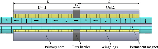
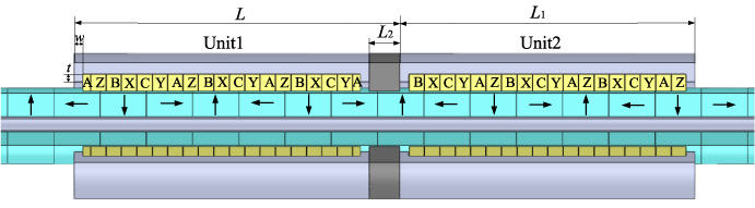
Figure 11 demonstrates a schematic diagram of the improved modular TPMSLM, which is composed of two optimized slot-less TPMSLM in Section 2, separated by a flux barrier. PMs are installed on a non-magnetic shaft and adopt the Halbach array. Compared with other arrangements, the Halbach array can increase the air gap flux density at the working side, and obtain easily the sinusoidal air gap magnetic field.
Improved modular TPMSLM.
The thrust ripple of TPMSLM is mainly caused by the end effect and asymmetrical three-phase winding. The period of the detent force is one pole pitch. Improved modular motors use the position offset between the unit motors to make the detent force between the unit motors have a phase difference of 180°, thereby reducing the basic component of the end detent force [16]. Finally, by changing the position of the three-phase winding to make it symmetrical in space, the thrust of the unit motors is superimposed on each other.
Regarding the improved modular motor in this paper, ignoring the phenomenon of magnetic coupling between the unit motors, the detent force of each unit motor can be described as
Detent force of the modular motor can be expressed as
Therefore, to minimize the detent force of the entire module, the optimal length L of the improved modular motor is
The width of the flux barrier L
2 is
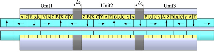
Three-unit modular TPMSLM.
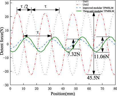
Comparison of detent force of different motors.
Figure 12 is a structural diagram of the three-unit modular TPMSLM. To make a reasonable comparison, the key parameters such as the size of the PMs, the thickness of the primary core, and the current density are kept consistent. According to formula ((31)), this paper selects the flux barrier width L 2 = τ∕2 and L 3 = τ∕3 to establish the finite element model of the improved modular motor and the three-unit modular motor (L 2 and L 3 are the minimum dimensions of the two types of motor flux barriers). It can be seen from Fig. 13 that the improved modular motor reduces the detent force from 45.5 N to 7.32 N through the phase difference of the detent force between the unit motors by 180°. At the same time, due to the tiny flux barrier width of the three-unit modular motor, the magnetic coupling phenomenon is more serious, and the detent force waveform is slightly distorted, making the detent force slightly larger than the improved modular motor.
The length of the primary core of the linear motor is limited, which will cause the space asymmetry of three-phase windings. The traditional modular motor can make the windings symmetrical in space by the cross arrangement of three-phase windings [16]. For the modular motor in this paper, the existing winding arrangement needs to be improved to achieve symmetrical distribution of three-phase windings.
Distribution of the windings
Distribution of the windings
Table 4 indicates two kinds of winding arrangement schemes, in which each unit motor consists of 18 coils. Compared with the unit motor with 6 coils, this type of motor can reduce the influence of the discontinuity of the primary core on the symmetrical distribution of the windings in space.
Star vectograms of EMF: (a) Scheme1. (b) Scheme2.
According to the distribution of the windings in Table 4, the first coil of the motor is taken as the zero phase, and every other coil has a difference of 60° electrical angle. Thus the star vectograms of the motor EMF can be obtained, as shown in Fig. 14. The three-phase EMF vectors of the two schemes are synthesized by multiple vectors and form an angle of 120 degrees in space, which meets the requirements of the symmetrical operation of the motor. However, in Fig. 14(a), the phase vectors synthesized by the two motors differ by 30° from each other. Compared with the phase coincidence of the two motors in Fig. 14(b), the amplitude of each phase of scheme1 will inevitably be reduced.
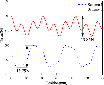
The thrust of two schemes of the winding arrangement.
Figure 15 shows the thrust of the two winding arrangement schemes. The average thrust of the motor in scheme 1 is significantly lower than scheme 2, which is also consistent with the above analysis. In addition, the thrust ripple of scheme 2 is also smaller. Therefore, the improved modular TPMSLM adopts the winding arrangement of scheme two in this paper.
Figure 16 is the EMF and Fourier decomposition diagram of the improved modular TPMSLM and the three-unit modular TPMSLM. It can be seen that the EMF of the two modular motors is roughly symmetrical in space, with a small amount of 5th and 3rd harmonics respectively. In addition, after calculation, the thrust characteristics of the improved modular TPMSLM and the three-unit modular TPMSLM are exhibited in Fig. 17.
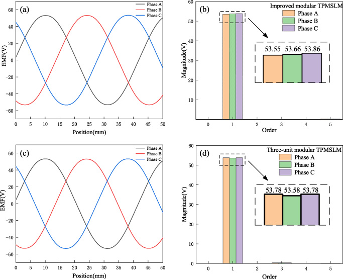
EMF of two types of modular motors: (a)(c) Waveforms, (b)(d) Fourier decomposition column graph.
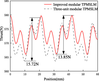
Table 5 summarizes the comparison results of the two modular slot-less TPMSLMs. The results demonstrate that compared with the three-module TPMSLM, the improved modular TPMSLM can not only reduce the processing cost but also achieve the same thrust as the three-unit modular TPMSLM with a smaller axial size. However, after the motor is connected to the power supply, the thrust ripple increases from 7.32 N to 13.85 N, which has significant increase. Therefore, the structure needs to be further improved.
Thrust comparison of two modular slot-less TPMSLMs.
Performance comparison of two modular slot-less TPMSLMs
The modular motor reduces the detent force by introducing the flux barrier. In the meantime, it also reduces the thrust of the motor to a certain extent. According to Eq. (23), when the value of a is determined, the overall length of the motor L is a fixed value. To make full use of the volume of the flux barrier, end teeth are arranged on both sides of the unit motor, which can reduce the magnetic leakage phenomenon and thrust ripple, and also effectively improve the thrust of the motor. The specific structure is shown in Fig. 18.
Improved modular TPMSLM with end teeth.
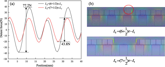
Figure 19 reveals the detent force and flux density distribution curves of the modular motors with teeth when the size of the end teeth is w = 2 mm and t = 6 mm. It can be seen from Fig. 19(a) that the thickness of the flux barrier has a significant impact on the detent force of motors. As the thickness of the flux barrier increases, the detent force of the improved modular TPMSLM with end teeth is reduced from 77.2 N to 43.8 N. The detent force of motors has been significantly improved.
Thrust and magnetic field distribution of two types of geared modular motors.
The above phenomenon is mainly caused by the magnetic field interference between the end teeth of the adjacent unit motor. As can be seen from Fig. 19(b), when the thickness of the flux barrier of the improved modular TPMSLM with end teeth is L 2 = (6 +1∕2)τ − L 1, the magnetic fields of the adjacent end teeth are coupled, resulting in that the detent force cannot be completely offset. When the thickness of the flux barrier is L 2 = (7 +1∕2)τ − L 1, the magnetic coupling between the adjacent teeth is almost eliminated, and the detent force is greatly reduced. Therefore, for the modular motor with end teeth of Halbach array, it can be concluded that the magnetic coupling phenomenon of end teeth can be ignored when the flux barrier width is greater than one pole distance. In addition, it can be seen from the figure that the addition of end teeth can reduce the magnetic flux leakage at the end of the linear motor.
Thrust ripple variation with the end tooth width.
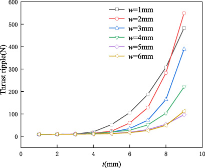
After the end teeth are added into the improved modular TPMSLM, the thrust ripple of the motor increases significantly. Therefore, it is necessary to analyze the width w and height t of the end teeth. Figure 20 manifests the variation curve of the motor thrust ripple with the end tooth size. When t is less than 3 mm, the thrust ripple of the motor has little relation with the size of the end teeth, but when t is greater than 3 mm, it increases exponentially. In Fig. 21, when w is greater than 3 mm, the thrust of the motor is mainly related to the end tooth height. Combined with the above analysis, when t is 3 mm and w is 4 mm, the thrust ripple is the smallest.
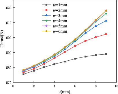
Thrust variation with the end tooth width.
When tooth width w = 4 mm and tooth height t = 3 mm, the thrust waveform of the improved modular TPMSLM under rated load is shown in Fig. 22. The thrust of the modular motor is obtained by superimposing the thrust of the unit motors so that its thrust ripple rate is only 1.69%. Finally, the comparison results of the two improved modular TPMSLM are summarized in Table 6. Hence, the superiority of the improved modular TPMSLM with end teeth structure can be seen.
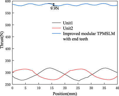
Thrust of improved modular TPMSLM with end teeth.
Thrust performance of two types of improved modular TPMSLM
To overcome the disadvantages of complex processing and flux barrier’s large space occupation for traditional modular TPMSLM, a new modular TPMSLM with a low thrust ripple is proposed, which consists of two identical unit motors and one flux barrier.
The unit motor thrust is derived by solving the boundary value problem, and the accuracy of the calculation result is verified by comparing it with the FEM. Then, the structural parameters of PMs and the primary core are analyzed using the verified model, so that the unit motor can obtain better thrust performance at the limited size. Moreover, a modified two-unit modular TPMSLM is established through the star vectograms of the EMF, which achieves thrust performance similar to the traditional three-unit modular TPMSLM with a smaller axial size. To make full use of the modular space and further reduce the detent force, the end tooth structure is set on the primary core of each unit. The selection method of the end tooth and flux barrier parameters is deduced. The result indicates that the thrust ripple decreases from 2.42% to 1.69%, and the thrust increases from 572.3 N to 584.7 N.
Footnotes
Acknowledgements
This research was financially supported by the “National Natural Science Foundation of China” [Grant No. 52105106], the “China National Postdoctoral Program for Innovative Talents” [Grant No. BX2021126], the “Jiangsu Province Natural Science Foundation” [Grant No. BK20210342], the “Jiangsu Planned Projects for Postdoctoral Research Funds” [Grants Nos. 2021K008A and 2020Z179], the “Nanjing Municipal Human Resources and Social Security Bureau” [Grant No. MCA21121], and the “China Postdoctoral Science Foundation” [Grant No. 2020M671494].