
Abstract
The purpose of this study is to explore the causes leading to the rail gouging from the perspective of armature dynamics. The axial, lateral motion and rotation equations were derived, and a set of calculations according to the experimental conditions were conducted. The calculated in-bore processes of the armature exhibit apparent non-linear features. Especially with the contact interface of armature being worn rapidly, the armature gradually leans toward one side of the bore, and forms a trend of oblique impact to the rail that may lead to the gouging. This study offered an insight on the transient processes of armature in bore, and helped to better understand the gouging failure mechanism.
Introduction
Rail gouging is a severe surface damage that degrades the launching performance and shorten the rail life of an electromagnetic railgun [1]. Gouging can also occur in other high-speed devices, such as rocket sled tracks and two-stage light-gas gun barrels [2]. Present knowledge about gouging was provided by empirical relationships from experiments and numerical results of hydro-codes. A lot of experiments showed that the onset of gouging is primarily a function of sliding velocity for a given material pair [3]. Because gouge craters are characteristically tear-drop shaped with the pointed end facing upstream [4–7], it is believed that gouging is the result of a sliding instability initiated at the microscopic level, which creates a high-pressure interaction core between the slider and rail materials [8].
At the macro level, there must be some impact events that initiate gouging, which may be the oblique impact, asperity impact, or impact with debris between armature and rail [10]. With the impact-induced model, gouge craters have been successfully simulated by hydro-codes such as CTH [9]. Another accepted view among railgun researchers is that gouging may be initiated by the dynamic responses of rail due to armature movement [11–17]. With the rail modeled as a beam sitting on an elastic foundation and subjected to a traveling magnetic pressure load, a critical velocity can be derived, and it depends on the rail geometry, density, elastic modulus and the stiffness of containment structures. Once the armature approaches the critical velocity, rail resonance may occur, which induce high amplitude transverse deformation in the rail at the instant and location of the armature’s passage, and lead to an impact or separation between armature and rail surface. The rail dynamics model is useful to explain why gouging does not occur until the armature reaches a certain velocity, but it lacks sufficient precision to predict the gouging.
Actually, what initiates gouging is a multi-body dynamics problem that all of the components including the armature, the rail as well as its support and containment structures contribute to the system dynamic response. Unfortunately, previous studies of railgun gouging mainly focused on the rail. As the other aspect of this contact-impact problem, the roles of the armature were underrated.
Although the armature dynamics was researched for many years, attentions were not put on gouging but mainly on the issues including the sliding electrical contact, balloting motion of launch package, armature stability, and so on. Knoth [18] modeled the trailing arm of the armature as a simple spring damper system and investigated the armature dynamic response to rail variations caused by surface imperfections and barrel straightness. Chu [19] computed the axial, normal and yaw displacements, velocities and accelerations of the in-bore launch package including armature. Johnson [20] explored the armature dynamics problem from the perspective of stability, and found that the armature could go into an unstable state of divergence or flutter if the armature and payload are not designed properly. Despite not directly related to gouging, these research provided a valuable insight on the dynamic features of the launch process, and show that the armature in motion plays an active role in the interaction with the rails. In addition, these armature dynamics models exhibited more or less nonlinear features.
It is well known that some nonlinear dynamic systems may have initial sensitivity or parameter sensitivity. The occurrence of gouging in railgun also exhibits these sensitivities. In practice, the occurrence of gouging still can’t be predicted accurately. Although only when the velocity exceeds a threshold value will the gouging occur, whether or not the gouging occurs and where it occurs are uncertain even for launching experiments under the same conditions. Because there are always slight differences in the initial states and parameters for each experiment, we speculate that the random occurrence of gouging may be related to the nonlinear features of the system. Therefore, we studied oblique impact events from the perspective of armature dynamics to further accumulate the knowledge about the gouging.
This paper begins with a brief introduction of a railgun experimental system, followed by a detailed description of the armature dynamics model. In the results and discussion section, the nonlinear dynamic behaviors of armature, the mechanism of oblique impact induced by armature dynamics, as well as the control method of the armature in-bore motion are investigated.
Experimental railgun system
The experimental system consists of a rectangular-bore railgun launcher, solid armature, pulsed power supply, and some measuring instruments. The launcher, whose cross section schematic is shown in Fig. 1(a), has a length of 3 m and a bore size of 25 × 50 mm. The launcher has two 20 × 56 mm oxygen-free copper rails surrounded by G10 fiberglass-epoxy insulators inside a laminated stainless steel containment structure. The low hardness of oxygen-free copper makes the sliding electrical contact between armature and rail easier to leave traces on rail surfaces. The laminated containments are bolted in the vertical direction to supply sufficient strength and stiffness.
Cross section schematic.
Circuit diagram of the launching system.
The cross-sectional dimensions of the C-type armature used in the experiments are shown in Fig. 1(b). The armature is made of aluminum alloy and has a thickness of 23 mm.
The circuit diagram of the system is shown in Fig. 2. The pulsed power supply (PPS) is composed of capacitor banks in parallel connections. It provides precise current waveform for the railgun launcher by setting initial voltage and trigger time for every capacitor bank. Each bank is composed of a capacitor C
k
, switch K
k
, crowbar diode D
k
, and inductor L
k
. The railgun is simplified as a variable-resistance and variable-inductance load, which is expressed as the series connection of the resistance
The circuit can be modeled as:
Circuit parameters
Basic dynamic equations
The dynamic model of the armature during launch is illustrated in Fig. 3. The armature is regarded as a rigid body. The degrees of freedom (DOF) x, y, and θ denote the deflection of the mass center away from the centerline of the guide way, the displacement of the mass center along the centerline, and the rotation angle around the mass center in the xy plane, respectively. The interaction between armature and rail is represented by spring-loaded sliding contacts, where k f and k r are the spring stiffness of the front and rear of the armature. The sliders are constrained to slide in between the two rails. The longitudinal forces D i are assumed to be directly proportional to the lateral forces N i via a friction coefficient μ. The electromagnetic propulsion force on the armature in the y direction is simplified as a concentrated force T acting on the pressure center. Moreover, Fig. 3 shows three geometric parameters, 𝜌 is the distance from the pressure center to the mass center, a is half the length of the contact surface between armature and rail, and ϵ is the deflection of the mass center away from the geometric center of the contact part of the armature with the rails.
Armature dynamics model.
According to Newton’s second law, the kinetic equation in the x direction is written as:
In the xy plane, according to the theorem of momentum moment, the differential equation of armature rotating around the mass center is written as:
Mass properties
The coordinate formulas of the mass center can be expressed as:
The moment of inertia about the mass center is written as:
Schematic diagram.
The propulsion force acting on the armature satisfies the following formula:
The propulsive Lorentz force on armature, as a kind of volumetric force, can be simplified to magnetic pressure acting perpendicularly on the armature surface [21]. The magnitude of magnetic pressure depends on the current density:
In Eq. (8), the symbol μ0 refers to the permeability of vacuum, and j is the linear current density that equals to the electric current i divided by the armature thickness c.
The calculation of pressure center is to add the force system into a special point whose resultant moment is 0, that is:
In the x direction, the resultant force of the magnetic pressure is 0, so x
c
= 0. In the y direction, there is:
In Eq. (11), the symbol R denotes to the radius of the arc BC, the symbols k, b, 𝛼, and 𝛽
B
can be expressed as functions of coordinates:
Lateral force
For the dynamic model in Fig. 3, the individual lateral force at each corner is determined by the stiffness of the spring and the overall deflection of each slider from its non-compressed position. The lateral forces N
i
can be expressed as:
The normal contact force can only be pressure, not tension. In our model, the tension is assumed to be negative and the pressure is positive. Only when the preset interference is large enough can the lateral forces of the four corners be kept positive. However, in the actual launching process, the interference will decrease with the wear of armature, which will cause a corner to lose contact. So, constraint conditions for the lateral forces should be added to avoid negative value, and they are expressed as:
The lateral forces of Eq. (13) are only related to the x-direction motion of armature. They are suitable for the N 1 and N 2 at the front of the armature. However, for the N 3 and N 4 at the rear of the armature, the effect of electromagnetic force should be considered. This is because that the armature arm expands outward under the action of magnetic pressure, whereas the deformation of the armature arm is confined by the rails. The greater the electromagnetic force, the greater will be the contact force. In Fig. 4(b), the armature arm is modeled as a cantilever beam with variable cross section. There is a deflection Δ t at the tailing end of the armature arm when only the magnetic pressure P is applied. We apply a concentrated force N P at the tailing end of the armature arm to balance the magnetic pressure P, so that the deflection Δ t is 0. The force N P can be regarded as a reaction force provided by the rail to resist the deformation of the armature arm.
Only uniformly distributed load P applied, the tailing end of the armature arm generates a deflection which is expresses as [22]:
The tailing end deflection of the armature arm subjected only to a concentrated load N
P
is
The force N
P
, determined by combining Eqs (15) and (17), is a variable depending on the structure of armature arm and the magnitude of electric current. The lateral forces at the rear corners of the armature in Eq. (13) should be revised as follows:
Only when N P is taken into account can the electromagnetic force in the x direction be balanced.
The assumptions used in the friction model include:
(1) The magnitude of sliding friction is directly proportional to the normal load between the contact surfaces.
(2) The friction coefficient is independent of the contact area.
(3) Under extreme load conditions, the friction coefficient decreases with the increase of sliding velocity.
Friction is based on a Coulomb formulation and the friction forces at the four corners of the armature can be expresses as [23]:
The friction coefficient is assumed to decrease exponentially with the velocity of the armature, which can be written as [24]:
Until now any dynamic friction values have not been measured in an electromagnetic launcher. R. Marshall [25] thought the average friction coefficient in the range 0.2 to 0.25, is reasonable for railguns at the test conditions. L. Brown [26] measured the friction coefficient in the presence of high current density and got a rough value about 0.15. Since no experimental friction models exist for a railgun launcher, an approximate friction had to be used. According to the analysis and discussion in [20], the parameters in Eq. (20) are: μ d = 0.05, μ s = 0.25, and 𝜆 = 0.01.
The spring stiffness coefficients k
f
and k
r
in Eqs (13) and (18) can be determined by the model of spring in series. Of all the components including the armature, rails, insulators, and containments, the steel containments which are very thick in size, have the highest stiffness and the least contribution to the total stiffness. So, only the stiffness of the armature, rails, and insulators are taken into account, they are accumulated according to the following equations [27]:
As shown in Fig. 1(a), all of the launcher components have rectangular sections and are under compressive loads, so the k
af
, k
c
and k
s
are compressive stiffness, and can be approximated by the following equation [28]:
The stiffness of the armature’s rear, k
ar
, is a bending stiffness and can be estimated by Eq. (17), that is:
According to the sizes of armature and launcher in our experiments, as well as the material properties given in the literature [13], the stiffness coefficients are calculated and listed in Table 2.
Stiffness coefficients (Unit: N ⋅ m−1)
Table 2 shows that the total stiffness is almost determined by the armature, and the value of k f is much larger than that of k r .
In the armature dynamics model, the calculation of force and moment is directly affected by the interference fit between armature and rail, the wear of armature, and the variation of rail spacing caused by rail vibration.
Interference fit
Interference fit is an effective method to acquire good electrical contact between armature and rail. The interference has been taken into account in Eqs (13) and (19) by the term Δ. It should be designed within a suitable range. Otherwise, excessive interference will greatly increase the drag force acting on the armature, and even will lead to rail surface damage. In our model, different interference values, Δ f and Δ r , are set for the front and rear of the armature, respectively. Furthermore, it is assumed that once the armature starts to move, the interference will no longer work due to the rapid wear of the armature contact surface.
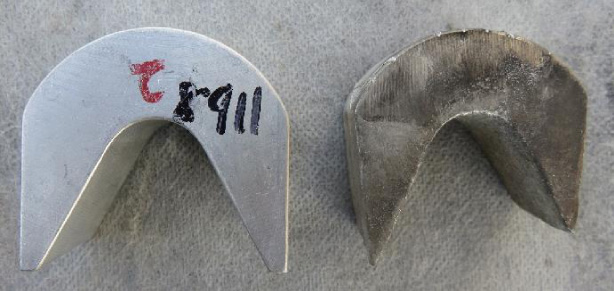
Comparison of the armatures before and after launch.
Subjected to the different contact forces, the front and the rear of the armature experience different wear processes. Figure 5 shows a photograph of armatures before and after launch. It can be seen from the right armature that the rear has been sharpened, which indicates that the wear depth of the rear is larger than that of the front. This phenomenon is related to the fact that the armature arm expands under the action of electromagnetic force, and always keeps high contact pressure with the rails. To compensate the armature wear by the deformation of armature arm is the key point of the electrical contact maintenance mechanism of the C-type armature. However, the wear of the armature front lacks a compensation mechanism, and has a great effect on the lateral motion of the armature. Therefore, the wear of the front needs to be considered in the armature dynamic model.
Due to the velocity skin effect, little electric current flows through the armature’s front. The wear of the front is mainly mechanical wear, and can be described by Archard’s law of wear. The wear volume is calculated by the following formula:
Ideally, the two rails should be parallel to each other, but the actual rail spacing will vary slightly along the barrel axis. In our model, two types of rail spacing variation are considered: one is when the armature reaches the critical velocity, the rail resonance occurs and the rail develops a localized buckle ahead of the armature; the other is to set the rail spacing at the breech slightly larger than that at the muzzle, and the two rails form a tapered bore.
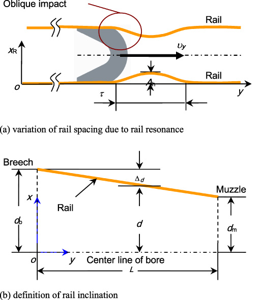
Schematic diagram.
Based on the investigations about the rail resonance, the contact picture of armature and rail is shown in Fig. 6(a). Although the rail buckles when resonance, its deformation will be constrained by the insulator, so the deformation amplitude of the rail will not be too large. The shape of rail hump is assumed as a half-period sinusoidal function with a height of A
h
, a width of τ, and a starting position at y
h
, which is expressed as
Once the armature reaches the critical velocity, the rail spacing ahead of the armature, which is presented in Eq. (4) by the symbol d, is revised by subtracting the term x R . The x R is also regarded as interference fit and included in the calculation of contact force N i . In brief, Eq. (25) can describe the rail that out of straight locally caused by some reasons.
In Fig. 6(b), the inclination of the rail from breech to muzzle is defined as (d
b
− d
m
)∕L, where d
b
and d
m
are half of the rail spacing at the breech and muzzle respectively, and L is the length of the barrel. The rail spacing d and shrinkage Δ
d
toward the barrel center line vary with coordinate y, and satisfy the following equations:
With the equations above, the lateral force in Eqs (13) and (18), as well as the torque in Eq. (4) are revised as follows:
Let
Results and discussion
Experimental phenomena
We carried out a group of launching tests with the same experimental conditions. It was found that the location and shape of the gouging craters are different in each experiment. Some gouging craters are shown in Fig. 7. They occurred halfway or later down the rail, at which time the armature had been accelerated to a very high velocity. Moreover, they have the following features:
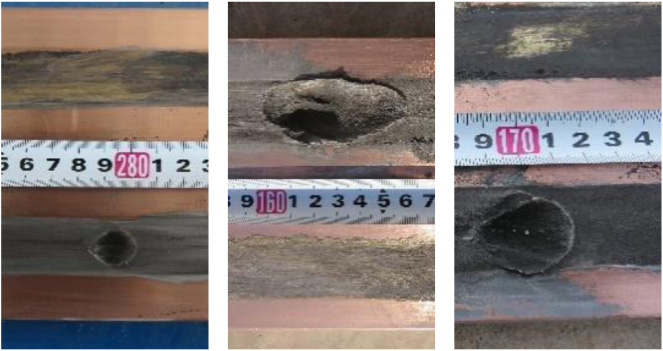
Photographs of gouging crater.
(1) The width of each crater is roughly equal to that of armature, which implied that when the gouging occurred, the armature experienced a strong whole interaction with the rail, rather than a local interaction on its contact surface.
(2) The rail on the gouged side presents gray color due to the aluminum deposition, and the rail on the opposite side presents yellow color of copper after being ablated by arc, which suggests that the armature kept good electrical contact with the gouged side rail, whereas arc transition occurred between the armature and the other rail due to insufficient contact. Briefly speaking, it implies that the armature has leaned toward one side rail before the gouging occurred.
These phenomena suggest that lateral motions of armature, not just deformations of the armature arm, may have happened during the launching processes, and then make high-speed oblique impact of armature on rail possible.
By numerical simulations, we attempted to explain the causes of the lateral motions from the perspective of armature dynamics. Besides those parameters directly given in Sections 2 and 3, the other calculation parameters are listed in Table 3.
Calculation parameters for armature dynamics
Calculation parameters for armature dynamics
Of all the parameters in Table 3, wear coefficient K w is the one that is difficult to be determined. Exact wear data under the conditions of railgun have not yet been found from the existing literatures. What listed in Table 3 is an estimated value that was combined the empirical value of 1 mm per meter [29] with the experiment of Fig. 5.
Before discussing the lateral dynamics of armature, the calculated longitudinal motion of the armature was checked. The Rogowski coils and B-dot probes were used to measure the current and the in-bore motion of the armature. It can be seen from Fig. 8 that the variations of the electric current and armature position with the time are in accordance with the experiment. In Fig. 8, the subscript “e” denotes experiment and the “s” denotes simulation.
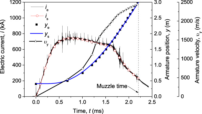
Comparison of calculated current and armature position curves with experiments.
The armature dynamic model is essentially non-linear. The deviation of the initial value and the disturbance in the launching process may cause the armature to experience different dynamic processes. The initial value deviations derive from many aspects, such as the armature manufacturing tolerance, initial skewness and deflection of armature at the starting position. In addition, rail variations caused by surface imperfections, barrel straightness, and rail vibrations may also disturb the dynamic process of armature.
We evaluated the initial sensitivity of armature dynamics model by setting small initial values for different numerical examples. With the sub-models such as the tapered bore and the front wear of armature not considered, the dynamic processes of armature were calculated by presetting the initial displacement in the x direction, the initial rotation angle, or the irregularity of one-sided rail separately. The initial values were set as the following:
No. 01: x 0 = 0 mm, θ0 = 0.1°;
No. 02: x 0 = 0.1 mm, θ0 = 0°;
No. 03: x 0 = 0 mm, θ0 = 0°, but there is a slight bend on one-sided rail, and its shape satisfied Eq. (25), in which y h = 0.5 m, τ = 0.3 m, A h = 0.2 mm.
The numerical examples were numbered in Arabic numerals in order to distinguish them.
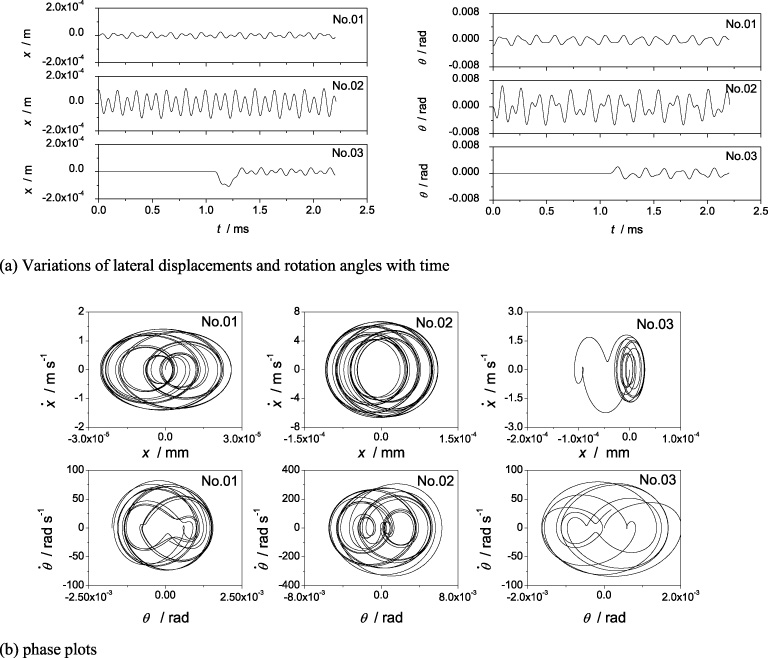
Results of examples No. 01–03.
Figure 9(a) shows the lateral displacement and rotation angle curves of three examples. It can be found that any small initial value caused the lateral and rotation motion of the armature. Moreover, because the vibrations in x and θ are coupled, if vibrations are excited in one of the DOFs, they will also lead to vibrations in the other one. The curves shown in Fig. 9(a) seem to be periodic. But as can be seen clearly from the phase plots of Fig. 9(b), the trajectories of these solutions on the phase plane are not closed curves. They either tend to be concentrated in some closed bands or oscillate between two maxima in a chaotic manner.
With the assumption that the rails are perfect flat and straight, calculations were conducted by considering the armature wear. In examples No. 04–07, initial displacements and rotation angles with the same amplitude but different directions were preset, which the amplitudes are |x 0| = 0.1 mm, |θ0| = 0.1°, and the combinations of initial direction for x and θ are: (+ +), (+ −), (− +), and (− −) respectively.
Figure 10 shows that the mass center and the rotation angle of the armature eventually lean toward one side rail regardless of the positive or negative initial values. One of the features of lateral force is that it will increase when the armature leans to this side, so as to make the armature return to its equilibrium position. As described in Eq. (14), the lateral force can only be positive. Moreover, it can be seen from Eq. (27) that the lateral forces N 1 and N 2 decreases with the growth of the wear depth W f . When W f is very small, it has little effect on N 1 and N 2. Once W f increases to a certain extent, it will be difficult for N 1 or N 2 to obtain a sufficient lateral force to push the armature back to its initial equilibrium position. This may be the reason that the traces in Fig. 10 gradually lean toward one side.
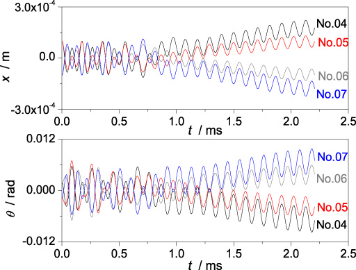
Variations of DOFs with time for examples No. 04–07.
The results in Fig. 10 suggest that the armature will enter the motion mode shown in Fig. 11. This kind of armature motion occurs in the high-velocity stage, which causes the rail on one side to be pressed and impacted, and may lead to severe wear and even be gouged. Moreover, a gap may arise between the armature and the opposite side rail, which leads to the arc transition due to insufficient contact area. This physical picture can be used to explain the experimental phenomena in Fig. 7 that only one rail was gouged, meanwhile, the other was eroded by arc. In addition, different combinations of initial deflection and rotation result in different directions of armature leaning, which means that the slight differences of initial states may affect which rail will be gouged eventually.
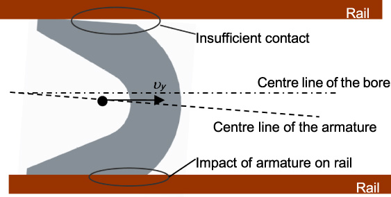
Physical picture of armature leaning toward a rail.
These numerical examples above suggest that the occurrence of gouging may be related to the dynamic behavior of armature under wear.
In a railgun barrel, the rail vibrates under the action of electromagnetic force, and resonance occurs when the armature is accelerated to a critical velocity. The critical velocity can be expressed as [12]:
In order to take account of the rail bending when the armature reaches the critical velocity, the model of Fig. 6a was used for the two rails and the parameters of Eq. (25) were set as follows: y h = 1.48 m, τ = 0.03 m, A h = 1.0 mm. Meanwhile, the wear of the armature front was considered and the initial values for x and θ were set as: x 0 = 0.1 mm, θ0 = 0.1°. This example was labeled as No. 08.
In Fig. 12, the DOFs-time curves of No. 04 and No. 08 are compared. The only difference between their calculation conditions is that the rail resonance is considered in No. 08. It can be seen in Fig. 12 that after the time of critical velocity, the directions of the deflection and rotation are reversed and the amplitudes become higher, which means that disturbed by the rail resonance, the armature leans toward the other side rail and produces stronger impact on it. In this situation, the occurrence of gouging becomes more easily.
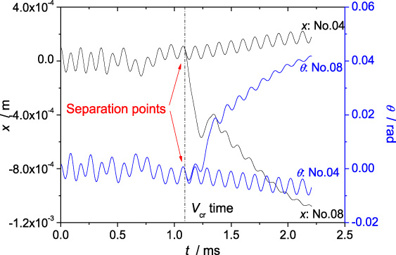
DOFs vs. time curves of numerical examples No. 04 and No. 08.
The example No. 08 also suggests that the gouging may occur at any time after the critical speed. For example, the gouging in Fig. 7 occurred at 2.78 m, 1.60 m, and 1.69 m respectively, which are all after the 1.48 m position of critical velocity.
According to the above analysis, the behavior of high-velocity armature leaning toward a single rail is mainly induced by wear of the armature’s front, therefore, we considered to use the concept of tapered bore to compensate the wear gap. Based on the example No. 04, the armature dynamic processes were calculated by setting the shrinkage of rail spacing at muzzle (Δ d ) as 0.5 mm, 1 mm and 2 mm, respectively, and the corresponding examples were labeled as No.09–11.
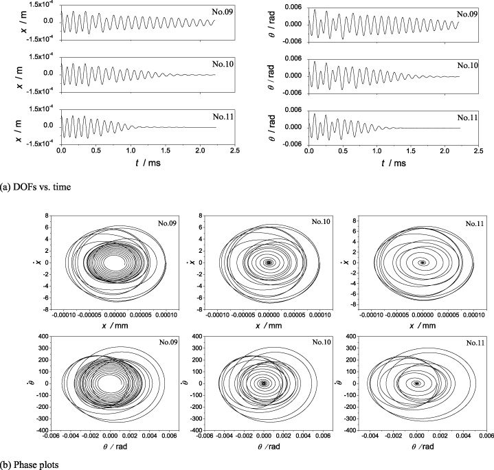
Results of example No. 09–11.
Effects of Δd on muzzle velocity
Figure 13(a) shows that the higher the shrinkage of rail spacing at muzzle is, the faster the oscillations converge. It can also be seen from the phase plots of Fig. 13(b) that the phase trajectories converge inward, especially for No. 10 and No. 11, whose phase trajectories converge to a point. These examples show that the tapered bore can suppress the armature swing and balloting between two rails, and play a positive role in stabilizing the lateral motion of armature. However, the inclination of the rails should be preset within a certain range, otherwise some adverse effects will arise, such as increasing drag force of the armature, decreasing the velocity of the armature, and even wearing the rail seriously. Table 4 lists the variations of muzzle velocity 𝜐 y with Δ d .
Table 4 shows that the muzzle velocity decreases with the increase of Δ d . This is due to the reduction of rail spacing, which increases the normal contact force N i between armature and rail, and then increases the frictional resistance D i . The excessive contact force may also lead to rail surface damage, so the tapered bore should be designed cautiously and considered from as many aspects as possible, such as the armature structure, electric current waveform, and armature wear.
We developed a dynamic model of armature to investigate the mechanisms of rail gouging. Some conclusions are summarized as follows:
(1) The armature experiences a non-linear dynamic process, in which the lateral balloting and rotation of armature occur, and the dynamic response of armature is sensitive to initial values.
(2) The wear of armature’s front leads to the armature leaning toward one side of the bore, forming a situation of tight contact on one side and loose contact on the other side. This behavior can be used to explain the experimental phenomena that rail gouging on one side and arc transition on the other side.
(3) The magnitude of armature leaning toward one side grows rapidly after the critical velocity.
(4) The concept of tapered bore is helpful to compensate the armature wear and stabilize the lateral motion of armature. However, the taper should be designed cautiously.
In our model, some key factors including the armature structure, rail supporting structure, rail irregularity, electric current waveform, friction and wear have been taken into account. Besides the application in the gouging mechanism research, the calculation of motion and contact in bore can also provide reference for armature design. The model is only for the armature at present because the payload at the front of the armature is not considered. The emphasis in future work should be on the development of a dynamic model of integrated launch package for the multi-body system composed of armature and payload.