Mathematical modeling of coupled non-linear electromagnetic, thermal and hardness fields is a sufficient tool supporting designing of various kinds of induction hardening technologies. The paper deals with the modeling of two kinds of the induction hardening of gear wheels made of 41Cr4 steel. Flux 3D for coupled electromagnetic and thermal fields computation and own procedures for hardness distribution were applied. Reasonable accordance between calculations and measurements was achieved.
The surface induction hardening is pointed to hardening of thin zone of the material only and keeping soft its internal part. The paper deals with the modeling of two kinds of such processes: Single Frequency Induction Hardening (SFIH) and Consecutive Dual Frequency Induction Hardening (CDFIH) and their validation. It requires analysis of coupled electromagnetic and temperature fields during induction heating and temperature and hardness fields during cooling. The accuracy depends on material properties, heat transfer parameters and their dependences on temperature, correct data of phase transformations temperatures etc. [1].
Mathematical model
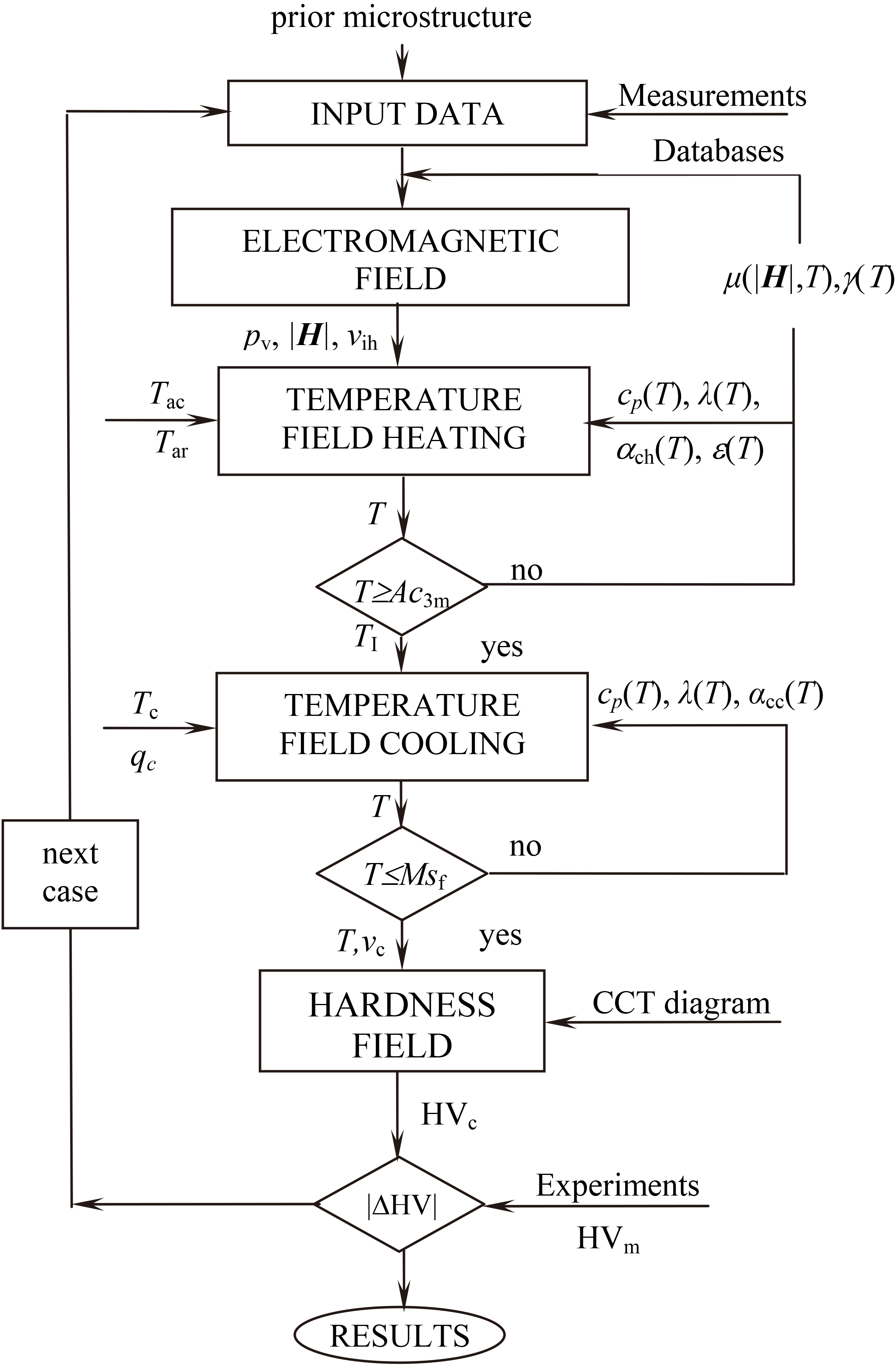
The block diagram of the computational procedure for induction hardening was presented in Fig. 1. Volumetric power density released in the workpiece consists of two components: the hysteresis losses and Joule losses .
Hysteresis losses are dependent on the magnetic strength H and on the frequency, however for the analyzed case they could be neglected [2].
where – induced current density, – electric conductivity.
Block diagram of computational procedure for induction hardening.
The boundary condition for temperature field [3] was considered as:
where – convection heat transfer coefficient for induction heating, – Stefan-Boltzmann constant, – emissivity, , – temperature of convection and radiation environment respectively.
The heating was terminated when the hardening temperature exceeds the modified upper critical temperature Ac.
where – the upper critical temperature for a conventional hardening and – velocity of the induction heating.
The dependence Eq. (5) was determined from the Time Temperature Austenitization (TTA) diagram. This modified critical temperature secures a completion of the austenite transformation. Then the temperature field during cooling was calculated. The temperature dependent heat transfer coefficient during cooling represents convection only. It was determined by measurements. This stage was terminated when the average temperature at the working surface has begun to be smaller than the Ms (Martensite Finish Temperature) secured termination of the martensite transformation [4]. Based upon the calculated velocity of cooling the hardness distribution within the body was determined by the measured Continuous Cooling Transformation (CCT) diagram [5]. At the end the calculated hardness distribution (HV) is compared with the experimental data (HV) and if the inaccuracy tends to the expected small enough value final results were registered. In contrary the next case with a modified input data begins to compute. The numerical solution was provided by the Flux 3D software with some own procedures. An attention was paid to a convergence of results which are dependent on the density of discretization meshes.
Illustrative example
As the example the SFIH and CDFIH processes of gear wheels made of steel 41Cr4 were analyzed. Basic parameters and dimensions of the induction hardening system were as follows:
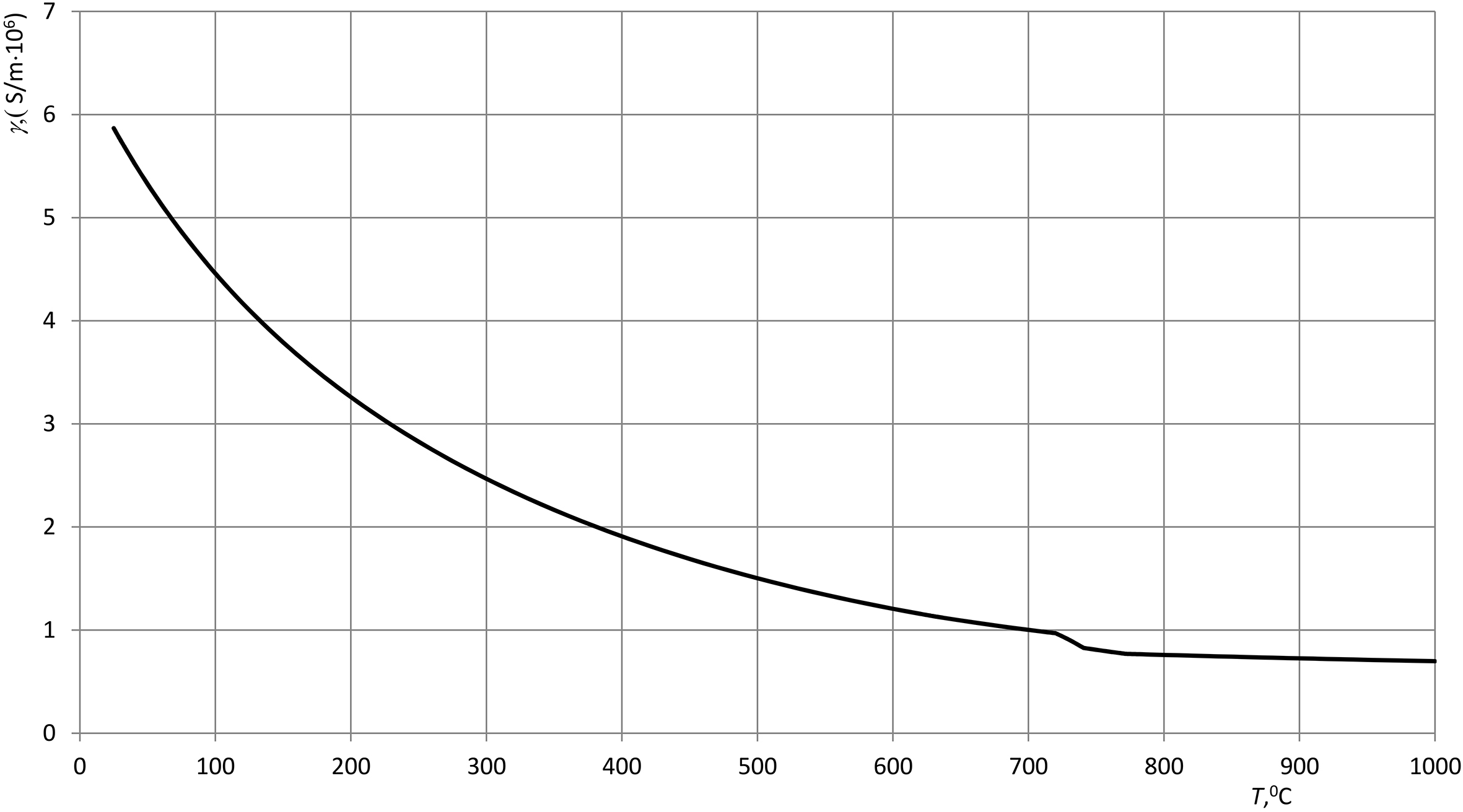
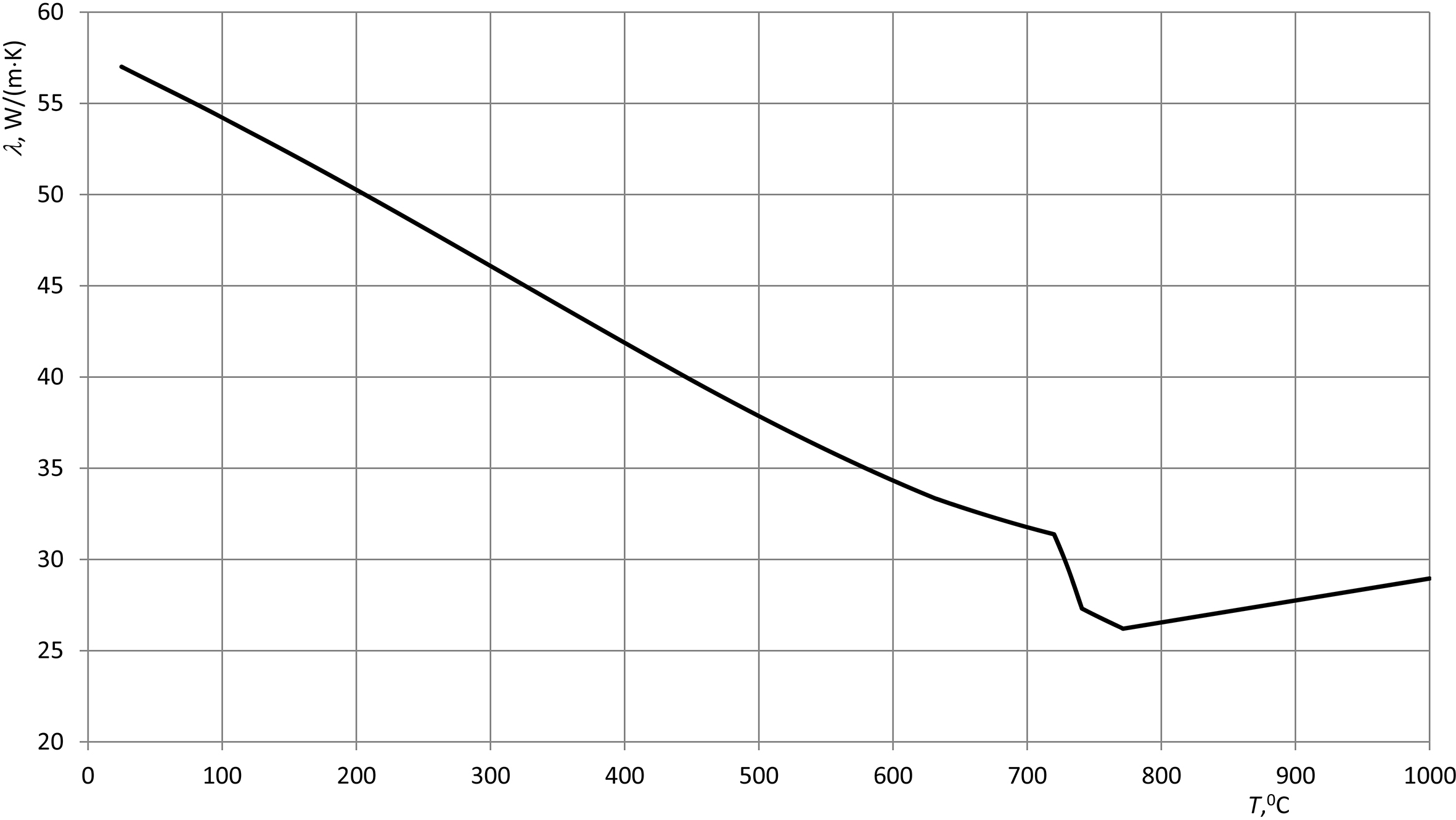
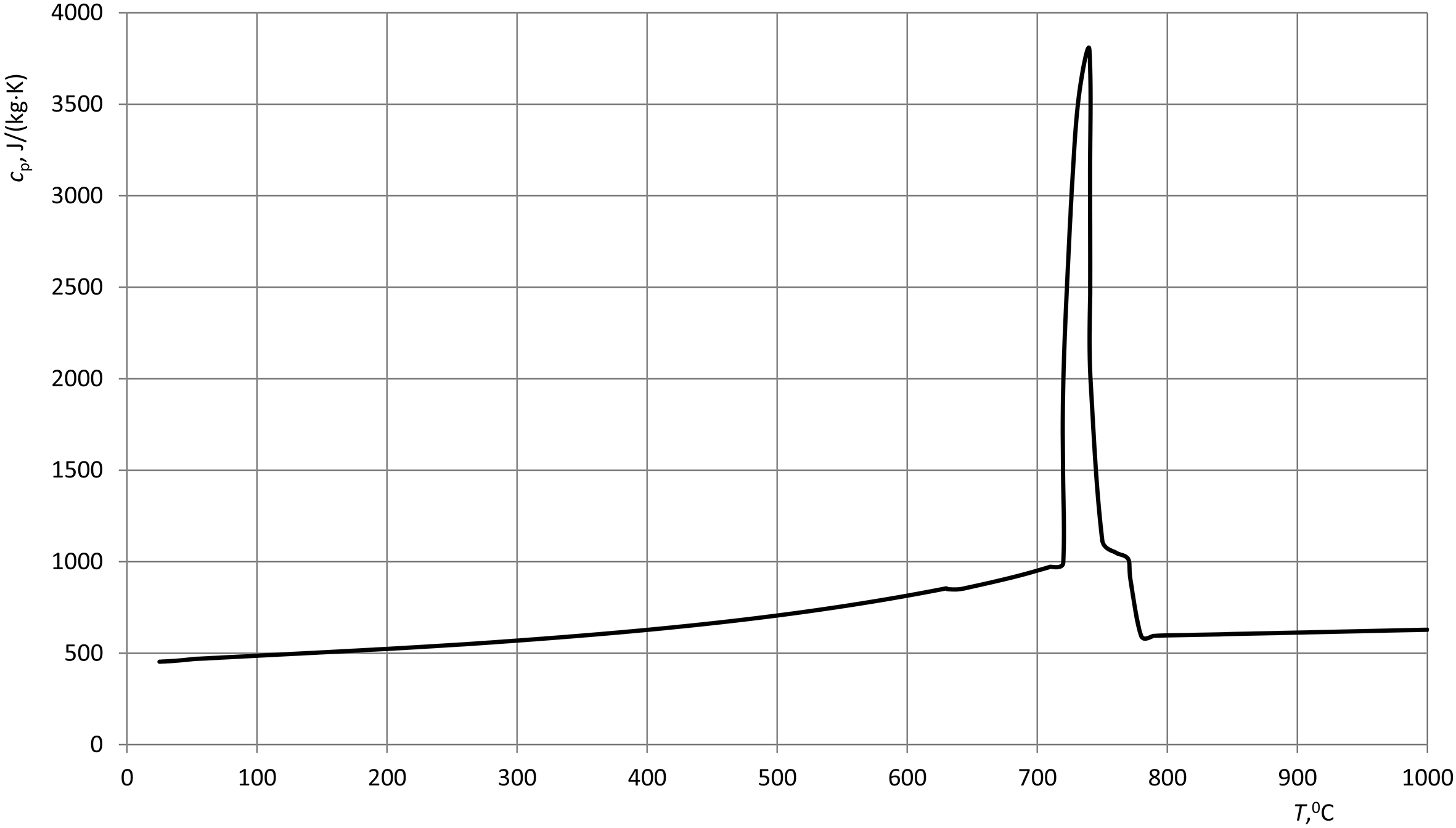
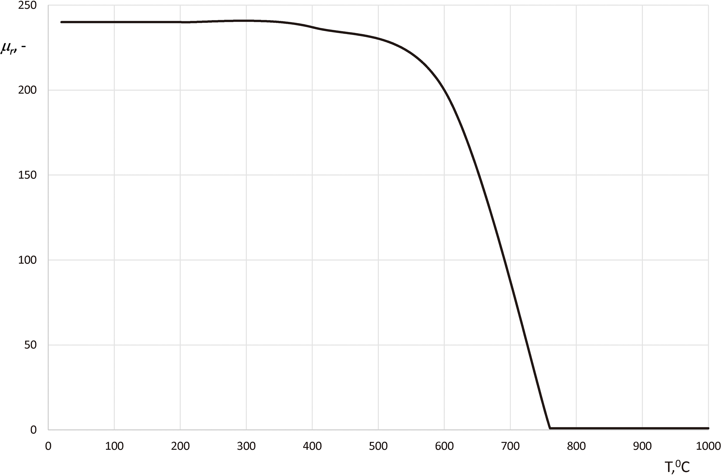
Gear wheel: teeth number 16, width of the tooth ring 0.006 m, external diameter 0.0356 m, internal diameter 0.0269 m, diameter of the hole 0.016 m, chemical composition of the steel in Table 1 and temperature dependent material properties in Figs 2–5 were presented.
Chemical composition of steel 41Cr4
Element
C
Cr
Si
Mn
Ni
Cu
%
0.4
1.05
0.24
0.73
0.16
0.16
Dependence of electric conductivity on temperature.
Dependence of thermal conductivity on temperature.
Dependence of specific heat on temperature.
Dependence of relative magnetic permeability on temperature.
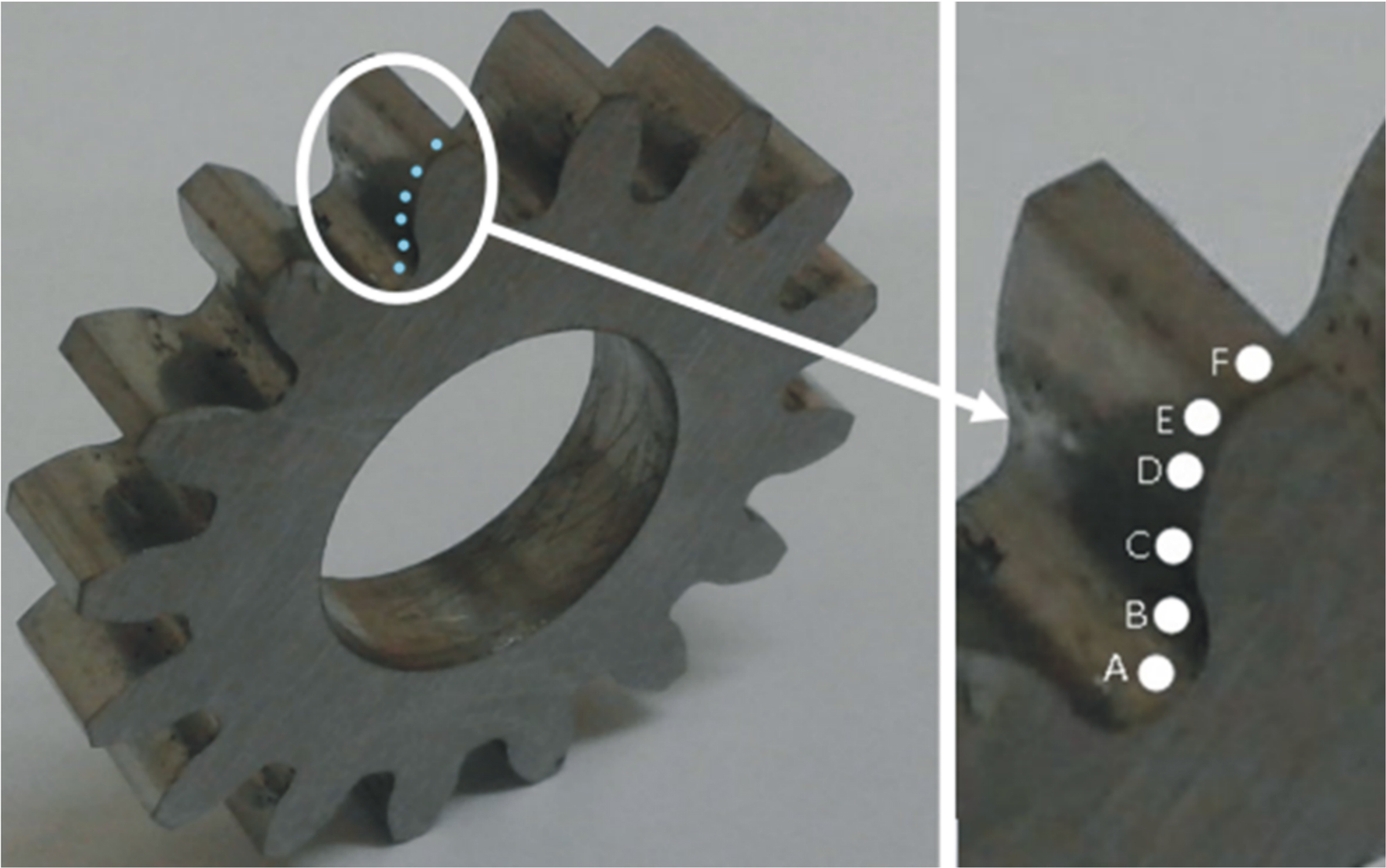
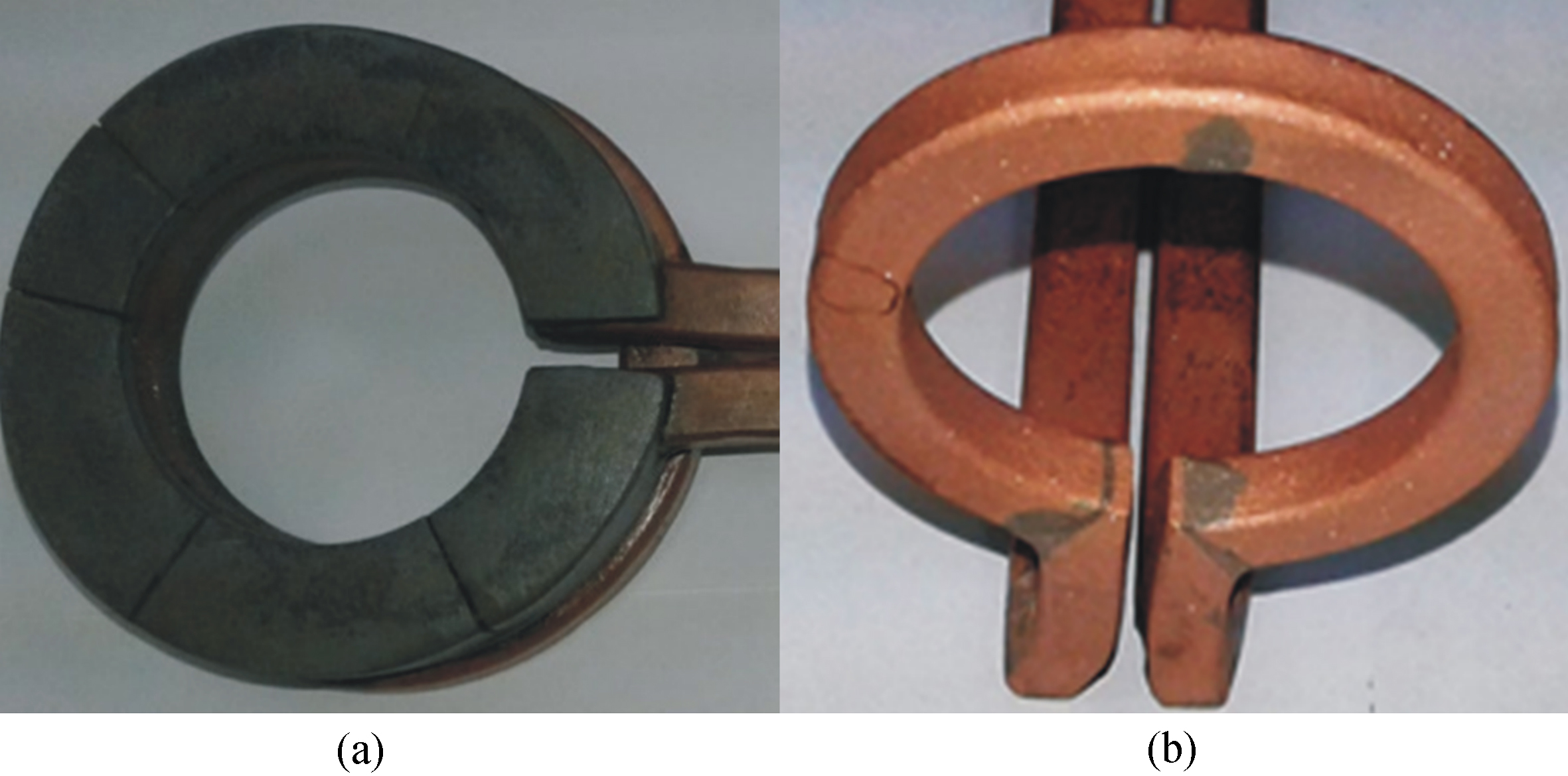
The gear wheel (Fig. 6) with depicted points A-F located along the working surface of the tooth is shown in Fig. 6. It is heated by the high frequency (HF) inductor (Fig. 7a) and then immediately cooled by the sprayer for the SFIH process or by the medium frequency (MF) inductor (Fig. 7b), next by the high frequency (HF) inductor (Fig. 7a) and then immediately cooled for the CDFIH process.
Gear wheel with depicted A–F points along its working surface.
HF inductor-sprayer system (a) and MF inductor (b).
HF inductor: number of coils 1, height of coil 0.007 m, total height 0.021 m, external diameter 0.061 m, internal diameter 0.0395 m.
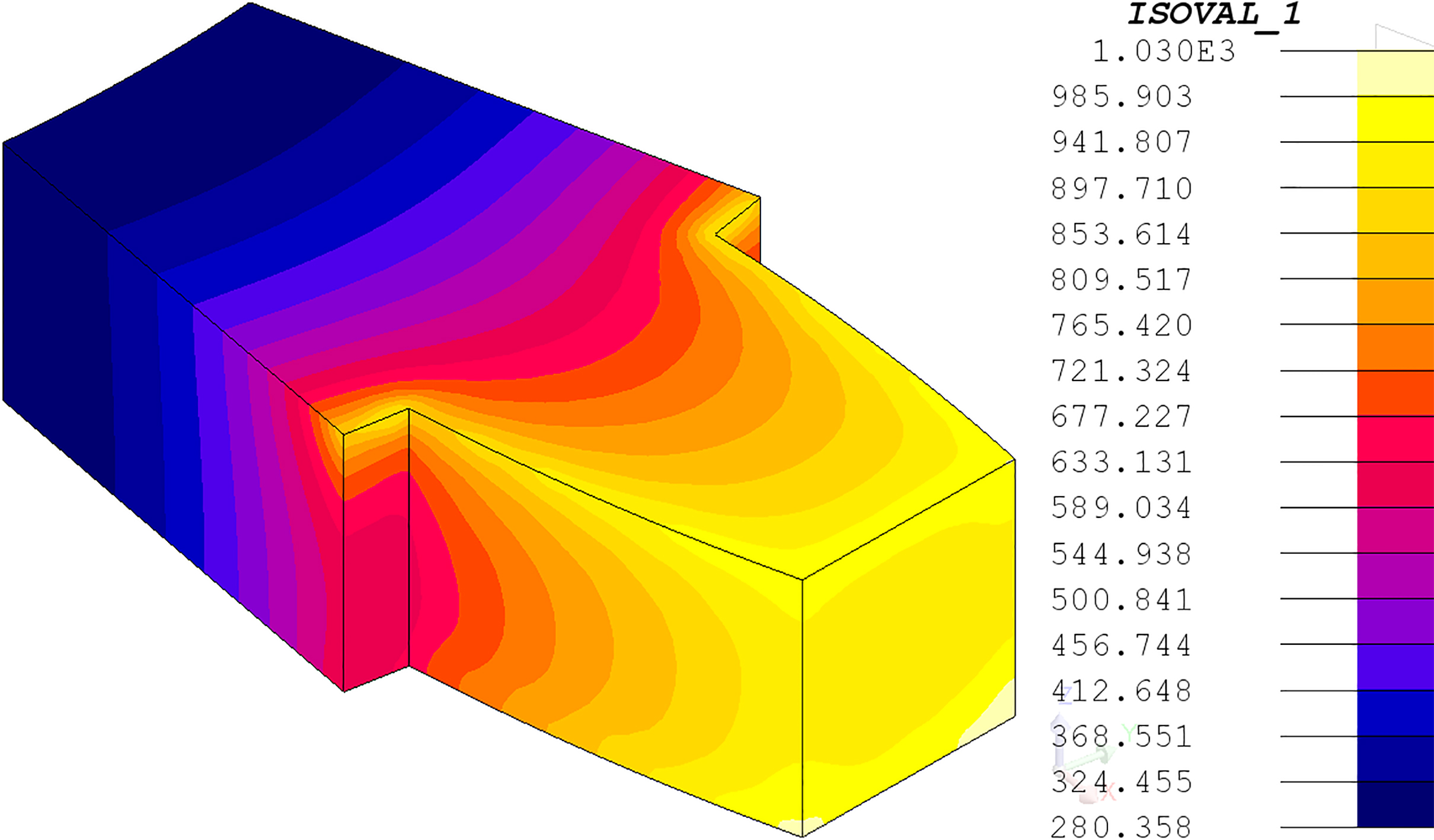
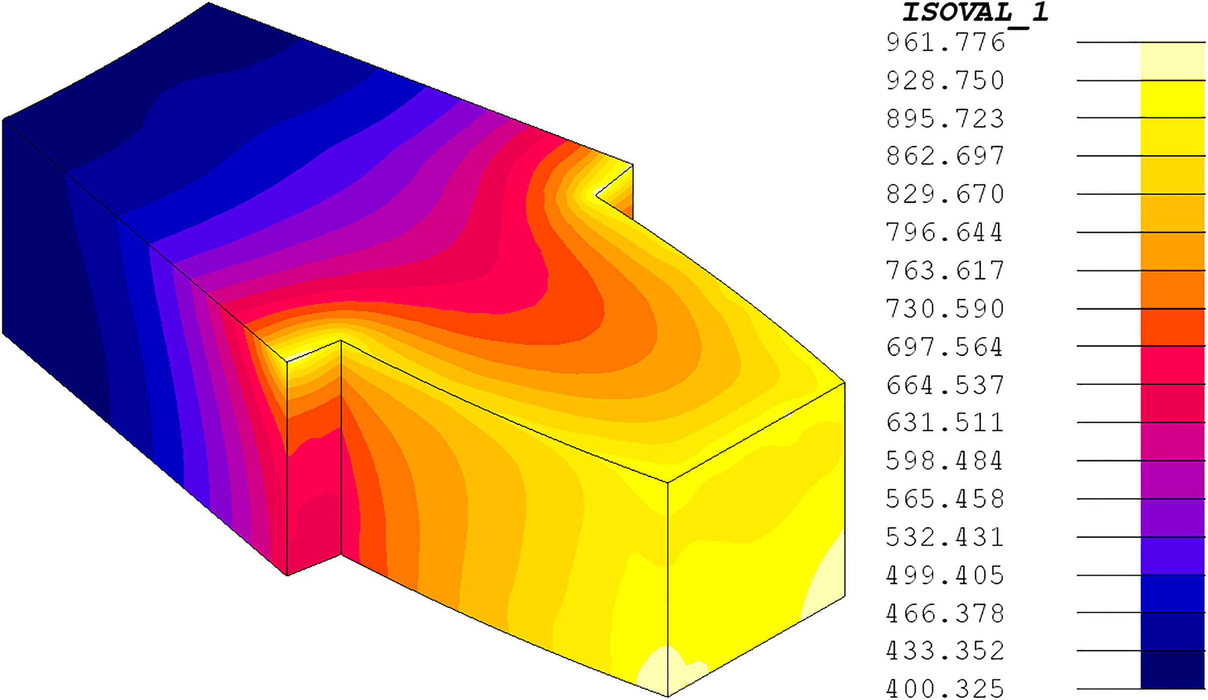
SFIH process. Temperature distribution within the whole tooth after 4 s.
Flux concentrator: Fluxtrol 50, density 6100 kg/m, relative magnetic permeability 36 55, saturation flux density 1.2 T, electric conductivity 2 10 S/m, external diameter 0.082 m, internal diameter 0.039 m, thickness of upper and lower layers 2 0.005 m.
Sprayer: distance between inductor and sprayer 0.02 m, external diameter 0.085 m, internal diameter 0.061 m.
MF inductor: number of coils 1, height 0.007 m, external diameter 0.054 m, internal diameter 0.0395 m, length of bus-bars 0.363 m.
Heat transfer parameters – cooling: quenchant polymer solution Aqua Quench 140, temperature 30C, flow-rate 10 m/s, concentration – 12 %, density 1070 kg/m, kinematic viscosity 1.04 10 m/s, convection heat transfer coefficient 1200 W/(mK).
Parameters of the SFIH process: power of the generator 20 kW, current 500 A, frequency 280 kHz, time of heating 4 s, velocity of heating 230 K/s, upper critical temperature Ac 920C, lower critical temperature Ac 720C, hardening temperature 970C, the time between heating and cooling: 0.1 s, rotation velocity 2 r/s.
Parameters of the CDFIH process: power of the generator: 60 kW, current 1385 A, heating time 4 s, frequency 36 kHz, time between MF and HF heating 0.1 s, temperature 500C, power 20 kW, current intensity 500 A, frequency 280 kHz, time of heating 0.7 s, velocity of heating 210 K/s, upper critical temperature Ac 915C, lower critical temperature Ac 715C, hardening temperature 960C, time between heating and cooling: 0.1 s, rotation velocity 2 r/s.
Numerical models: calculation area for coupled fields – 1/4 part of the whole tooth, number of nodes – 41376, SFIH: time of computations – 900 s, number of iterations – 81, CDFIH: time of computations – 2400 s, number of iterations – 267.
Results
First let us consider the SFIH process. Temperature distribution after heating time 4 s within the whole tooth was shown in Fig. 8.
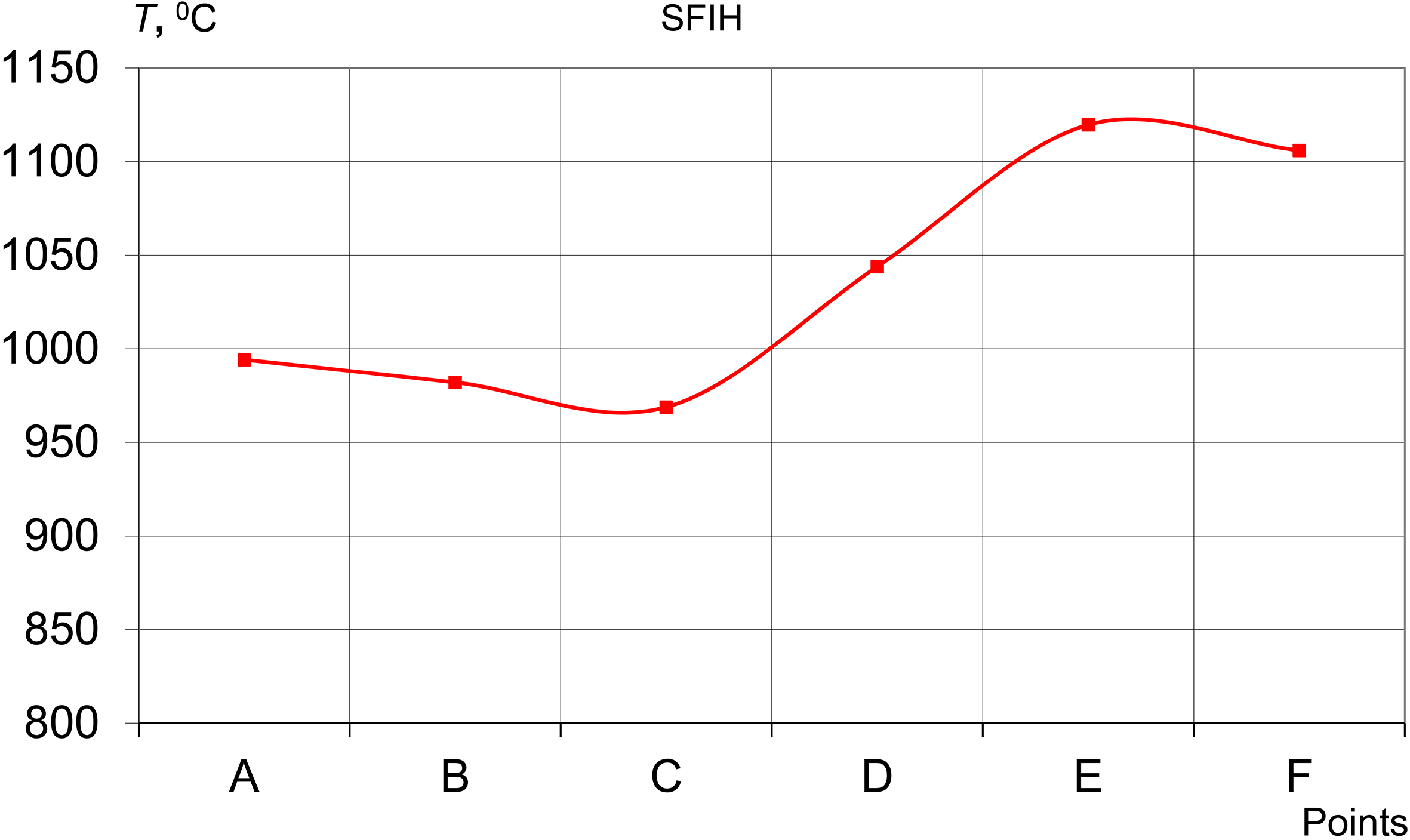
The average temperature in the thin hardened zone along the working surface of the tooth 953C. Taking into account that for the case the calculated velocity of induction heating 620 K/s the final temperature was still higher than Ac. The temperature distribution in the hardened zone was quite uniform, however near edges of the tooth too big temperatures of about 1050C were noticed. In the case of the CDFIH process the final temperature distribution after induction heating was presented in Fig. 9.
CDFIH process. Temperature distribution within the whole tooth after 5.2 s.
Temperature distribution along the line AF (see Fig. 6) for SFIH.
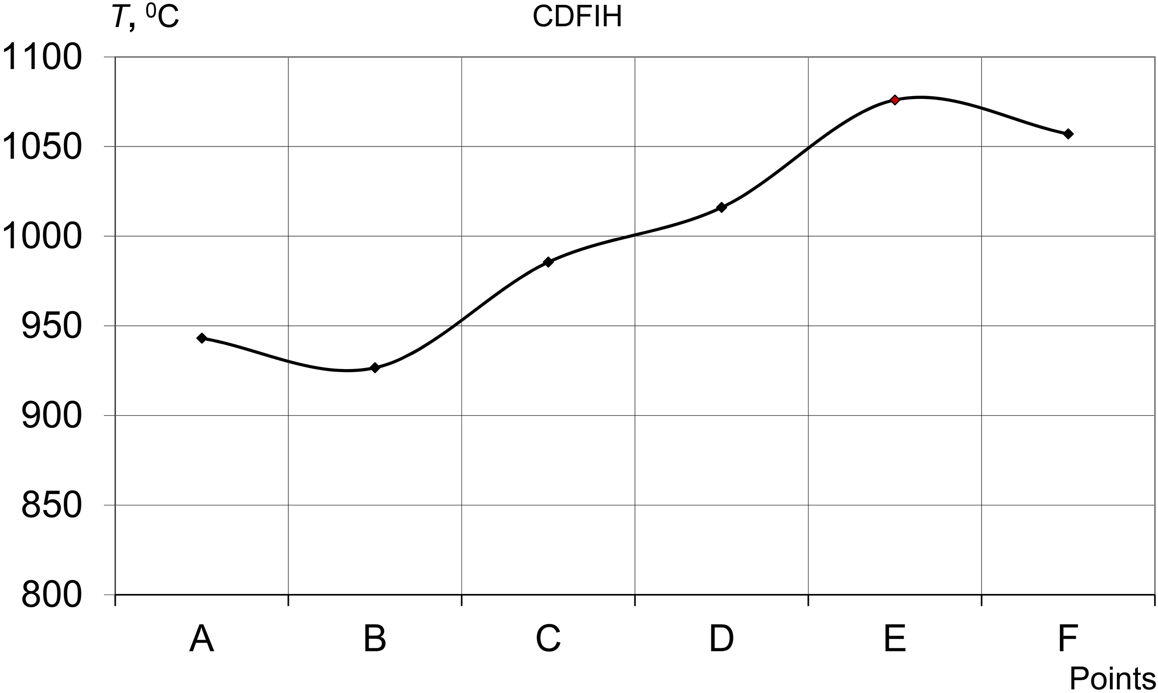
After the MF heating the average temperature within the thin zone 475C. It was sufficiently lower than the lower critical temperature Ac. After the HF heating the average temperature in the thin zone 933C, which was only slightly higher than Ac. Temperature distribution along line A–F for the SFIH and the CDFIH processes were shown in Figs 10 and 11.
Temperature distribution along the line AF for the CDFIH process.
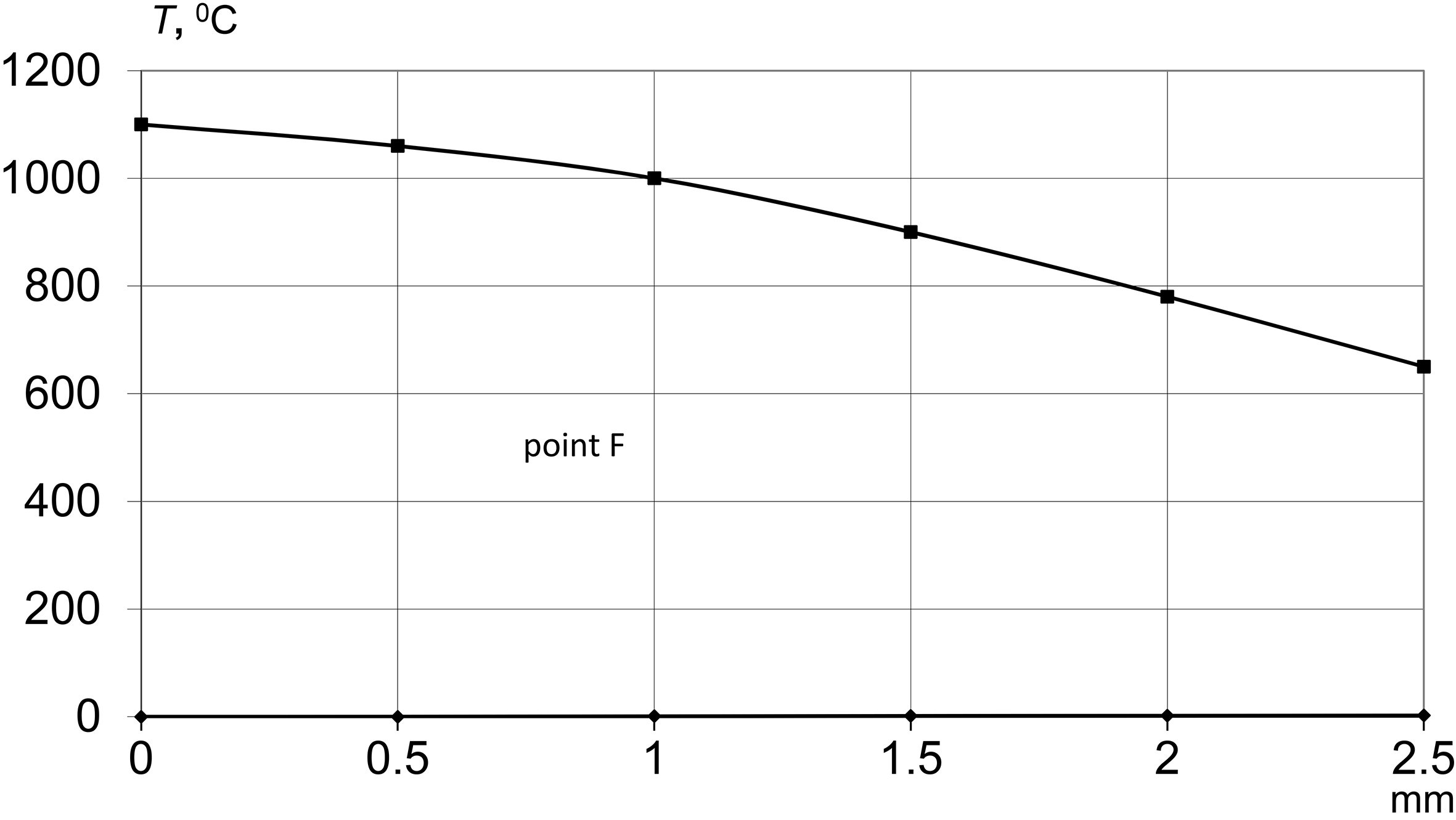
Temperature distribution in depth of the tooth for the CDFIH process in point F (see Fig. 6).
The temperature distribution in depth of the tooth for the CDFIH process was presented at Fig. 12.
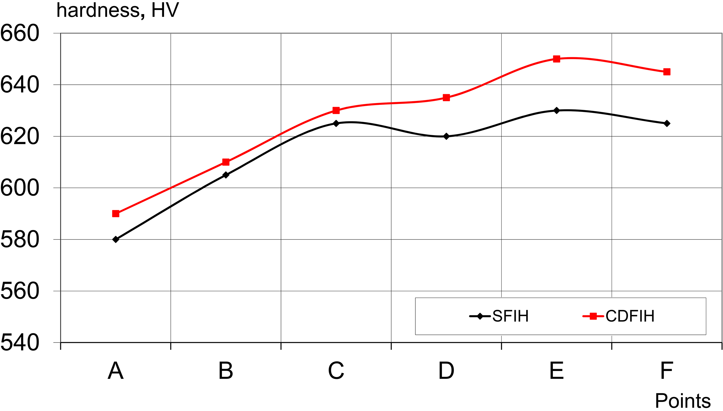
The calculated hardness distribution was presented in Fig. 13.
Hardness distribution along the line AF.
In both cases the hardness reached the expected level (600–645 HV). Smaller values were noticed in the area of the cut (580–600 HV). Bigger hardness values were achieved for the CDFIH process.
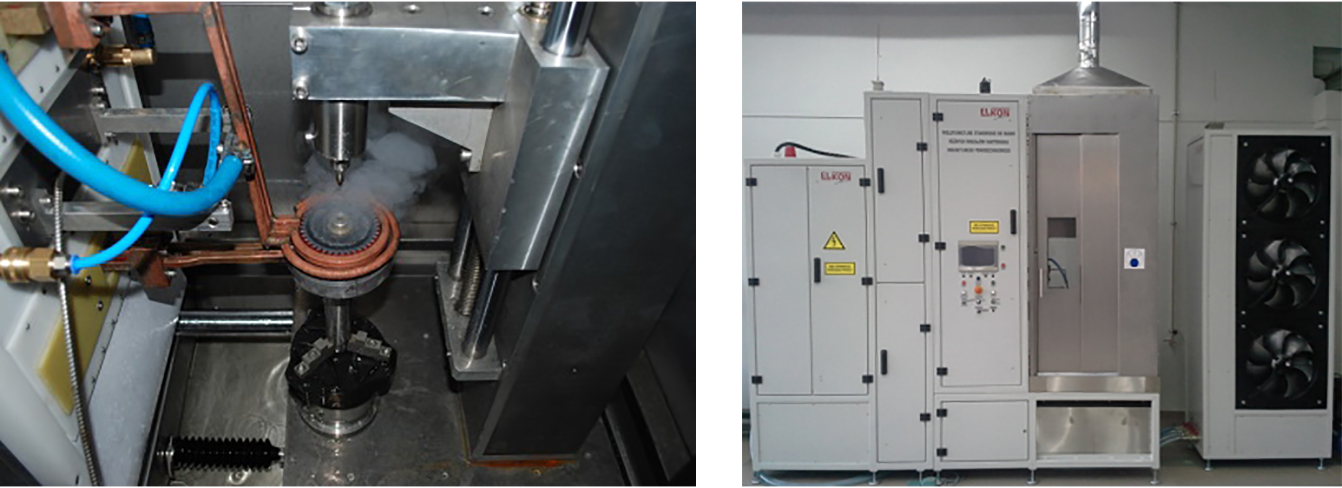
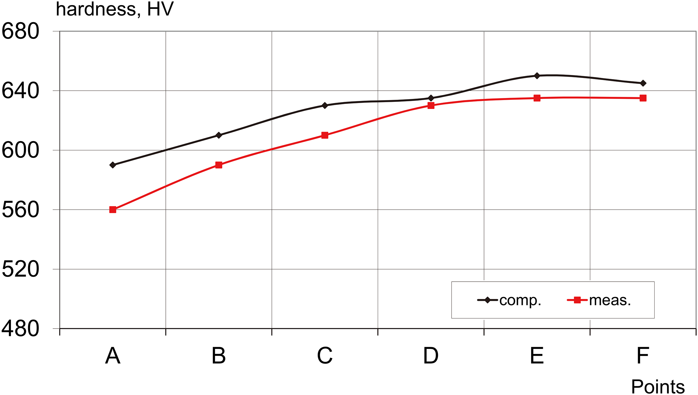
In order to verify the computations gear wheels were hardened at the experimental stand built in the Silesian University of Technology (Fig. 14). After the hardening gear wheels were tempered (2 hours in temperature of 160C). Comparison of hardness computations and measurements for the CDFIH process along the line AF (Fig. 6) was presented in Fig. 15.
Induction hardening system (left) and laboratory stand (right).
Comparison of computed and measured hardness distribution for the CDFIH induction hardening process.
Acceptable accordance (of about 5–8 %) between computations and measurements was achieved.
Summary
The paper deals with the analysis of the SFIH and CDFIH induction surface hardening of gear wheels. Flux 3D software for electromagnetic and temperature fields and some own numerical procedures for hardness and microstructure distribution were applied. Temperature dependences of material properties and convection heat transfer coefficient for cooling were taken into account. The modified upper critical temperature Ac was considered as dependent on the velocity of heating. Acceptable accordance between calculated and measured hardness distribution was achieved.
Footnotes
Acknowledgments
The paper was prepared within the project PBS2/A5/41/2014 supported by the National Center of Research and Development in Warszawa, Poland.
References
1.
BarglikJ., Mathematical modelling of induction surface hardening, COMPEL The International Journal for Computation and Mathematics in Electrical and Electronic Engineering4 (2016), 1403–1417.
2.
BarglikJ. and SmalcerzA., Influence of the magnetic permeability on modeling of induction surface hardening. COMPEL. The International Journal for Computation and Mathematics in Electrical and Electronic Engineering2 (2017), 555–564.
3.
SchubotzS. and NackeB., Modeling and verification of convective heat transfer coefficient for induction applications, International Journal for Electromagnetics and Mechanics53 (2017), 79–88.
4.
RudnevV. and TottenG., Induction Heating and Heat Treatment. ASM International, Materials Park, 2014.
5.
SchlesselmannD.NikanorovA.NackeB.GaluninS.SchonM. and YuZ., Numerical calculation and comparison of temperature profiles and martensite microstructures in induction surface hardening process, International Journal for Electromagnetics and Mechanics44 (2014), 137–145.