
Abstract
Conventional low-frequency electromagnetic wave (LFEM) transmitting antennas are enormous in size, which limits the application of LFEM in underground space. Rotating-magnet Based Mechanical Antennas can realize the miniaturization of low-frequency antennas, which is expected to bring new possibilities for underground electromagnetic detection or ground penetration communication. Firstly, this paper establishes a synthetic field method for solving the electromagnetic field of a rotating permanent magnet in the air-earth cross-domain case. The method equates the magnet as an orthogonal superposition of vertical and horizontal dipole sources, and the phase difference between vertical and horizontal dipole sources is 𝜋/2. Based on the half-space theory of multilayer planar media, the quasi-analytical solution of the electromagnetic field of the magnetic dipole in the case of air-earth trans dimensionality can be found by superposition. Secondly, based on the finite element numerical model, the trans-earth propagation characteristics of the electromagnetic field excited by the rotating permanent magnet across the air-earth dual domain are studied. At the same time, the radiation characteristics in the rotating plane of the permanent magnet are also studied. Again, this paper systematically investigates the influence of parameters such as earth conductivity, emission frequency, and propagation distance on the electromagnetic field propagation. Finally, the principle prototype is developed and experiments are carried out. The results show that the finite element numerical model established in this paper is correct, the experimental results are consistent with the theoretical values, and a field strength signal of 0.9 nT can be received at 20 m. The research work in this paper lays the foundation for the future use of mechanical antennas for electromagnetic detection and ground penetration communication.
Keywords
Introduction
Traditional wireless communication has the advantages of high transmission rate, large communication bandwidth, and low delay, which can meet most communication needs in daily life. In the underground, underwater, and other particular environments for communication tasks, due to the soil and seawater being a consuming medium, electromagnetic wave propagation will produce a time-varying electromagnetic field, which will form a conduction current in the medium, resulting in the loss of electromagnetic wave energy, and the higher the frequency of the electromagnetic wave in the consuming medium, the greater the attenuation [1]. Therefore, the traditional high-frequency electromagnetic waves can not meet some more extreme environments in communication needs. Low-frequency electromagnetic waves play a vital role in mine exploration, earthquake prediction, and emergency rescue communication [2,3]. However, in the previous research, to effectively transmit low-frequency electromagnetic waves, it is necessary to build several kilometers or even dozens of kilometers of ring antenna to transmit ultra-long-wave signals to realize the ground-penetrating communication, which occupies a large area, has a high cost of maintenance, and has low radiation efficiency.
In recent years, researchers have discovered several more convenient ground-penetrating communication methods, including current field, elastic wave and magnetic induction[4]. The current field ground-penetrating communication realizes information transmission by applying low-frequency electrical signals at the transmitting end and sensing electrical signals through electrodes at the receiving end. Based on this, Zhan Xu et al. established a path loss model for the current field ground-penetrating communication and tested the path loss of 3–10 Hz signals at 200 m and 400 m communication distances [5]. The U.S. Bureau of Geology and Mines first proposed elastic wave through-the-earth communication. It transmits information through the mechanical vibration of the elastic wave. Still, the current field and elastic wave through-the-earth communication methods are affected by the stratum, making the channel unstable. Therefore, they does not apply to the complex stratum, remaining currently in the stage of theoretical research with fewer applications [6–8]. The magnetic induction through-the-earth communication usually has more stable signal channel due to the earth's magnetic permeability is less affected by the geological structure. Tian et al. established a magnetic induction through-the-earth communication model and carried out simulation calculations for the demand of trans-earth transmission of voice and information [9,10]. However, to increase the received magnetic field strength, magnetic induction communication requires that the capacitance, inductance, and operating frequency of the transmitting and receiving circuits satisfy the resonance condition [11]. However, the resonance condition of magnetic induction communication is difficult to realize in underground space. To improve the transmitting efficiency, the transmitting antenna must be large enough, which brings great inconvenience to the deployment and use in underground tunnels with limited space [12,13].
The rotating permanent magnet type mechanical antenna as a new low-frequency means of communication is distinguished from magnetic induction trans-earth communication by the fact that magnetic induction trans-earth communication uses a coil energized with an alternating current to produce a changing magnetic field as a communication carrier to send information. Mechanical antennas, on the other hand, are mechanically driven to make a periodic movement of a charged body or a permanent magnet, which directly generates sinusoidal alternating signals, and the information is transmitted by receiving such signs at the receiving end [14]. Prasad first proposed mechanical antennas based on rotating permanent magnets and their simple array structures [15,16]. Fawole enhanced the strength of the electromagnetic field through the use of active bias, and the transmission distance and the transmission efficiency were both improved [17]. In the experimental process, the motor performance seriously limits the communication rate of the rotating permanent magnet low-frequency antenna. Barani et al. sandwiched the permanent magnet between two pairs of orthogonal bow-tie-shaped plates of materials with high permeability or added current-carrying coils with high permeability materials around the rotating permanent magnet to change the magnetic field distribution around it and thus improve the performance of the mechanical antenna [18,19].
Regarding theoretical research, Gong derived the radiation field of a uniform medium with a rectangular-shaped permanent magnet as the research object, analyzed the effect of medium parameters on transmission distance, and conducted experimental verification [20]. Based on the rotating magnetic dipole model, Shi and Zhou et al. investigated the magnetic field propagation characteristics of seawater-air semi-uniform infinite medium [21,22]. From the above studies, some progress has been made in researching mechanical antennas. However, more studies are still focused on theoretical modeling and the fabrication of in-lab prototypes. There is no research on the propagation of electromagnetic waves excited by mechanical antennas in the area of ground-penetrating communication.
The original intention of the mechanical antenna was to go for communication in occasions where traditional high-frequency wireless communication is not adapted. Existing research needs to consider its real application scenarios, and there are fewer theoretical analyses and verifications in complex environments. The rotating permanent magnet as a low-frequency communication means brings a new possibility for through-the-earth communication, so theoretical research on the propagation of electromagnetic waves excited by permanent magnets in the uniform half-space medium is necessary. This paper analyzes the synthetic field method for solving the electromagnetic field of a rotating permanent magnet in the air-earth cross-domain case. A finite element numerical model of the trans-earth propagation of electromagnetic waves excited by a rotating permanent magnet mechanical antenna across an air-earth medium is established using the COMSOL multiphysics field simulation software, and the radiation characteristics of the rotating permanent magnet in a uniform half-space are investigated. Finally, an experimental prototype was built and tested. Experimental results agreed well with the theoretical results. This paper lays the foundation for applying a rotating permanent magnet low-frequency antenna for ground-penetrating communication.
Theory and methodology
Principles of communication
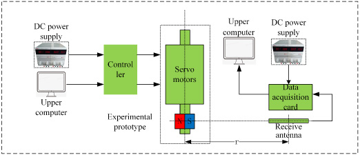
As shown in Fig. 1 is a schematic diagram of a rotating permanent magnet mechanical antenna penetrating communication; the system is divided into two parts, including transmitter and receiver, transmitter by motor, magnet, and upper computer control device. The upper computer encodes the transmitted information into a drive signal that can be recognized by the motor. The motor drives the magnet rotation, forming a sinusoidal electromagnetic field which contains the information to be transmitted. A high-precision weak magnetic field sensor is used to receive the magnetic field signal. Finally, the required communication signal is obtained by filtering and demodulating the composite signal. For ease of analysis, this paper assumes that the conductivity of the earth is uniform and isotropic.

Schematic diagram of ground-penetrating communication using mechanical antenna.
The magnetic moment of a permanent magnet can be expressed by
Where B
r
is the residual magnetic strength of the permanent magnet, V is the permanent magnetic volume, 𝜇0 is the magnetic permeability in vacuum. When the solution area is far larger than the magnet, the magnet can be regarded as a magnetic dipole, the static field distribution of the magnet around it depends on its magnetic dipole moment, and the equivalent relationship between the permanent magnet and the magnetic dipole moment can be obtained (2):
where qm
is the effective magnetic charge. According to Fig. 2, the magnetization direction of the magnet is along the y-axis. When the magnet rotates around the x-axis direction, it can be equivalent to the superposition of a horizontal magnetic dipole pointing to y-axis and a vertical magnetic dipole pointing to z-axis. The feed phase of the magnetic dipole in the z direction lags behind that of the dipole in the y direction by 90°. In literature [23], analytical solutions of horizontal and vertical magnetic dipoles in infinite uniform half space were obtained respectively. When both the magnetic dipoles and the observation point are located on the surface of the earth, the magnetic components of the horizontal magnetic dipole are given by
where ϕ is auxiliary function, ρ is the cylindrical coordinate of the field point, m is the the magnetic dipole moment of the magnet defined in ((1)), I and K are the modified Bessel functions of the first and second kinds respectively, and the lower corner script represents the order respectively, k is complex wave number, which is defined by
where, kR
and kI
are the real and imagary parts of the wave number respectively, μ is the magnetic permeability, ϵ is the dielectric constant, σ is the electrical conductivity. Then, by superimposition principle, the analytical solution expression of magnetic field generated by a rotating magnet in homogenous half space is obtained by
Moreover, it should be noted that the z axis is oriented upwards here.
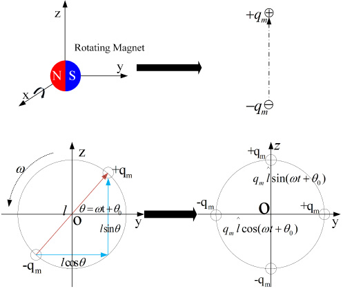
Equivalent process of rotating magnet and orthogonal magnetic dipoles.
COMSOL is a multi-physics field simulation software. The first step is to create a geometric model, as shown in Fig. 3, and then assign material properties. After the modeling is completed, different equations are chosen in other areas, and then the mesh is dissected. In the area of interest, the mesh needs to be dissected a little smaller so that the number of the mesh is as large as possible, and the results of the calculations will be more accurate. The grid can be sparsely dissected in less exciting areas, and the computation time will be greatly reduced. The model in Fig. 3 has 26,162 mesh elements, 4,762 mesh vertices, and an average cell mass of 0.6508. The CPU is Intel(R) Core(TM) i5-8250U CPU @ 1.60GHz 1.80 GHz. The RAM capacity is 8GB. The CPU usage is about 40-50%, and the RAM usage is about 4.5 GB. The selected solver is a transient solver; the simulation time is 0–0.01 seconds, the simulation time step is 20 steps, and the computation time is 48 minutes.
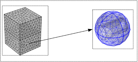
Three-dimensional mesh division diagram of mechanical antenna.
The left side of Fig. 3 is a mesh division diagram of the finite element model of the mechanical antenna, the right side is an enlarged view of the middle magnet area, and the module selected in the process of rotating permanent magnet modeling is the rotating mechanical magnetic field module, which is mainly used to analyze rotating devices such as motors, and its physics solving equation is more in line with the mechanism of the mechanical antenna of the rotating magnet. The magnet is wrapped in a spherical air domain (simulating the air gap in the motor) , as shown in the right side of Fig. 3. Set the ``physical field" to ``magnetic flux conservation" within the magnet domain and the surrounding spherical air domain to solve the magnetic scalar potential Vm
and thus the magnetic field. The governing equation is expressed by Eq. (7). The interface between the permanent magnet and the air is set a ``consistent boundary pair" to ensure continuous magnetic field.
The solution area outside the air sphere can be set according to the actual simulated environment. If the medium is air, set ``physical field" to ``magnetic flux conservation", add ``zero magnetic scalar potential" specification, and solve the magnetic scalar potential according to Eq. (7). Correspondingly, if the medium is the earth, set ``physical field" to ``ampere's theorem" and add ``magnetic vector potential" specification to solve the magnetic vector potential according to Eq. (8). The outermost domain is set to ``infinite element domain".
Verify the correctness of the finite element simulation results
To verify the theoretical correctness of the ground-penetrating communication method of mechanical antenna described in this paper, comparing the finite element simulation results with the analytical model is adopted. Select the same parameters in the simulation model and analytical model, and model it in the simulation software, as shown in Fig. 3, set the relative permeability of the air to 1, the relative permittivity to 1, the conductivity to 0 S/m, the conductivity of the earth to 0.01 S/m, other properties are the same as air. Let the magnet rotate at a frequency of 100 Hz. The analytical solution is obtained according to Eqs ((3))--(6). As shown in Fig. 4, the solid line is the result of the analytical solution, and the circle-dotted line is the result of the finite element. The two lines agree well with each other, which verifies the correctness of the theoretical model.

Comparison of semi-uniform spatial analytical solution and finite element method.
After verifying that the simulation model is correct, considering that the advantages of mechanical antennas for ground-penetrating communication should be portable, small, two-way communication, it is necessary to verify further whether their propagation characteristics are consistent in the two-way communication process through the earth and the air. We should first clarify whether the magnetic field signals received in the two-way communication process is equal. In the first case, the magnet is placed horizontally on the earth surface, and the receivers are located 100 m, 200 m, and 300 m underground directly below the magnet. In the second case, exchange position of the magnet with each receiver location individually. The magnetic flux density amplitudes in the two cases are obtained, respectively. The results obtained are recorded in Table 1.
Ground-penetrating bidirectional communication signal amplitudes
Data analysis from the simulation results, regardless of whether the emission source is in the earth or air, through the same propagation path, the signal amplitude received is the same, which is consistent with the phenomenon described by the electromagnetic field reciprocity theorem. Only one of the two cases needs to be considered in the simulation process. In the subsequent analysis, we only consider the situation where the transmitter is on the surface and the receiver is underground.
The magnetic field strength in the rotational plane in the near-field range is greater than the magnetic field strength on the rotation axis, so it is more concerned about some characteristics of magnetic field radiation in the rotational plane and only magnetic fields in the rotation plane is shown. According to the method described in the second section, some simulation parameters are set: the height of the magnet is 6 cm, the radius is 1.75 cm, the magnetization direction is the y-axis, the residual magnetic strength is 1.2 T, the rotation axis is the x-axis, and the speed is 100 r/s. In order to more clearly describe the radiation characteristics of the mechanical antenna, two-point probes are set up at (0,0.8,0) and (0,0,0.8); the simulation results are shown in Fig. 5 and Fig. 6. Figure 7 depicts spectrograms of each component of the magnetic flux density. From Fig. 5, it can be seen that at the same distance from the magnet in the plane of rotation, the magnetic flux density amplitude is the same. Still, for different positions, the phase change is different, and it can also be seen that its maximum magnetic flux density is about 21 μT at a distance of 0.8 m from the magnet.
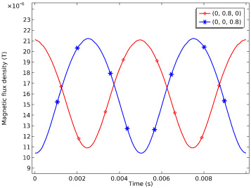
Variation of flux density mode over time at the same distance from the magnet center.
The modulus and three components of the magnetic flux density at point (0, 0.8, 0) are shown in Fig. 6, and their spectrum is shown in Fig. 7. It can be seen that the y component is the largest, the z component is second, the x component is the smallest, the y and z components differ by 90 degrees in phase, and the frequency of all three components are the same as the rotation frequency. Still, the modulus is the superposition of the three components, and the frequency is about twice the rotation frequency.
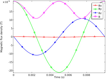
Time domain plot of the magnetic flux density component at point (0, 0.8, 0).
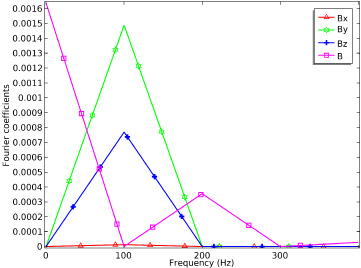
Frequency domain plot of the magnetic flux density component at point (0, 0.8, 0).
To further intuitively see the change in the relationship between the three components generated by the rotating magnet in different positions and at different times in the rotation plane, the polar coordinate diagram of the three components and amplitudes of the magnetic fields in the rotation plane is drawn in Fig. 8. The conclusion can be removed from the chart: The radiation main axis directions of By and Bz parts are perpendicular to each other in the rotation plane, while the Bx component is independent of the azimuth angle. Although the flux density modulus at the same distance from the magnet center will not reach its maximum value simultaneously, their spatial distribution is approximately symmetric.
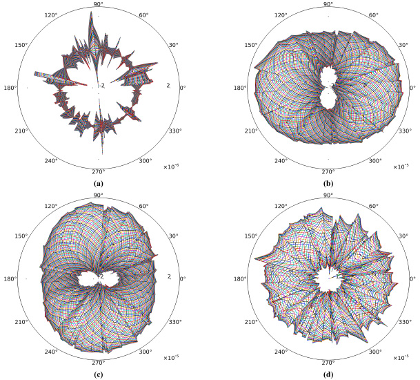
Spatial distribution of magnetic induction B and its three components in the rotation plane. (a) Bx component. (b) By component. (c) Bz component. (d) Field B.
Communication distance
The reciprocity theorem has been verified in Section 3.1, so subsurface emission is not considered when analyzing the attenuation of magnetic field signals with distance. In the simulation model, the relative permeability of air is set to 1, the relative permittivity is 1, the conductivity is 0 S/m, the conductivity of the earth is set to 0.01 S/m. The rotation rate of the magnet is 100 Hz. The receiving points are located underground directly below the magnet. The attenuation curve of the magnetic flux density with distance is plotted in Fig. 9. Some typical magnetic induction values in the figure is listed in Table 2. The magnetic induction intensity is 1 μT at depth of 2.2 m, 1nT at 23.07 m, 1 pT at 203.45 m. It suggests that when the distance increases by 10 times, the amplitudes of the magnetic induction intensity roughly attenuates 1000 times. That is the magnetic induction intensity attenuates approximately cubically with the increase of depth. It must be noted that the real decay rate of magnetic induction intensity is a little faster than cubic decay from the further analyis of these values. It is due to the influence of eddy current effect in the earth.
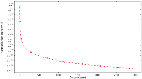
Variation of magnetic flux density with distance.
Amplitudes of magnetic flux density at different distances
The formation is a very complex medium; different geological environments have additional water content, resulting in different conductivity, and the rotating magnetic field will produce induced electromotive force in the consumable medium. The electromotive force forms eddy currents inside the formation, the alternating magnetic field excited by the eddy current is opposite to the direction of the rotating magnetic field of the magnet, resulting in the attenuation of the ground-penetrating alternating magnetic field, and the attenuation coefficient caused by the eddy current effect can be expressed as:
To study the response characteristics of the magnetic field more clearly, the principle of a single variable is adopted; only one parameter is changed each time. When analyzing the frequency, the fixed geodetic conductivity is 0.01 S/m. The frequency is set to 100 Hz when examining the influence of conductivity, and the magnetic flux density change curves at three points are plotted in Fig. 10 and Fig. 11.
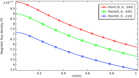
Effect of conductivity on magnetic flux density modulus.
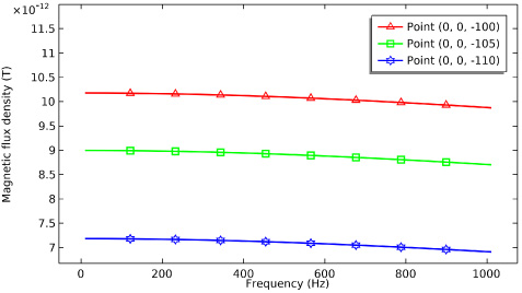
Effect of frequency on magnetic flux density modulus.
As shown in Fig. 10 and Fig. 11, the magnitude of the magnetic flux density decreases with the increase of the conductivity or the frequency. The law of the two sets of data is roughly the same as the law of the analytical solution reaction, and the decay of the magnetic field becomes faster with the increase of frequency and conductivity. The main reason is that because the rotating magnetic field will induce a vortex electric field of the same frequency on the surface, the secondary magnetic field formed by the electric field is opposite to the direction of the original magnetic field, resulting in further acceleration of the decay of the magnetic field. The influence of conductivity on magnetic flux density is more sensitive, increasing by the same multiple. Conductivity has a more significant impact on magnetic flux density, and conductivity and frequency together determine the attenuation coefficient of magnetic flux density over the distance.
After a single simulation of frequency and conductivity, several typical frequency values and conductivity values are selected for further analysis. The magnetic flux density amplitudes at different conductivities and frequencies as functions of the distance are plotted in Fig. 12.
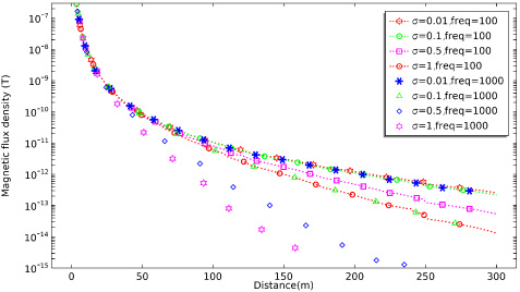
Magnetic flux density amplitudes change with distance at different operating frequencies and conductivities.
With the increase of frequency and conductivity, the magnetic flux density attenuation becomes larger, the distance of ground-penetrating communication decreases, it can be seen that the curve of 𝜎 = 0.1 S/m, f = 100 Hz and the curve of 𝜎 = 0.01 S/m and f = 1000 Hz coincide together, 𝜎 = 1 S/m, f = 100 Hz curve coincides with the curve of 𝜎 = 0.1 S/m, f = 1000 Hz, which indicates that in ground-penetrating communication, the attenuation coefficient of the magnetic flux density modulus is inversely proportional to the product of frequency and conductivity, and corresponds to the ground-penetrating skin effect formula.
Experimental configuration
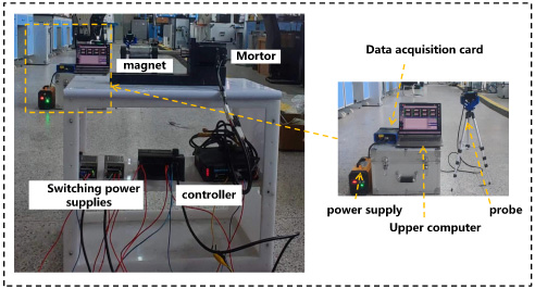
Schematic diagram of the rotating permanent magnet mechanical antenna experimental prototype.
Based on the above analysis, the test prototype shown in Fig. 13 was designed and developed, and the equipment mainly includes: upper computer and controller, servo motor, and fluxgate meter, data acquisition card module, etc. At this stage, due to the limitations of the experimental environment, it is impossible to carry out through-the-earth communication experiment. However, we conducted experiments to verify the propagation characteristics of the magnetic field in the horizontal direction on the surface.
Experimental process diagram of rotating permanent magnet mechanical antenna.
The experimental process is shown in Fig. 14. Firstly, the electronic gear ratio of the motor is set to 100; when the control terminal sends 100 pulses, the motor rotates once. Then, the controller of the motor communicates with the host computer, the host computer sends commands to make the motor move. The switching power supplies for the controller. The right side in Fig. 14 is an enlarged picture of the receiving end. The probe is placed at the same height level as the magnet, and the received signal is transmitted to the data acquisition card; the card processes the data and then sends it to the upper computer to display and save it.
The near-zone magnetic field of the rotating permanent magnet-type mechanical antenna is strongest in the plane of rotation, so the receiving antenna is placed in the rotation plane of the magnet, perpendicular to the rotation axis of the interest. The receiving antenna was moved from a distance of 0.75 m to 20 m. The magnetic field of different distances r was measured. The attenuation curve of its magnetic flux density with distance is obtained.
The speed of the servo motor is set to 2400 r/min, and the experimental distance is tested from near to far. Figures 15 and 16 show the time-domain waveforms of the three magnetic flux density mode components at r = 1.5 m. Figure 15 shows that before removing the DC component, the three components of the magnetic flux density change according to the sinusoidal law as the simulation results. Still, it can also be seen that each component is superimposed with a significant DC component, which is the effect of the geomagnetic field and other DC interference components. Figure 16 shows the waveforms of the experimental data after removing the DC component. From the waveforms, the experimental results correspond to the simulation results. The magnitudes of the three components are different, and the y and z components have a phase difference of 90°, which verifies the correctness of the simulation results.
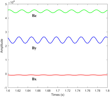
Measured magnetic flux density without removing the DC component.
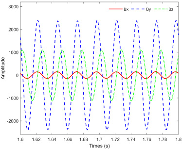
DE-DC waveforms of measured magnetic flux density.
Figure 17 shows the spectrum analysis of the measured magnetic field. It can be seen that in the actual environment for the detection, in addition to the signal waveform 40 Hz, there are also a large number of harmonic interference components, mainly for the 50 Hz industrial frequency and its odd harmonic components, such as the figure of the 150 Hz, 250 Hz, and other harmonic components.
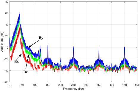
Spectrogram of the measured magnetic flux density.
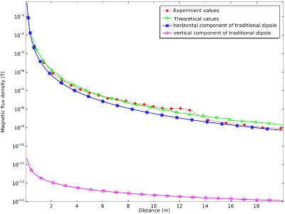
Comparison of measured magnetic flux density with theoretical values and conventional antennas.
Move the probe’s position, change the distance r, record the experimental data to plot the attenuation change of magnetic flux density with distance in its maximum direction, and compare with the theoretical analytical solution and the traditional dipole antenna. As shown in Fig. 18, the analytical solution matches the measured value relatively well, which verifies the correctness of the theoretical model. At the same time, from the experimental results, the signal strength is still 0.9 nT at a distance of 20 m, which indicates the feasibility of the rotating magnet-mechanical antenna for communication in the near-field range. By comparing the graphs of the traditional dipole antenna and the rotating permanent magnet mechanical antenna with the distance, the magnetic flux density of the rotating permanent magnet antenna is slightly larger than the horizontal component of the traditional dipole antenna, and is about five orders of magnitude larger than the vertical component of the traditional dipole antenna, which further illustrates the advantages of the rotating permanent magnet mechanical antenna in the low-frequency communication.
This paper studies the propagation characteristics of mechanical antennas for ground-penetrating communication. The rotating magnet is equivalent to a pair of orthogonal magnetic dipoles with a phase difference 90°. The analytical solution of the magnetic field generated by the rotating magnet in semi-uniform infinite space is obtained by the superposition of two magnetic dipoles, the correctness of the theory is verified by the finite element method, the model of ground-penetrating communication is established, and the radiation characteristics in the plane of rotation are analyzed. The influence of frequency and conductivity on the attenuation characteristics of magnetic fields was studied. Finally, the experimental prototype was developed, and the results were analyzed and the experiments showed that the developed prototype could receive a field strength signal of 0.9 nT at 20 m.
Due to the experimental environment constraints, we did not conduct the ground-penetrating experiment. The theoretical model established is relatively simple; the earth is regarded as a uniform conductive medium, and the actual communication environment is much more complex than the theoretical model. In the follow-up research and analysis, the theoretical model needs to be improved to be more in line with the natural environment. At the same time the experimental equipment should be optimized so that it can become a practical way of ground-penetrating communication.
Footnotes
Acknowledgements
This work was supported by the Research Fund of Institute of Advanced Electromagnetic Drive Technology of Qilu Zhongke Electrical Engineering. We would also like to thank the reviewers for their valuable comments on this article and the editor for their diligent proofreading.