
Abstract
An automatic design optimization of a wireless power transfer system is performed using Monte Carlo tree search (MCTS). Several key factors, i.e., the compensation network, shapes and geometrical parameters of the coils are determined after searches, in order to achieve the high transfer efficiencies for coaxial aligned and misaligned cases. The improved Selection policy in MCTS, called first play urgency (FPU), is implemented for optimization. It proves to be a more promising technique for finding optimal solutions when the searching volume is limited, compared with the original MCTS with using the upper confidence bound applies to tree (UCB1).
Introduction
Wireless power transfer (WPT) systems have received great attention for charging various items ranging from cell phones to electric vehicles [1–3]. Among multiple key characteristics for evaluating WPT systems, the transfer efficiency stands out as one of the most critical one. Coinciding with transfer efficiency, typically, a constant output voltage on the secondary part of the WPT system is also expected, in order to supply a steady power to the subsequent load. Based on the reasons mentioned above, when designing a WPT system, our primary focus lies in the transmission efficiency of the system and the characteristics of a constant voltage output. Unfortunately, when addressing the issue of designing a WPT system comprehensively, numerous variable factors need to be taken into consideration, such as the selection of a compensation network, sizes of transmitting and receiving coils, and so on, undoubtedly amplifying the complexity of the design.
Therefore, designing a WPT system with high transfer efficiency and constant output voltage poses significant challenges. With the development of the artificial intelligence (AI), it is feasible to analyse and design WPT systems in a more streamlined and efficient manner, thereby predicting the performance or achieving performance enhancements. In [4], the neural network-based artificial intelligence is implemented for the estimation of the accurate acquisition in terms of the receiver. In addition, A class-E power amplifier for WPT applications is designed in [5] using the neural network, combined with imperialist competitive algorithm, genetic algorithm, and so on. In [6], an optimal efficiency tracking model is proposed based on the power control technique, using machine learning, for overcoming the efficiency drop caused by variant impedance. In [7], the neural network is built for the designing of the three-dimensional core in WPT systems. However, this approach is only applicable to cases with coarse grids of the core. As the grid becomes finer, it also implies a significant increase in the number of input variables, leading to a substantial rise in both computational complexity and difficulty in interpretation. A coil design is carried out in [8] for the WPT robust analysis, based on the improved Tabu search.
Regarding to the multi-objective design on WPT systems, the particle swarm optimization is successfully implemented [9–11] for designing W-type road, the shields, and couplers. In [9], the response surface is also applied for approximation. Alongside particle swarm optimization in [10], the non-dominated sorting genetic algorithm II is also employed for comparable research. However, the aforementioned literatures are focused on the design of a specific component, such as the coil or a shielding layer, without considering other aspects of the WPT system, such as the selection of topology, which may be either overlooked or predetermined. In [12], four widely used couplers are studied and compared after optimization through the particle swarm optimization, however similarly with [9–11], the selection of topology is out of considered.
Monte Carlo tree search (MCTS) is an AI method, for finding optimal solutions by building a search tree through the process of Selection, Expansion, Simulation, and Backpropagation [13]. It can make a trade-off between the exploitation and the exploration when making decisions, therefore, it is suitable for optimization problems. Now it has been successfully applied to the optimization in electrical applications such as motors [14], inductors [15], and so on. Furthermore, MCTS is not only suitable for the single-objective optimization problems in the aforementioned examples, but also applicable to multi-objective optimization, such as the designing sampling robot in the field of environmental monitoring scenarios [16] and the permanent magnet motor [17]. It is worth mentioning that MCTS can take selection of electrical topologies and parametric optimization for the geometry into consideration, which is highly suitable for solving optimization problems of WPT systems.
All these examples mentioned above are all based on the upper confidence bound 1 (UCB1) selection strategy [18]. It works well for cases when nodes are frequently visited trough the root to the leaf. Unfortunately, when the nodes are far from the root, or the searching volume is small, UCB1-based MCTS tends to be more exploratory, leading to lack of utilization on the exploitation which uses the obtained searching results, at the initial searching phase.
To overcome this issue, in this paper, we propose an approach to design WPT systems, using MCTS, based on the improved selection policy called first-play urgency (FPU) [19]. By comparing the UCB1 selection strategy, we have validated that more optimal results can be achieved using this improved algorithm when the searching times are limited, meaning it makes more efficient use of the exploitation feature. In other words, it is more possible to find a better optimal solution when searching times are low, compared with UCB1 policy.
This paper is organized as follows: in the second part, the detailed design process for optimizing WPT systems is given. In the third section, the optimization problem is depicted, and optimal results are given for demonstration. Finally, in the fourth section, some conclusions are drawn.
Optimal design process
Modelling approach
Circuit topology of the WPT systems
Prior to the introduction on the process of designing and optimizing, it is essential to offer a brief overview of the WPT system. A typical WPT system for automatic guided vehicles consists of the several components shown in Figure 1. It includes a DC power source V in for supplying electrical energy to the whole system, an inverter with the aim of converting direct current power into alternating one, an electrical topology T which includes the compensation network for achieving impedance matching and couplers, a full-bridge rectifier for converting the alternating current back to the direct one, a capacitor C f for smoothing the rectified DC voltage, which helps providing a stable output voltage to the load, with the resistance R load . All the constants for the electrical circuit of a WPT system is listed in Table 1 [20].
With regarding to the topology T presented in Figure 1, it consists of transmitting and receiving coils which will be introduced in Section 2.1.2, and various components and adjustments, such as capacitors and inductors, to achieve the resonance and the impedance matching between the coils. Series compensation (short for S) is commonly used as one of the fundamental topologies. Besides, as multi-resonant compensation networks, the inductor-capacitor-inductor (LCL) and the inductor-capacitor-capacitor-inductor (LCCL) topologies are frequently employed. These structures are either employed as the primary or the secondary sides in the WPT system, in conjunction with series compensation, or they are simultaneously utilized in circuits at both the primary and secondary sides to achieve impedance matching.
In this paper, S topology, LCL topology, and LCCL topology are employed for analysis. Without loss of generality, S-LCL and S-LCCL topology are analysed in the following parts, incorporated in the WPT systems, as shown in Figures 2(a) and 3(a). This allows us to derive the circuit-related component design guidelines for S topology, LCL topology, and LCCL topology. In Figure 2(a) and Figure 3(a), L1, L2 and M represent the self-inductances of the transmitting and receiving coils, and their mutual inductance respectively, R1 and R2 are the internal resistance of the transmitting and the receiving coils introduced in Section 2.1.2. In addition, V ab and I ab are the input voltage and current of the compensation network, V cd and I cd are the output corresponding ones after the compensation network, marked in Figure 1.
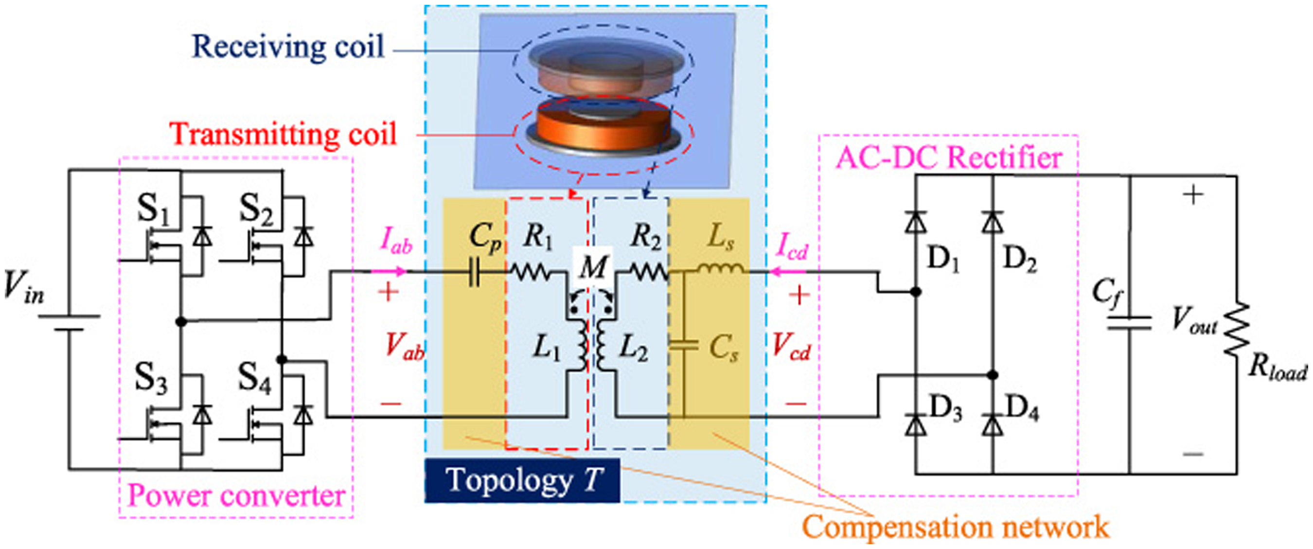
Schematic of a WPT system (the S-LCL type of the compensation network is shown as an example).
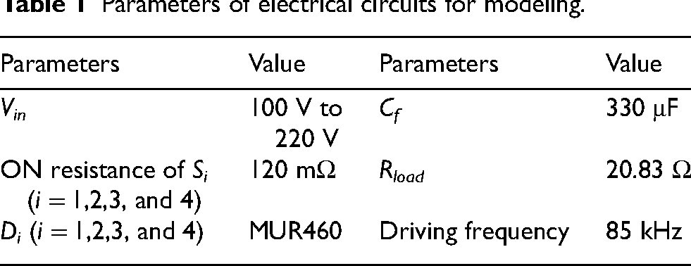
Parameters of electrical circuits for modeling.
Let us suppose that L1, L2M, R1 and R2 are known, and assume that V ab is a sinusoidal voltage with the frequency f = 85 kHz (angular frequency ω = 2πf), then their simplified equivalent electrical models are shown in Figure 2(b) and Figure 3(b), respectively, where V r and V s are the induced voltage by the secondary and the primary side. Next, based on the T-equivalent models, the resonant relationship for components in S topology, LCL topology and LCCL topology can be given sequentially.
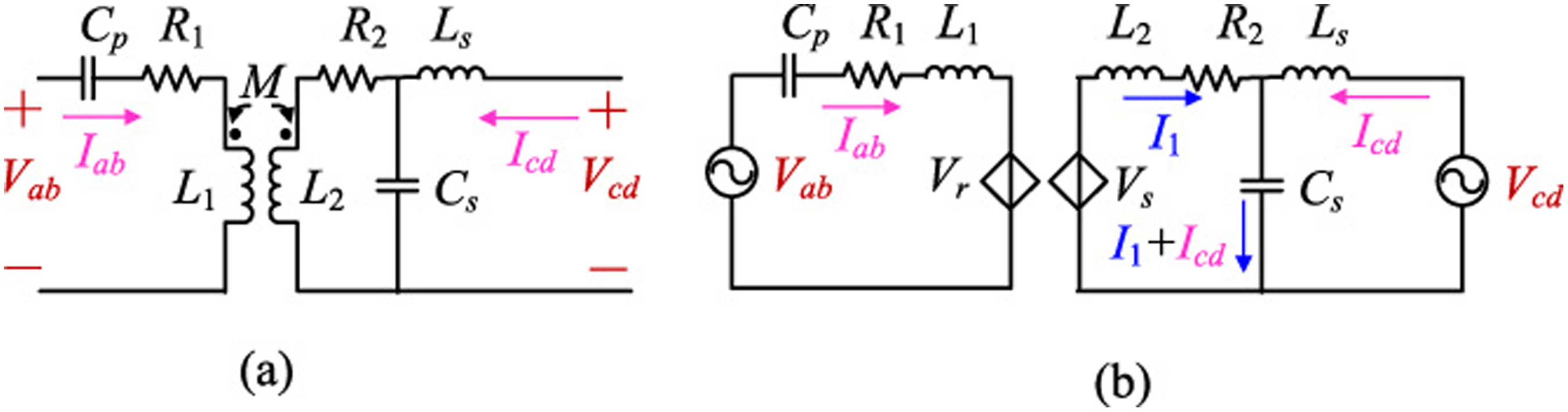
Model of S-LCL compensation network. (a) S-LCL topology. (b) T-equivalent model.
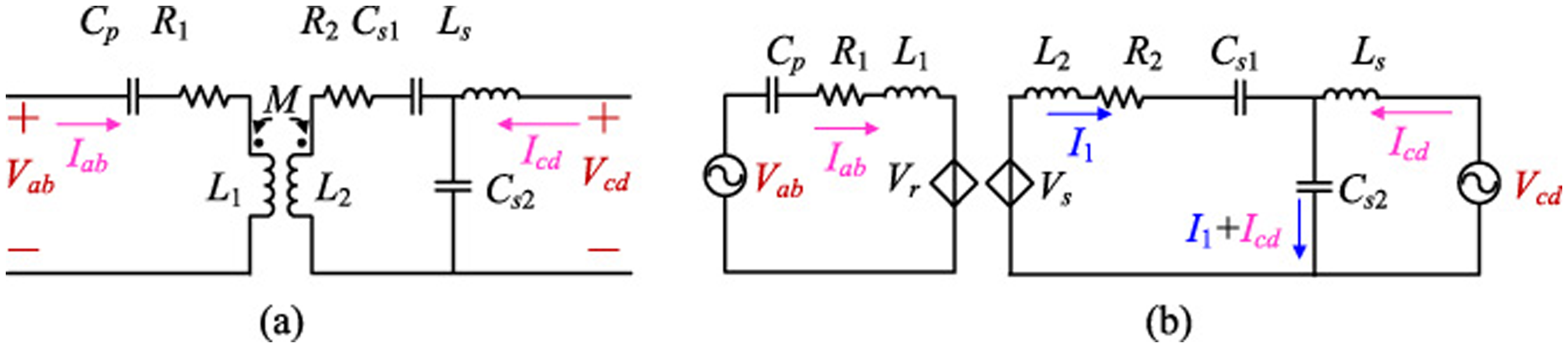
Model of S-LCCL compensation network. (a) S-LCCL topology. (b) T-equivalent model.
According to Kirchoff’s Law, we can obtain the relationship between its compensation capacitance and coil inductance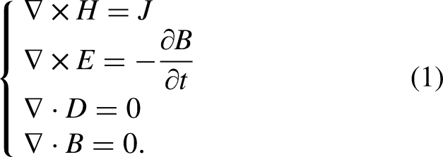

Regarding to LCCL in Figure 3(b) at the secondary side, the relationship between its compensation capacitance and coil inductance is
As is widely known, transmitting and receiving coils, which includes ferrite core and turns of coils, are the critical components in WPT systems for the function of inductive coupling. A commonly used coil configuration is the T-type, which means the core is of T shape in the cross-sectional view, as shown in Figure 4. Tightly wound around the external surface of the core, coils of the transmitting and receiving ports are several turns of copper-made Litz wire, with square shape in the cross-sectional view. The Litz wire is coated with an insulating layer on the outside, leading to the assumption that the current applied to the coils is uniformly distributed.
In ideal conditions, the transmitting coils and receiving coils are coaxially aligned, just as illustrated in Figure 4(a). However, during practical charging, often there is some misalignment between the transmitting coil and the receiving coil due to impropriate operations, shown in Figure 4(b), which would affect the value of inductances. To analyse the comprehensive system characteristics of WPT in both ideal and practical scenarios, this paper considers two modes: one with the transmitting coil and receiving coil in a coaxial alignment and the other in a misalignment.
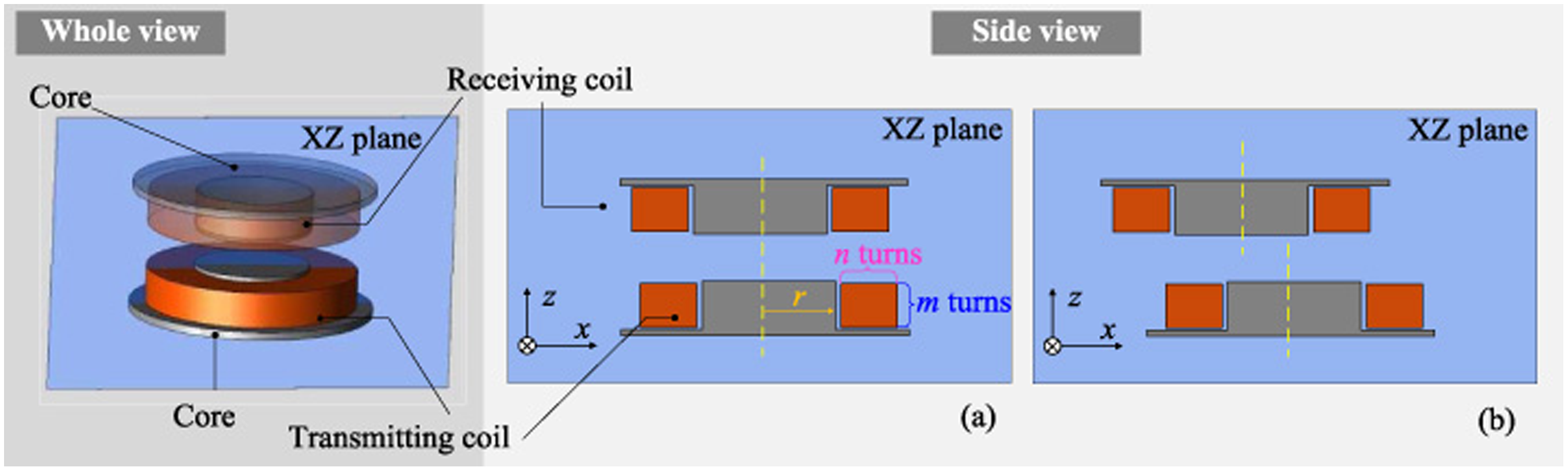
Structure of the transmitting and the receiving coils. (a) Coaxial alignment between the transmitting and the receiving coils. (b) Misalignment case.
According to calculations presented in the literature [20], which is based on the homogenization technique and finite element method (FEM), the value of R1 and R2 are in the scale of mΩ. Due to the minimal impact of coil losses, here we set R1 and R2 as constants and select the value of 130 mΩ from [20] for modelling in this paper.
Additionally, in this paper, with using the structures of transmitting and receiving coils in Figure 4, We obtain results of L1, L2 and M through the finite element method, under the harmonic analysis for both cases of the coaxial alignment and the misalignment, at the frequency of 85 kHz. Then, based on these results, and with the help of the neural network algorithm illustrated in Figure 5, surrogate models for predicting L1, L2 and M for the coaxial alignment and the misalignment cases are finally established. As shown in Figure 5, two layers of the neural network are used, with 10 neurons for the hidden layer. Neuron calculate a weighted sum adding the bias, and the activation function tanh is used afterwards. Then the output layer is linked to the hidden layer which has one neuron for desired output, that is, L1, L2 and M in this paper.
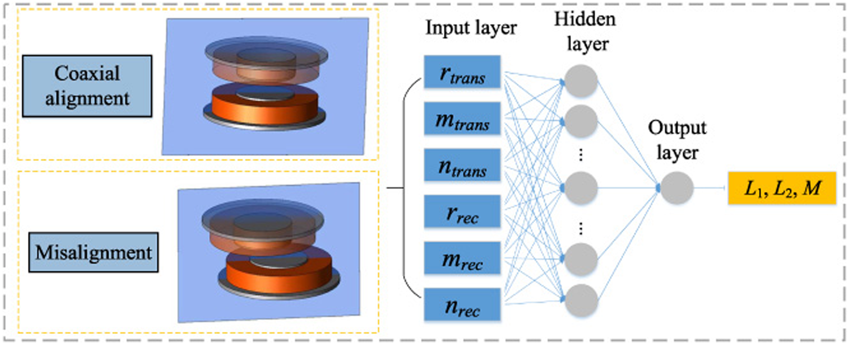
Structure of 2-layer neural network for building the surrogate model.
Combined with the design process in Section 2.1.1, all the parameters in the circuit of the WPT system can be determined once the circuit topology is decided. Then the transient performance of the WPT system can be obtained based on the simulation in the platform of Matlab SIMULINK. Finally, the efficiency, and the output voltage v cd under coaxial aligned and misaligned cases can be obtained.
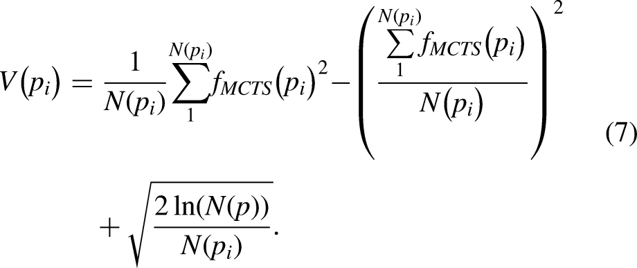
Before optimization, it is necessary to clarify the design target. In this paper, we aim at designing a WPT system for obtaining the highest transfer efficiency. As mentioned above, high transfer efficiencies under both the coaxial case , and the misalignment case between transmitting and receiving coils, are pursued. Simultaneously, the output voltage on the load is required to be constant at 50 V, and the rated load power is 120 W. Mathematically, the objective (designated by f
MCTS
) can be written in the following equation: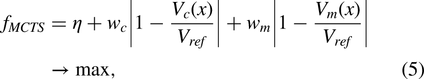
Flowchart of the MCTS.
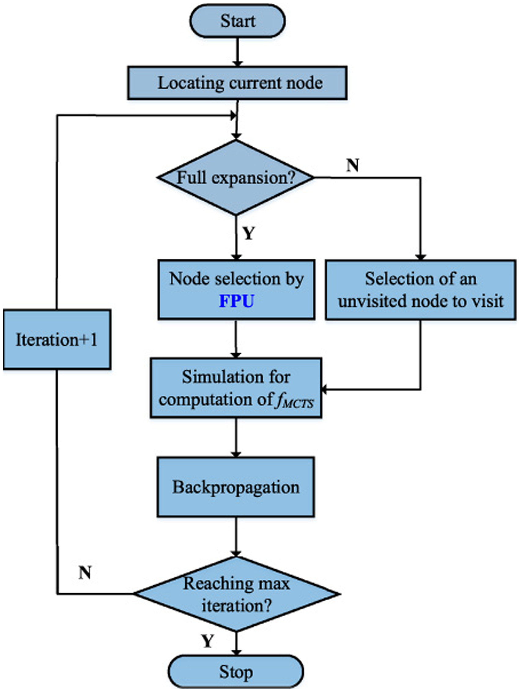
After determining the explicit formula of the objective function, the searching procedure can be carried out, with the flowchart shown in Figure 6. Once starting, the current node p is located. Then if all its child nodes are visited, or in other words, if p is fully expanded, Selection can be implemented, where the upper confidence bound applied to trees (UCT) is used, satisfying with [19]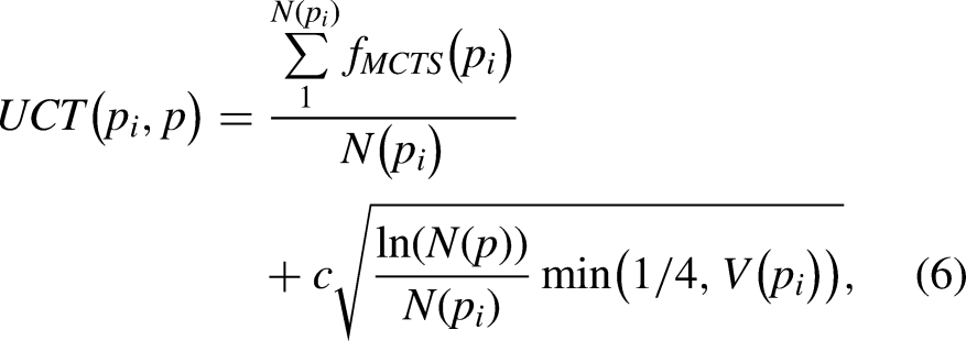
Returning to Figure 6, what follow next is to implement Simulation in MCTS, which is to carry out the simulations of WPT networks in SIMULINK as mentioned in Section 2.1, with specifically selected parameters and configurations, and return results of f MCTS (p i ). Then along with this value and the visited numbers, the information on the traversed nodes from p i to the root can be updated, that is, Backpropagation is implemented. When the number of searching times reaches the maximum value, it terminates, and the best ever solution can be found afterwards, through the searching results.
Let us clarify the design variables which affect the performance of transfer efficiency first. Circuit topology is considered to be the pivotal factor that significantly impact the efficiency. In terms of circuit topology, at the primary and secondary side of the circuit, we can combine S topology, LCL topology, or LCCL topology in any configuration, resulting in five distinct compensation networks, among which the best one will be selected after searching. The five networks, or candidates for topologies, are shown in Figure 7. Each network is labelled as T j , j = 1,2, …, 5.
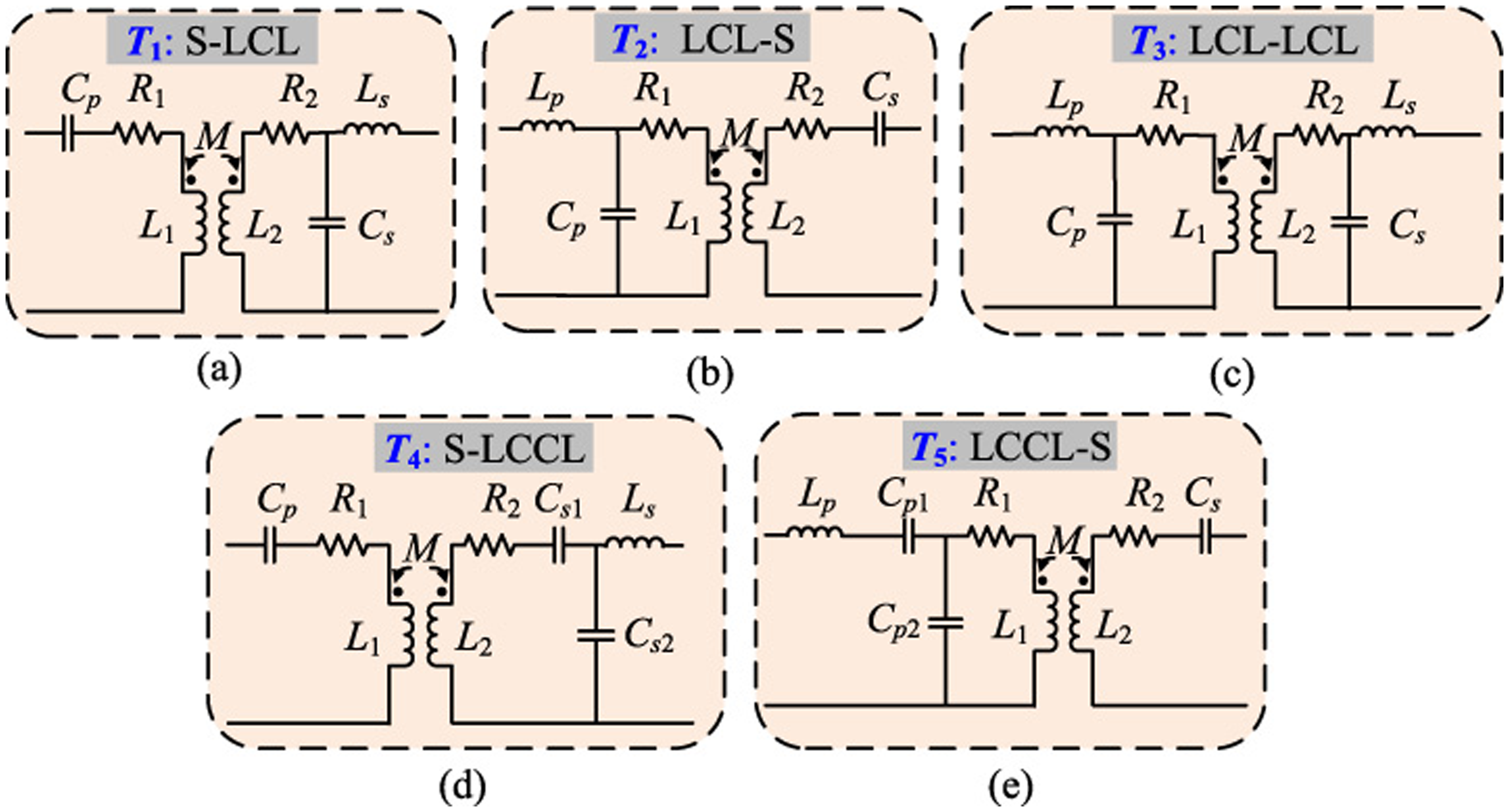
Candidates of topologies T. (a) T1: S-LCL. (b) T2: LCL-S. (c) T3: LCL-LCL. (d) T4: S-LCCL. (e) T5: LCCL-S.
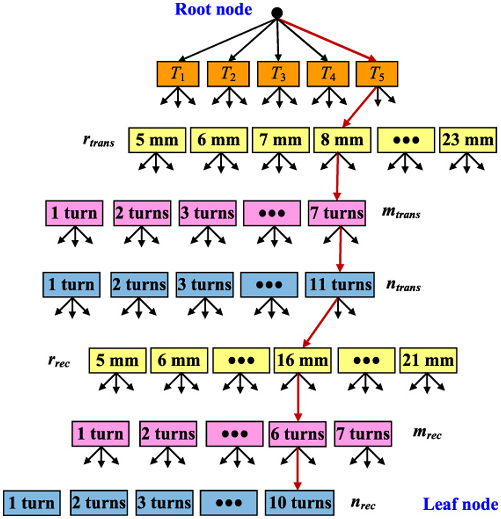
MCT and the path of the best solution.
Apart from the circuit topology, geometric structures of the transmitting and the receiving coils are also key factors on the performance of WPT systems. In this paper, considering electromagnetic characteristics, dimension, and assembly concerns of coils, special attention is given on the radius length of the core, designated by r, the vertical number of turns with respect to coils, labelled as m, and the horizontal turns n, in RZ plane for the axisymmetric coordinates, as shown in Figure 4(a). Since these variables for both the transmitting and receiving coils need to be considered simultaneously, and for the purpose of distinction, in this paper, we use subscript ‘trans’ to denote the corresponding variables associated with the transmitting coil, while subscript ‘rec’ represents those of receiving coil. In conclusion, variables can be written in the 7-dimensional vector form
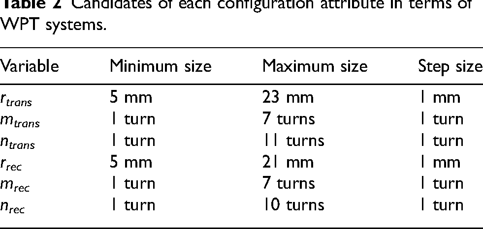
Candidates of each configuration attribute in terms of WPT systems.
After finishing searching, the best design of the WPT system is found at the 101st iteration, with f
MCTS
= 0.945. The detailed settings of the system are
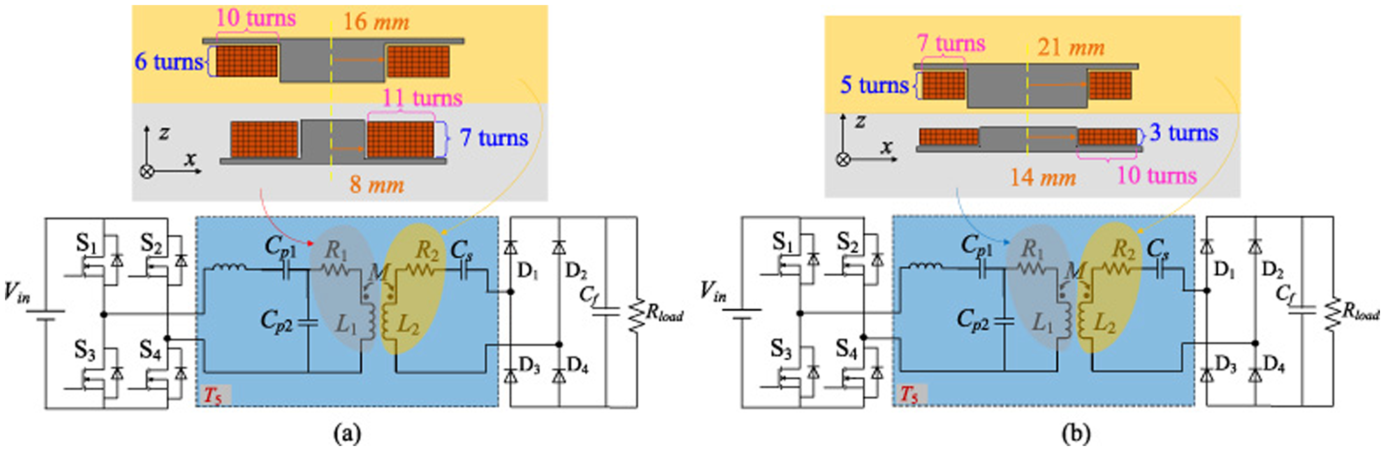
Optimal solutions after searching. (a) The 1st best solution. (b) The 2nd best solution.
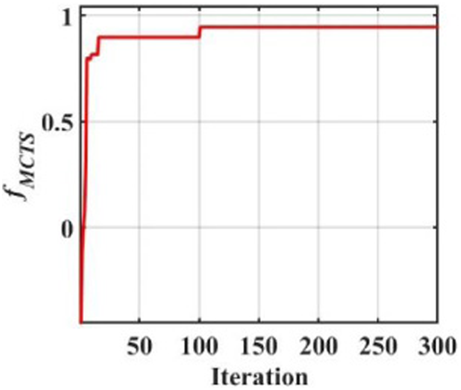
Convergency history.
From the convergence curve Figure 10, we can observe that prior to the 101st epoch which is the best solution, the best-recorded value remained consistent with the results of the 16th iteration, with f
MCTS
= 0.897. The detailed settings of the system are
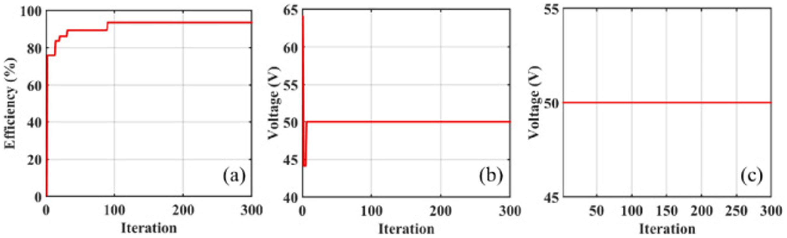
Convergency history of criteria. (a) Efficiency. (b) Output voltage for coaxial alignment. (c) Output voltage for misalignment.
Additionally, from Figure 7 and Table 2, it can be known that the freedom degree of the optimization problem is 8,704,850. However, with using MCTS with just 300 iterations, the relatively satisfactory optimization result can be obtained, indicating the effectiveness of MCTS as an optimization method.
Furthermore, assuming that optimal designs, or best results, are defined to be within a range, then the figure of the occurred best results with the increasing number of searching iterations can be obtained, as shown in Figure 12. Specifically, if the best results are defined as configurations with f MCTS exceeding a certain constant q when a single search iteration is finished and f MCTS is obtained over the threshold q, this search is considered to have achieved the best result. In this study, q = 0.6, 0.7, 0.8, and 0.9 are selected for observation. Additionally, for demonstrating the advantage of FPU Selection policy over UCB1, the obtained best results by UCB1 are also given.
As can be observed easily in Figure 12, no matter which quantity q is set to be, the number of occurred best results by FPU are larger than the corresponding ones by UCB1. It is reasonable, since Expansion is exploration in fact, instead of the exploitation. And at the same time, when initiating searching, the number of visits is low, leading to large value of the exploration term when using UCB1. Therefore, during the early stages of the searches, the heuristics of MCTS with using UCB1 policy are not effectively utilized. This also leads to the low occurrence of best results at various stages of the searches. At the same time, the frequent occurrence of best results by MCTS utilizing FPU policy also indicates that with limited times or a restricted number of searching iterations, there are more opportunities to achieve the optimal solution.
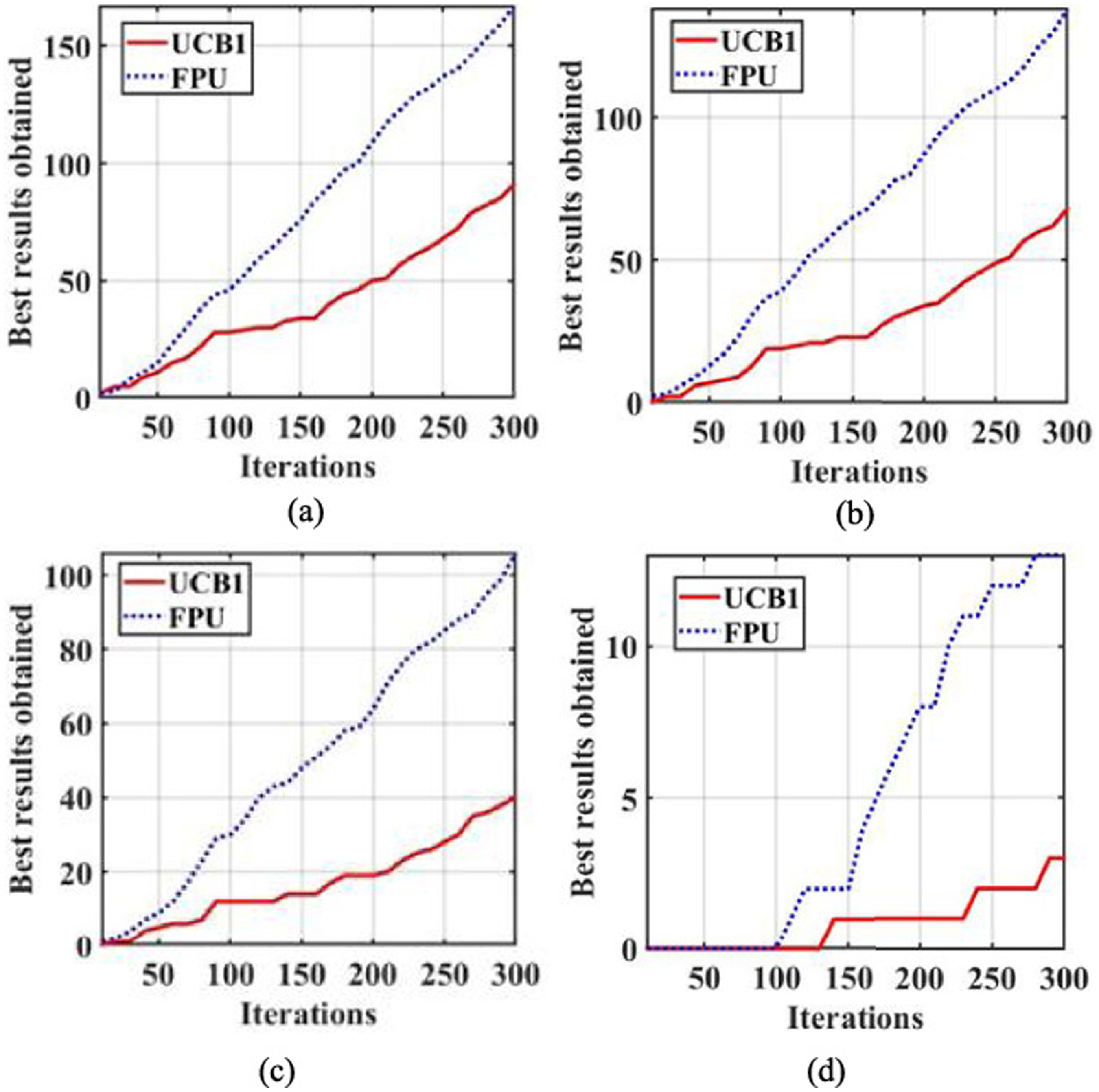
Number of occurred best results with increasing searching times. (a) q = 0.6. (b) q = 0.7. (c) q = 0.8. (d) q = 0.9.
In this paper, a WPT system is designed using MCTS, resulting in obtaining a WPT system with excellent performance on the high transfer efficiency for the cases of coaxial alignment and misalignment between transmitting and receiving coils. At the same time, the output voltage of the systems can be ascertained after optimization. Different from the conventional optimization problems utilizing MCTS based on UCB1 policy for Selection, this study provides an insight into MCTS applying the improved Selection FPU for optimization problems. After validation, this study indicates that the use of the FPU mechanism can effectively leverage the exploitation of the MCTS, particularly when the number of search iterations is limited. This implies that discovering the optimal solution within a finite searching volume is more promising than the UCB1-based MCTS.
Footnotes
Acknowledgements
The authors have no acknowledgments.