






Abstract
This paper proposes a method to reduce torque ripple in axial gap motors by multi objective optimization of permanent magnets (PMs) shape using genetic algorithm (GA). Torque ripple is a problem because it causes vibration and noise. Conventionally, torque ripple has been reduced by quantitatively designing the PMs in the shape of multiplicative wave. However, it is difficult to optimize the objective function only by quantitative evaluation through sensitivity analysis. Therefore, in this study, the functions constituting the PMs interface shape are expressed as a Fourier-based series. The PMs is optimized by optimizing combination of their coefficients with GA. As a result, the proposed model is almost equal to the average torque of the basic model and the torque ripple is significantly reduced. Furthermore, fillets are applied and the effect on each characteristic is verified.
Introduction
In recent years, motors are indispensable in a wide range of fields, such as industrial machinery and electric vehicles. In particular, the number of motors installed in automotive applications continues to increase due to the spread of electric vehicles as well as the use of electric cooling pumps and air-cooling fans. These trends create space constraints due to the increase in the number of automotive components, and one effective solution is to make thinner motors [1]. Currently, PMSMs are widely used and the most common motor is the radial gap motor, however the reduction in torque due to thinner motors is a major problem. In addition, torque ripple is also a major problem, causing noise and vibration, as well as deteriorating the accuracy of position and speed control [2]. To address the above issues, the authors propose the axial gap motor that achieves both thinness and high output and a method to reduce torque ripple.
Unlike radial gap motors, axial gap motor has a gap surface in axial direction and rotor rotates facing stator. When motor is made thinner, air gap can be secured compared to that of radial gap motor, and higher torque can be expected in a flat structure [3,4]. On the other hand, the authors have conducted optimal design of motors for torque ripple and cogging torque reduction [5,6]. Recently, optimal design of motors with optimization methods such as genetic algorithm (GA) has become mainstream [7–11]. However, most optimization by GA in axial motors is based on design variables such as permanent magnets (PMs) width, inner and outer diameters of PMs [10,11].
In this study, the optimal design of axial gap motor for torque ripple reduction is carried out using GA and numerical analysis of electromagnetic fields with 3D-FEM. In this paper, the PM interface shape is expressed as a sum of multiple trigonometric functions, and the combination optimization of each coefficient part by GA is performed to optimize the PM interface shape using three evaluation items which are average torque, torque ripple, and cogging torque.
Proposed motor
Single rotor, single stator 8-pole/12-slot axial gap motor is analyzed with JMAG’s 3D-FEM. Mesh model of the proposed motor is shown in Fig. 1. Table 1 shows the analysis specifications. The stator consists of a disk-shaped yoke and an iron core on which windings are wound. The rotor consists of a disk-shaped yoke and 8 PMs magnetized in the axial direction. The PMs adjacent to each other in the circumferential direction have alternating poles. As shown in Fig. 1, the concentrated winding motor applied in this study is designed with a quarter model considering structural periodicity. Ideal state is considered, and the analysis is performed with 3-phase sinusoidal current.
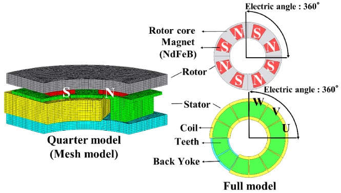
Structure of axial gap motor.
Specification
The main causes of torque ripple are cogging torque and spatial harmonics of flux and inductance. Therefore, torque ripple reduction can be expected in terms of cogging torque reduction. Cogging torque is produced because of interaction between the PMs and the stator slot. The magnetic energy between the gaps E (𝜃) varies with the rotation angle 𝜃, which means relative position of the magnetic poles and coil grooves. The cogging torque T
cog
(𝜃) occurs in the direction where E (𝜃) becomes smaller, as shown in the following relation [12,13].
Equation (1) shows that cogging torque is generated by variation of E (𝜃) due to a change in the magnetic path of field magnetic flux when rotor position changes. Therefore, to reduce the cogging torque, amount of variation in E (𝜃) due to rotor rotation, i.e., relative position change of the rotor to the stator iron core, should be suppressed.
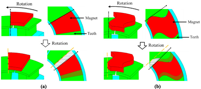
PM in the shape of multiplicative wave. (a) Conventional PM. (b) Proposed PM.
Based on the above, as shown in Fig. 2, cogging torque can be reduced by designing the PMs shape in a multiplied wave shape to suppress the positional change of the rotor relative to the stator core during rotation. The authors have confirmed that this method is sufficiently effective in reducing torque ripple as well as cogging torque [5,6].
Three objective functions are average torque T
ave
, cogging torque T
cog
and torque ripple T
rip
. T
ave
is average value of torque in steady state. T
cog
and T
rip
are given by
Genetic manipulations such as selection and crossover by GA were performed according to JMAG Designer Ver. 20.1. The design specifications of GA are shown in Table 2.
Analysis conditions
Analysis conditions
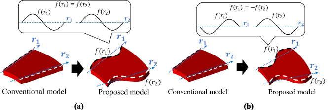
Method of mechanical design. (a) Asymmetrical model. (b) Symmetrical model.
In this paper, the PMs shape is designed as shown in Fig. 3, following the previous studies described in Section 3. In the optimization of the PMs shape, f(r1) and f(r2), which constitute the PMs interface shape, are set and expressed in Fourier-based series.
In this method, we set the following 5 conditions. First, the volume of the PM is set less than or equal to that of the basic model. Secondly, the N and S poles have the same shape. Thirdly, we define f (r1) = f (r2) or f (r1) = −f (r2) and perform two different optimizations. Fourthly, the DC component a0∕2 in Eq. (4) contributes to the parallel shift of both functions, resulting in only a circumferential rotation of each PM. Therefore, a0∕2 is set to 0. Finally, 12 design variables are defined with a n , b n , p n , q n (1 ≤ n ≤ 3) by setting s = 1 and t = 3. However, the increase in the design variable a n , b n , which contribute to the amplitude part, causes problems with increased analysis time due to the increased number of individuals. Furthermore, considering that an increase in the parameters p n , q n , which contribute to the frequency part, results in a complex model that is difficult to manufacture, the design variables are shown in Table 3.
In this study, the PMs shape is optimized by GA with the objective function of maximizing the average torque and minimizing the torque ripple. For each optimization, the individual with at least 95% of the average torque of the basic model is selected. Among these individuals, the one with the smallest torque ripple is selected as the optimal model for each optimization.
Analysis conditions
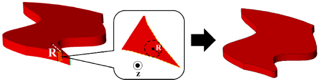
Filleted PMs.
For each of the optimal models selected in the previous section, the PMs shape that can be manufactured is examined. As shown in Fig. 4, stress concentrates in the corner of PMs and may cause damage during manufacturing. Hence, fillet with radius R is applied near the corner as shown in Fig. 4, and the effect on each characteristic is examined.
Simulation result
Analysis results with GA
The distributions pareto optimal solution in the average torque and torque ripple from 0th generation to 25th generation are shown in Fig. 5. In this optimization, eight parallel shared memory computing were performed. The optimization with asymmetric geometry took 480 hours, while the optimization with symmetric one took 575 hours (Processor: 18-core Intel® Core TM i9-10980XE CPU 3.00 GHz 32 GB). In each optimization, the optimal models are shown in Fig. 6. The values of a n , b n , p n , q n (1 ≤ n ≤ 3) that constitute each shape are shown in Table 4. Each characteristic of the selected model is shown in Table 5. As a result, in the case of asymmetric optimal model, the average torque was reduced by 4.7%, but torque ripple was reduced by 87.9% and the cogging torque by 59.6% compared to the basic model. On the other hand, in the case of symmetric one, the average torque was reduced by 5.0%, but the torque ripple was reduced by 88.6% and the cogging torque by 62.0%.
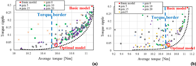
Distribution of pareto optimal solution. (a) Asymmetrical model. (b) Symmetrical model.
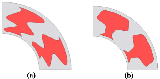
Optimal model. (a) Asymmetrical model. (b) Symmetrical model.
Analysis conditions
Characteristics of each model
Figure 7 shows the magnetic flux density distribution for the basic model and the selected optimal model. These are the magnetic flux density distributions at the maximum cogging torque in the de-energized state. In basic model, asymmetry of the magnetic flux density in the radial direction is observed in some parts. Therefore, an unbalance of the magnetic flux density distribution occurs in the entire motor, which lead to an increase in cogging torque. On the other hand, the magnetic flux density distribution of the optimal model with asymmetrical geometry is more balanced compared to the basic model. However, it shows that the asymmetry of the magnet shape causes an imbalance in the magnetic flux density in the radial direction. In contrast, the magnetic flux density distribution of the optimal model with symmetrical geometry remains symmetrical in the radial direction and is stable. Therefore, the cogging of both models is smaller than that of the basic model. In addition, the cogging torque is smaller for the model with symmetrical geometry compared to the model with asymmetrical geometry.
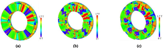
Magnetic flux density. (a) Basic model. (b) Asymmetrical model. (c) Symmetrical model.
Figure 8 shows the results for each characteristic filleted. Regarding Fig. 8(a), the bar and line plots show the average torque and PM’s amount for the fillet R, respectively. The average torque, torque ripple and cogging torque are p.u. values based on each characteristic value of the basic model. When filleted, the amount of PM is reduced, but the average torque of each model only shows a decrease of about 1 ∼ 2%, which is not considered to be a significant effect. Similarly, regarding cogging torque and torque ripple, each model shows a decreasing trend and no significant effect. Therefore, there is almost no effect of fillets on any of the characteristic.
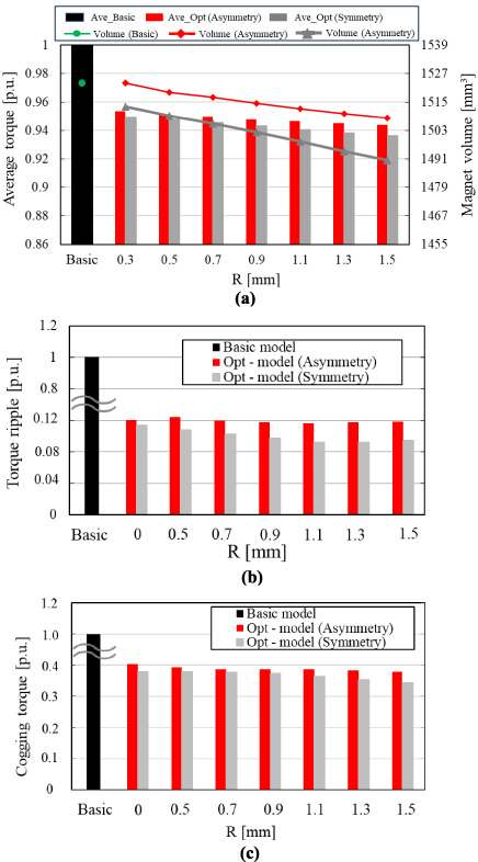
Each p.u. value with fillet. (a) R - average torque. (b) R - torque ripple. (c) R - cogging torque.
In this paper, PMs optimization of an axial gap motor using 3D-FEM and GA was performed to study low torque ripple. As a result, torque ripple was significantly reduced while almost maintaining average torque. Therefore, it was confirmed that this method is effective in reducing torque ripple. In the future, we plan to propose a highly efficient motor structure by optimizing the shape of the iron core. In addition, we plan to verify the validity of our method by verifying the selected model on actual machines.
Footnotes
Acknowledgements
The authors have no acknowledgments.