
Abstract
Traditional dual active bridge converters use transformer leakage inductance instead of energy storage inductors for magnetic integration, but this method cannot accurately control the leakage inductance. A phase shift control dual active bridge converter base on integrated magnetics is proposed, in which one transformer and one inductor are integrated in an EE core. The size of the inductance can be accurately controlled. The transformer and the inductor are decoupled and integrated so that the two operating states do not affect each other. The weight and volume of the magnetic elements are reduced accordingly. The finite element analysis and magnetic circuit simulation of the integrated magnetics are carried out. Finally, the integrated magnetics are designed and applied to the 600W prototype to realize bidirectional power transmission and a weight reduction is about 36.24% and a volume reduction is about 35.84%. The correctness of the design is verified by experimental results.
Introduction
Power electronics technology is developing rapidly, DC/DC converters are used more and more widely in various fields. Nowadays, the converter are moving toward high power density and high frequency. However, according to statistics, magnetic components (including transformers, inductors) generally account for 30% to 40% of the weight of the converter, accounting for about 20% to 30% of the volume of the converter [1]. Therefore, the magnetic element is a major factor limiting the efficiency and power density of the converter. Integrated magnetics technology emerges as the times require, which can effectively reduce the size, cost and loss of magnetic core.
DAB converter.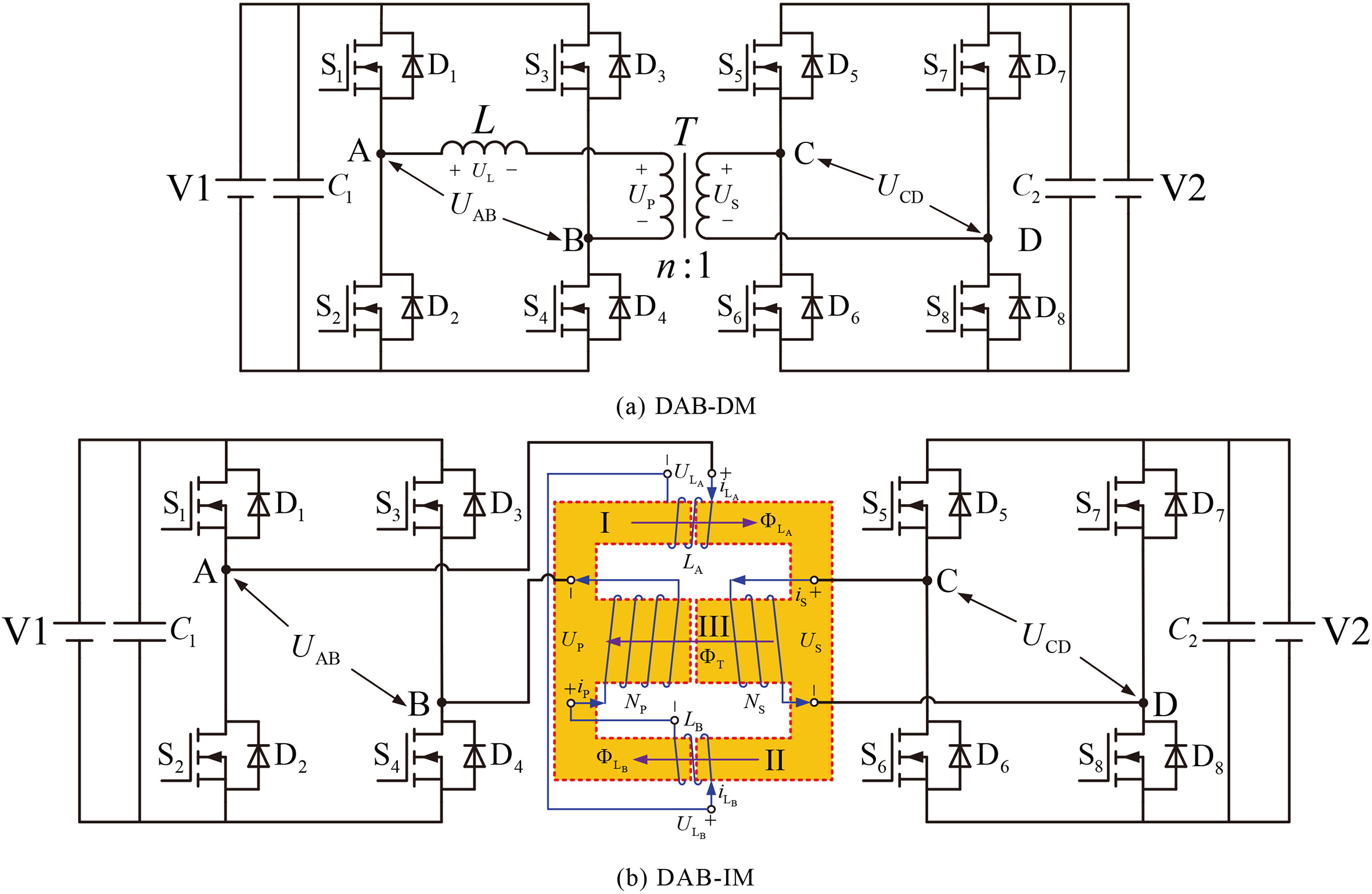
Dual active bridge (hereinafter referred to as DAB) has low voltage and current stress, which is suitable for high power applications and can realize soft switching of all devices after adding a clamp circuit. The advantage of DAB is that the control method is simple, and the power flow direction and size can be controlled under phase shift control. However, there are also some shortcomings: the complicated structure increases the product volume and design cost; the energy transfer of the transformer leakage inductance leads to a larger circulation energy [2]. Therefore, IM technology is introduced. The size of converter can be reduced by IM technology, thereby it can improve the power density and the efficiency of the converter.
Reference [3] uses a magnetic core to realize one transformer and three inductors of the ZVS full-bridge converter. All primary side H bridge switches are capable of zero voltage switching and the secondary side H bridge rectifier achieves a zero current switching state over the entire load range. However, the bidirectional transmission of energy is not achieved. Reference [4] proposes an optimal which combines the advantages of phase-shift with duty cycle modulation and traditional pure phase shift modulation. In this control method, soft switching in full power range and ensuring the maximum transmission power can be realized at the same time. But the IM is not realized. In summary, this paper proposes the IM of DAB, which realizes the increase of power density and the bidirectional transmission of energy.
Traditionally, the magnetic integration of DAB is to adjust the distance between the primary and secondary windings of the transformer to generate leakage inductance to achieve the energy storage inductance. The size of the energy storage inductor has a great impact on the energy transfer of the converter. Therefore, this paper presents a DAB magnetic integration with controllable inductance. The most typical control for DAB converters is Single-Phase-Shift (SPS) control, which changes the magnitude and direction of transmission power by adjusting the phase shift angle between the H-bridges on both sides of the converter [4]. The control methods of DAB include Dual-Phase-Shift (DPS) control [5, 6] and Triple-Phase-Shift (TPS) control [7, 8], which can improve the efficiency of DAB transmission. This paper mainly analyzes the operation of the IM in the SPS control mode. Figure 1a is the DAB discrete magnetics (DM), Fig. 1b is the DAB integrated magnetics (IM).
Analysis of DAB electric circuit-magnetic circuit coupling
Integrated magnetics.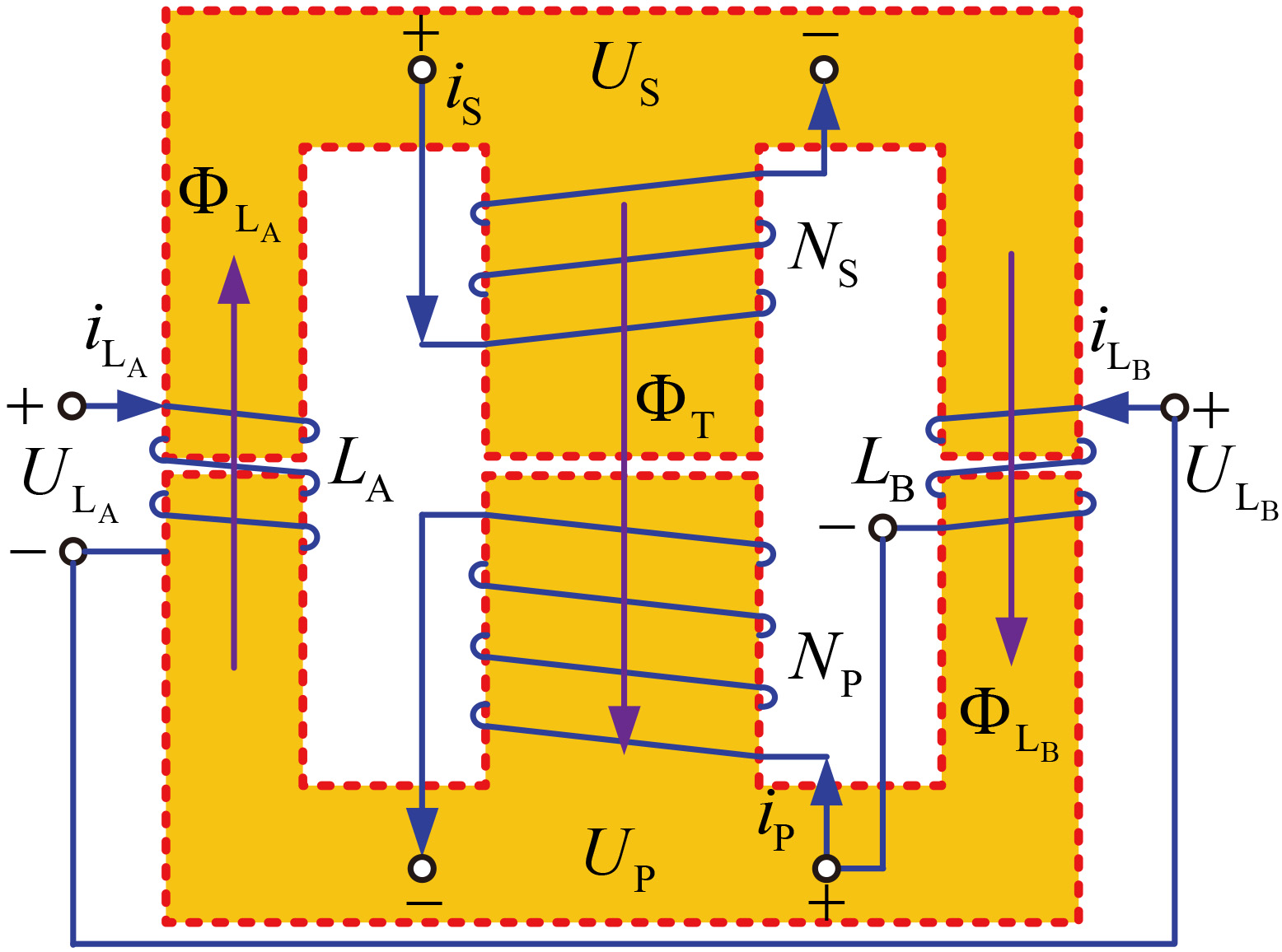
Equivalent magnetic circuit of IM.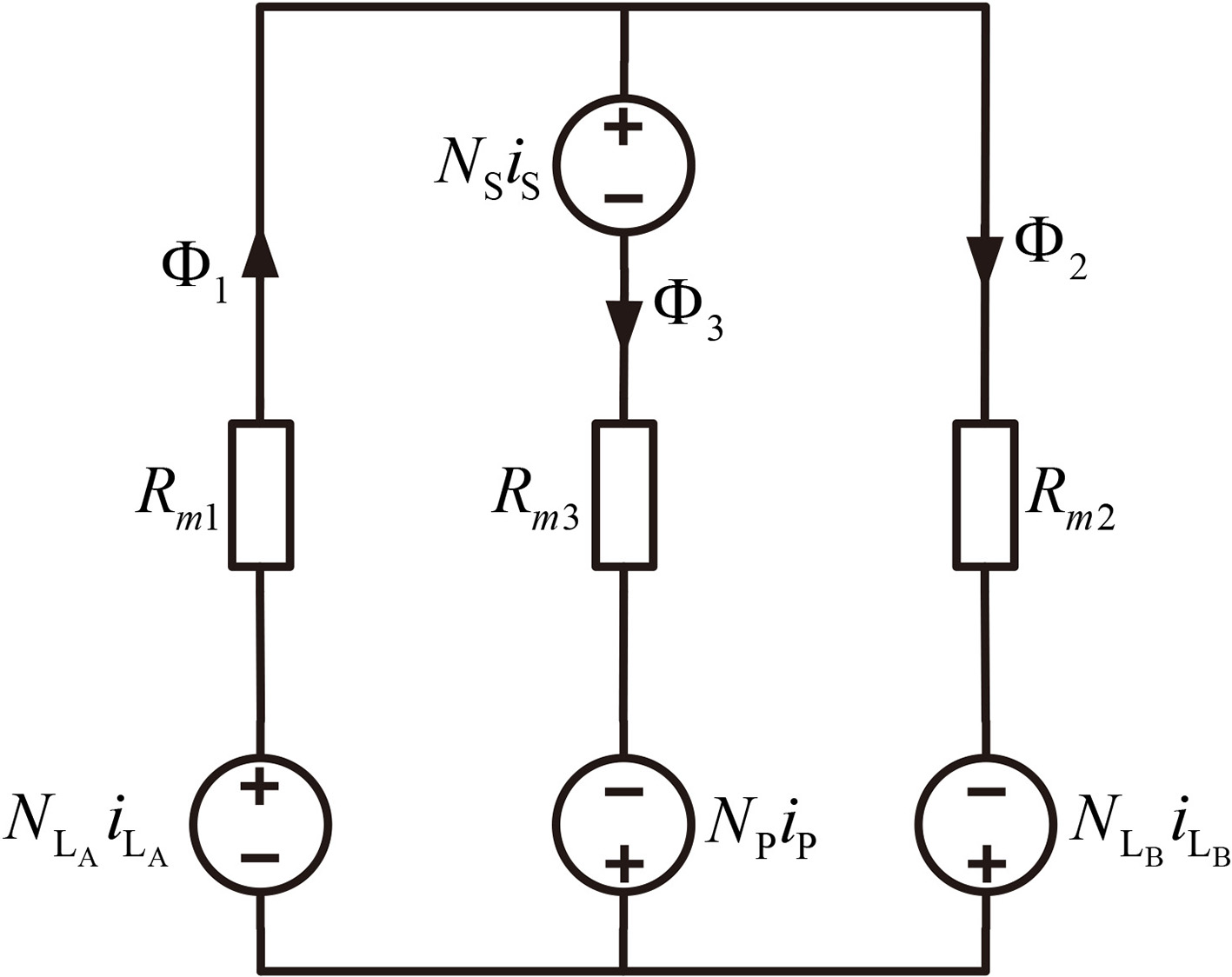
Figure 2 is the schematic diagram of IM,
To facilitate the design of EE cores, the air gap is opened at the same time in three magnetic columns, in which the cross-sectional area of the middle column is twice as large as that of the side column, so it can be obtained:
According to the equivalent magnetic circuit of IM as shown in Fig. 3,
Then the flux
Because the inductor voltage
Substituting Eqs (2) and (3) into Eq. (4), the voltage and current relationship of the magnetic element can be written as:
The parameters of Eq. (5) are shown in Eq. (6):
Then the coupling coefficient can be simplified as follows:
In Eq. (7),
Assuming
When the coupling coefficient of the inductor and the transformer
DAB-IM operation waveforms under SPS control.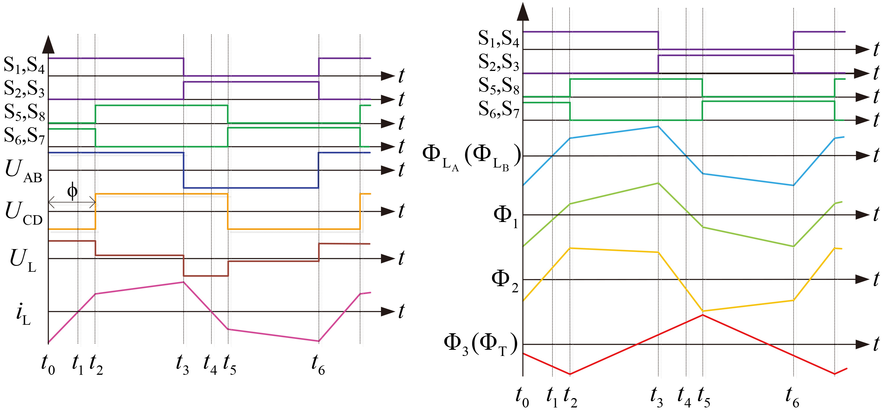
DAB-IM operation modals.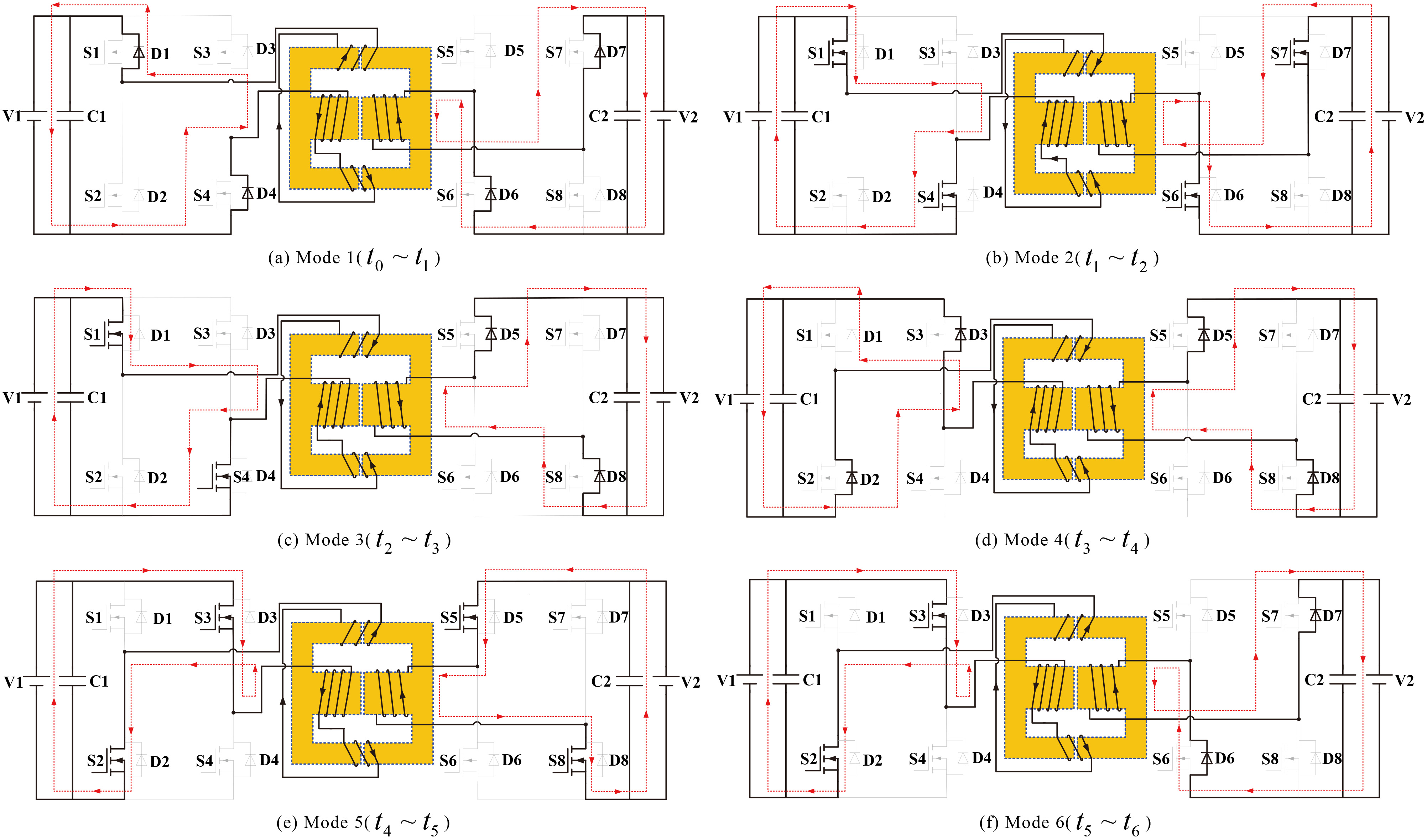
The DAB-IM AC magnetic circuit [10] is shown in Fig. 6, in which
Equivalent AC magnetic circuit.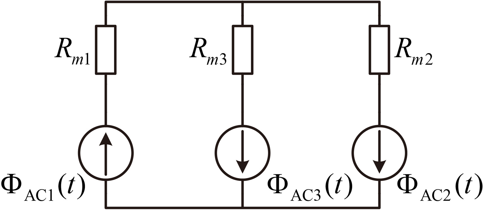
Mode 1 (
Mode 2 (
Mode 3 (
Mode 4 (
Mode 5 (
Mode 6 (
From the above analysis, the internal magnetic flux waveform of the integrated magnetics piece can be obtained, as shown in Fig. 4. The principle of the reverse operation mode is similar to that of the forward operation simply by changing the full bridge phase shift angle of the secondary H side is advanced to the full bridge phase-shifting angle of the primary H side. The magnetic flux analyzed by the internal magnetic flux of the IM core has zero variation in one cycle, which is the same as the DM.
Equivalent DC magnetic circuit.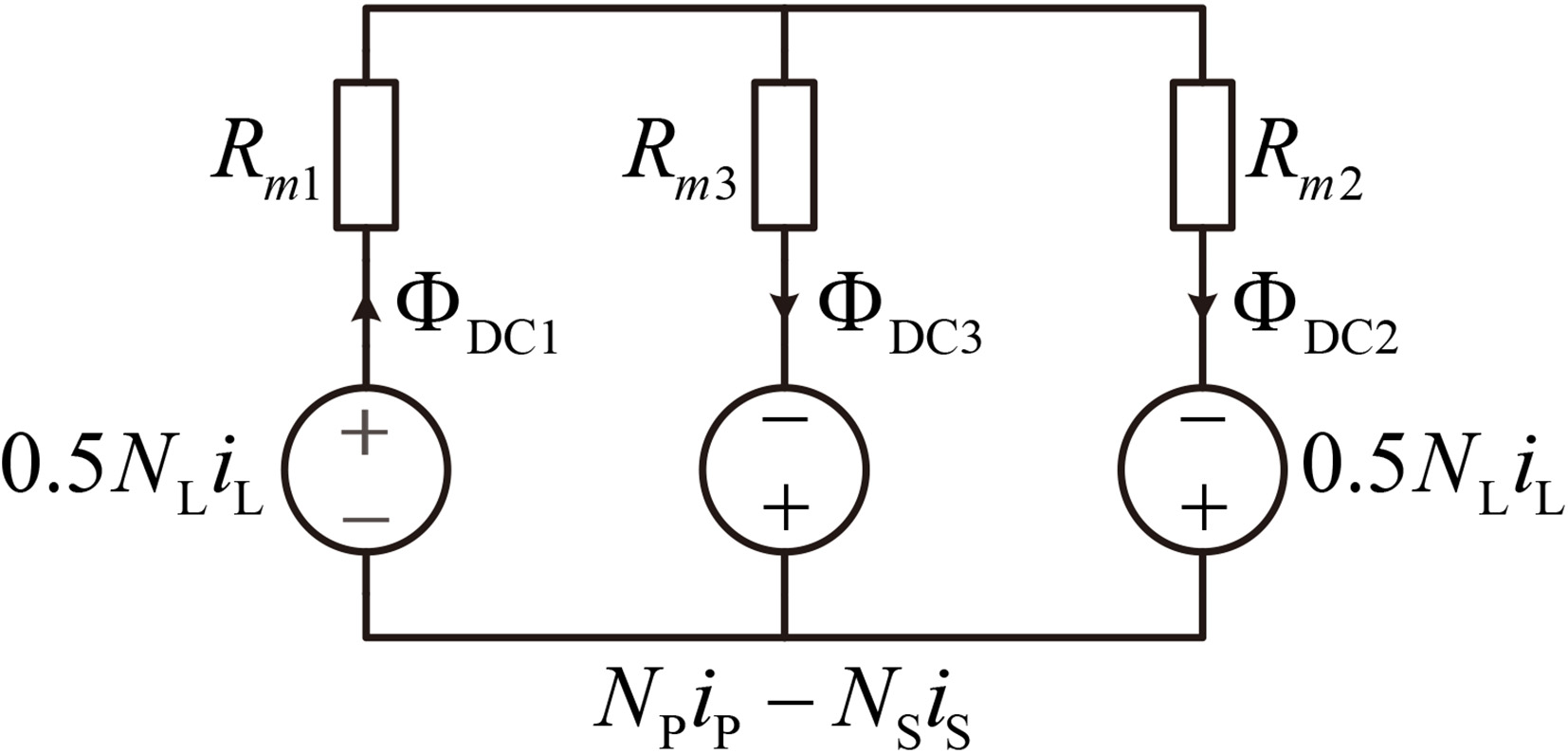
The IM-DAB DC magnetic circuit is shown in Fig. 7. According to Ampere circuital theorem, the DC flux of each magnetic column is determined by the DC ampere turn and reluctance of the winding, so each magnetic column has an equivalent DC voltage source
In Eq. (22),
It can be seen from Eq. (23) that the DC component of the inductor core is
G-C model of inductance/transformer IM.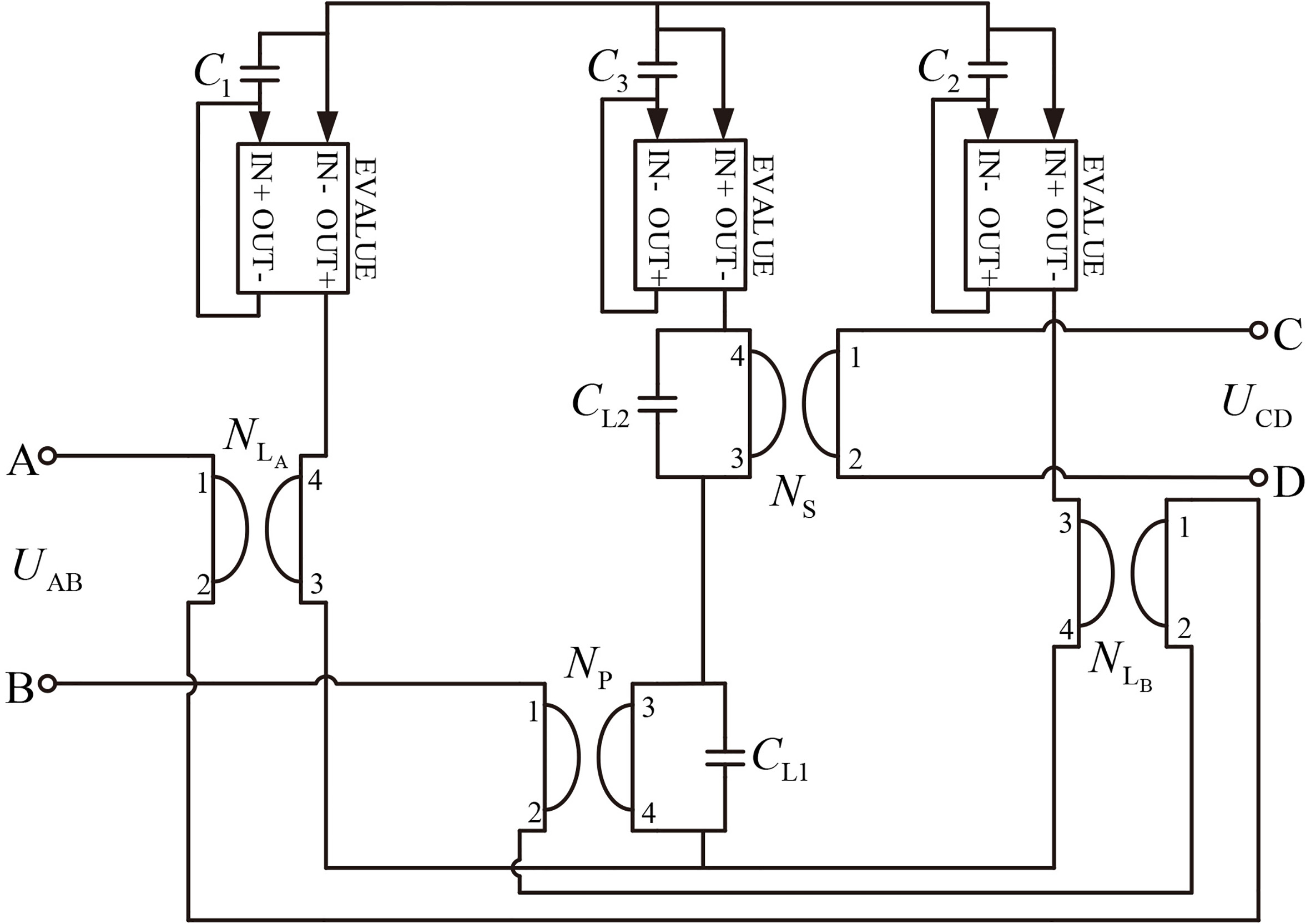
The gyrator-capacitor model has many advantages in simulating magnetic core nonlinearity and circuit-magnetic circuit hybrid simulation. In Fig. 8, the gyrator-capacitor model (hereinafter referred to as G-C model) [12] of DAB-IM is established in Spice software to test the accuracy of the design.
CCVS circuit diagram of G-C model.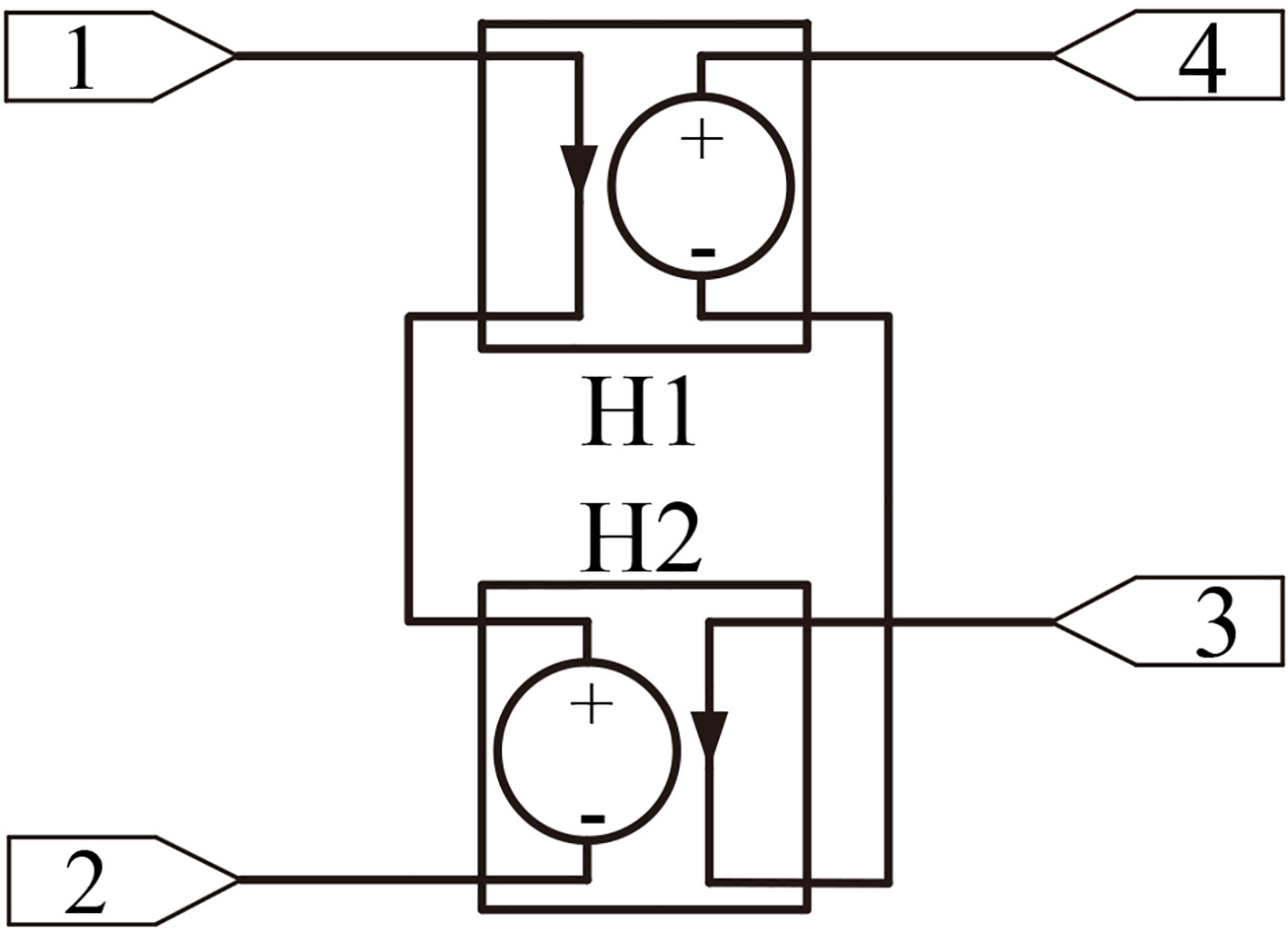
G-C model simulation waveform diagram.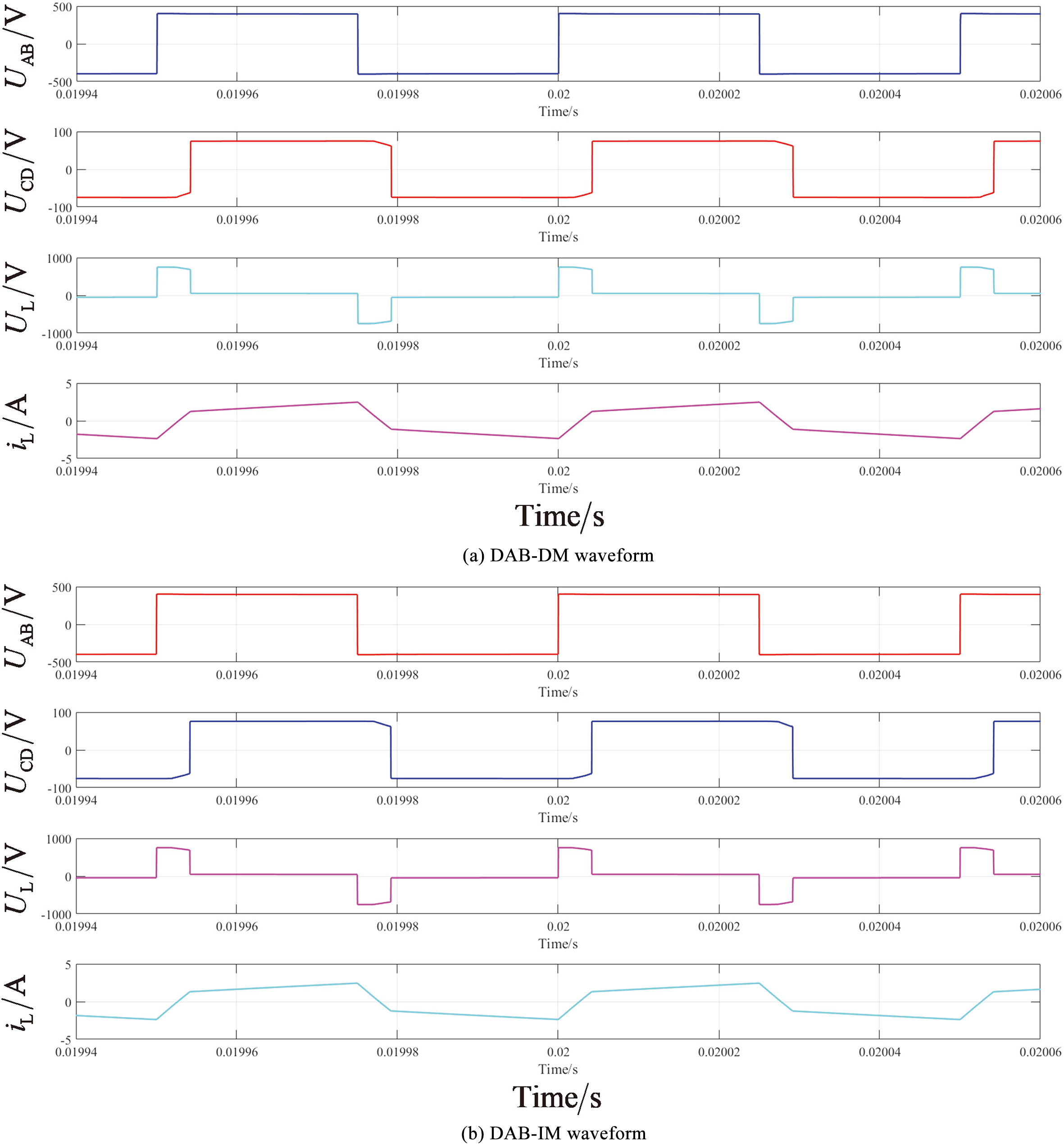
IM prototype parameters
Simulation analysis of gyrator-capacitor model
The above analysis is verified by simulation. Switch tube selects IXFB60N80P, switching frequency is 20 kHz. The transformer ratio is 5:1, and inductance is 860 uH. Input voltage is 400 V, output voltage is 75 V. Figure 10a is a simulation waveform diagram of the DAB discrete magnetics. Figure 10b is a simulation waveform diagram of the DAB integrated magnetics. The simulation results show that the waveforms of
IM electric circuit-magnetic coupling calculation and analysis
Flux density distribution in IM core.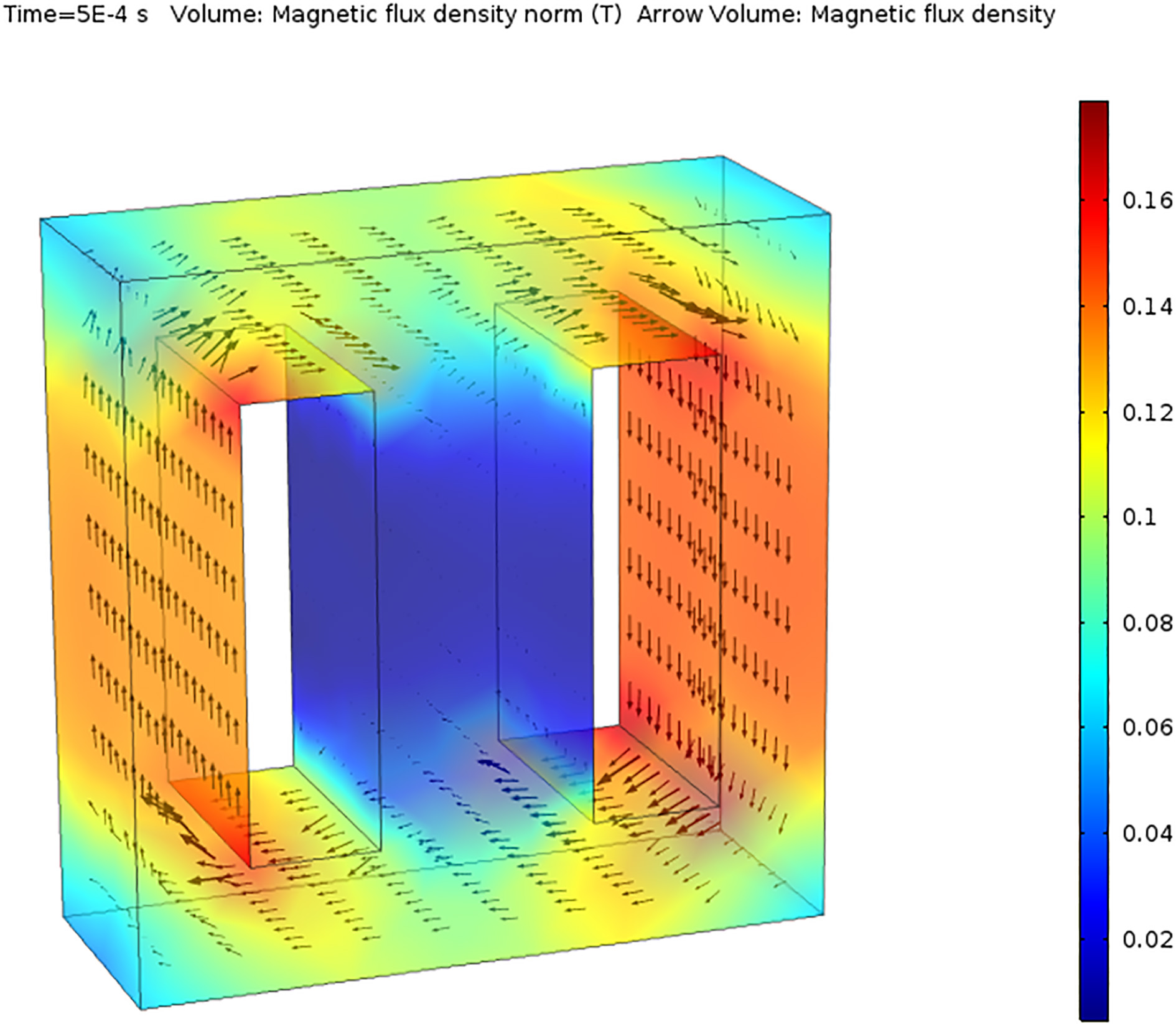
IM core loss density distribution.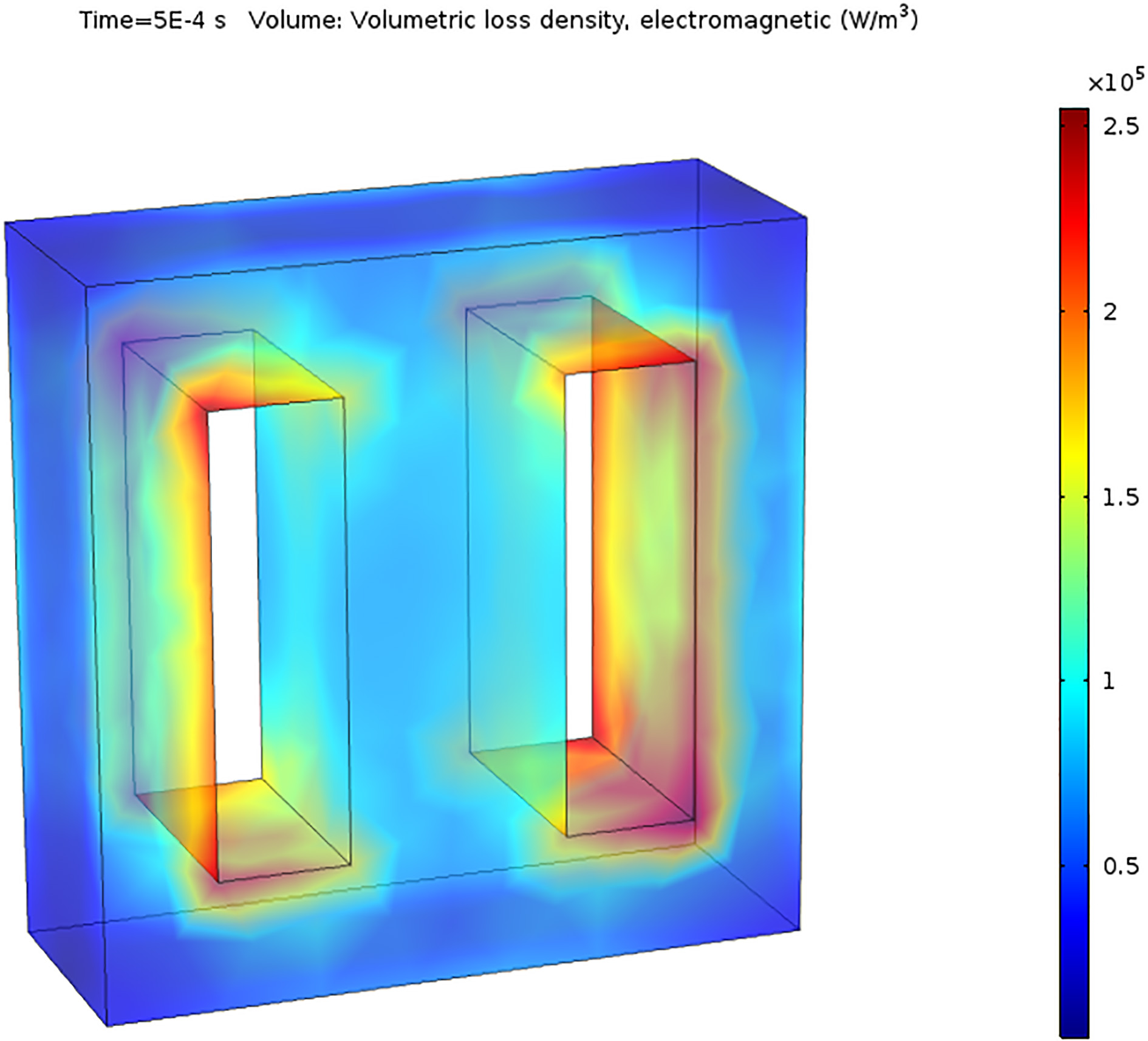
Prototype experimental system.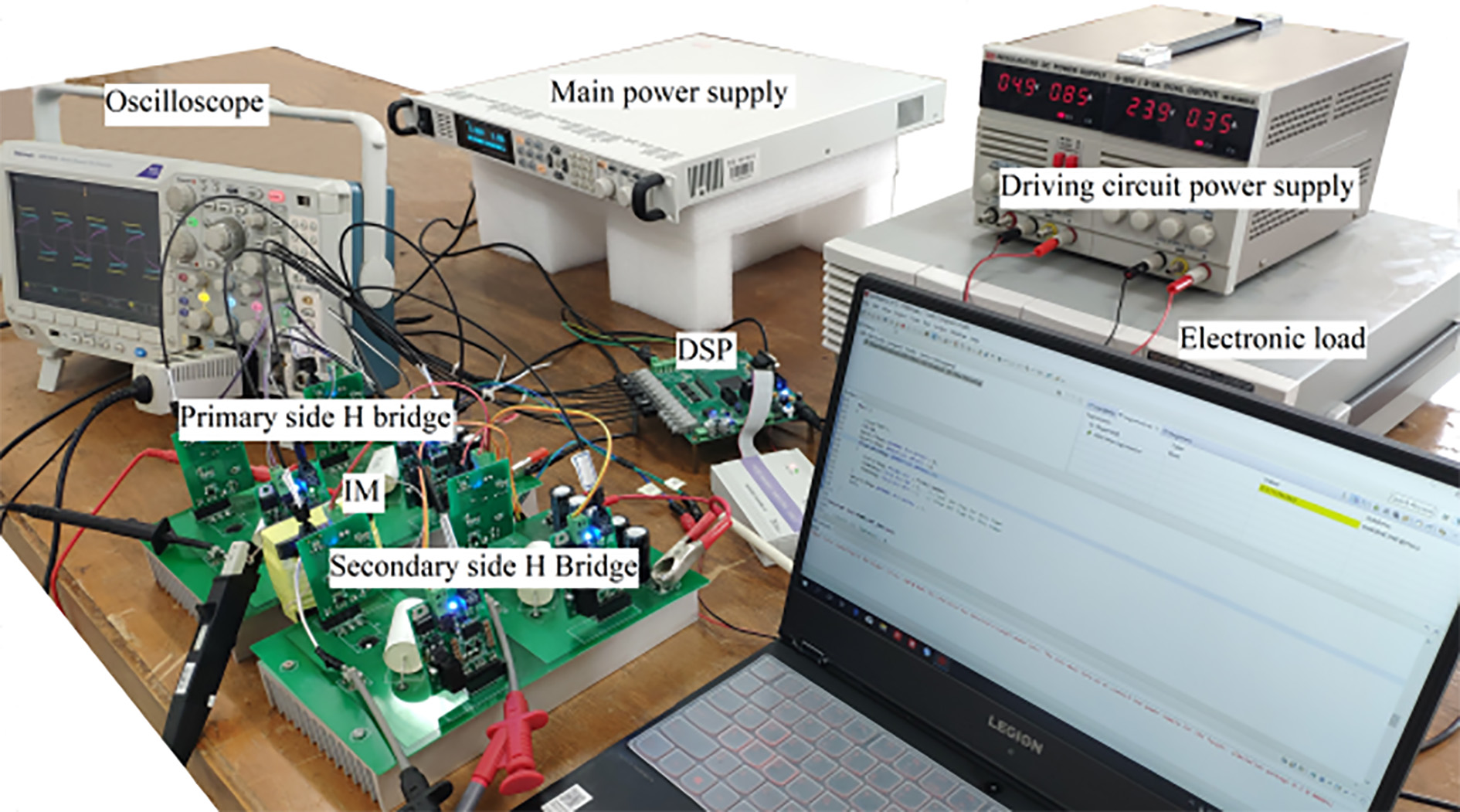
Physical comparison before and after integrated magnetics.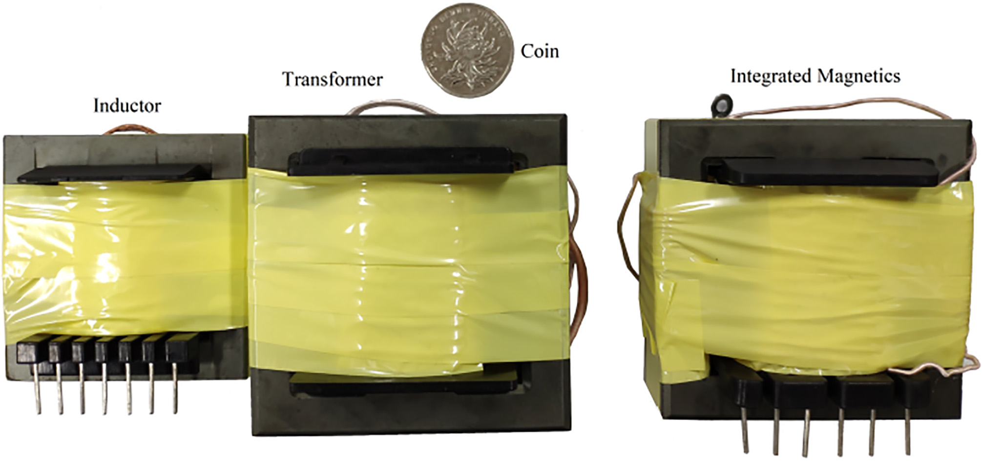
Phase-shifted 30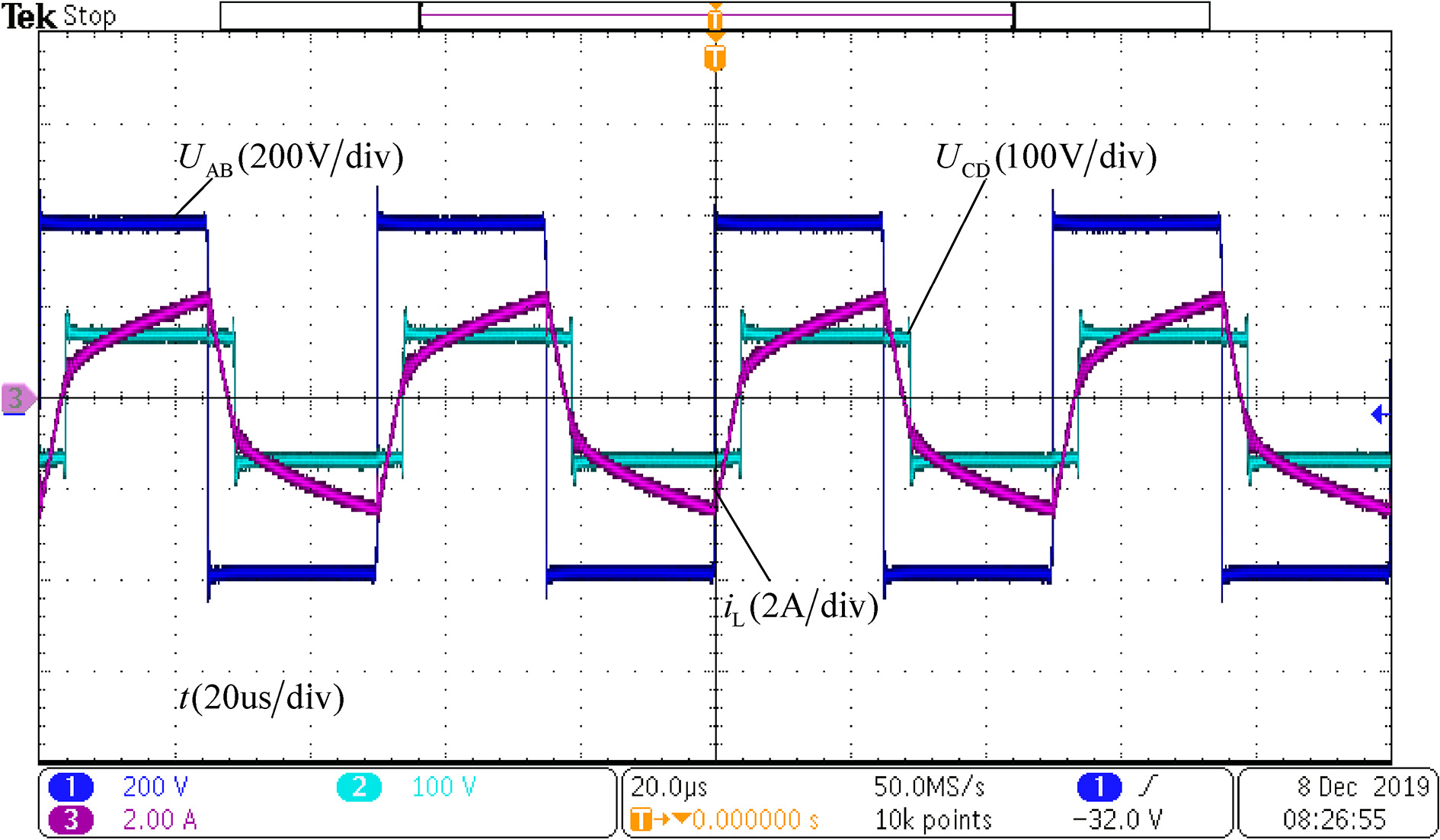
Phase-shifted 60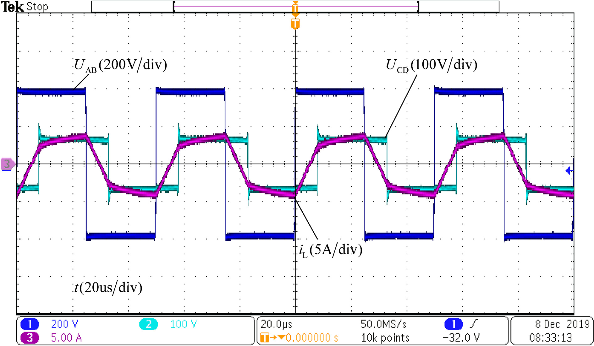
Phase-shifted 90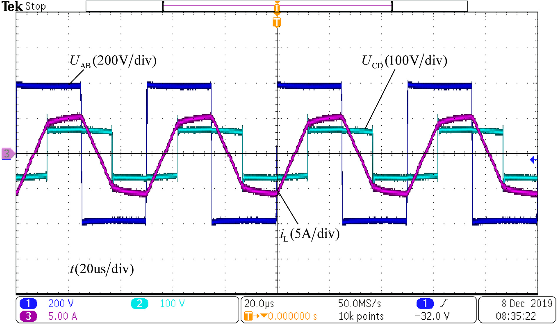
Reverse transmission phase-shifted 30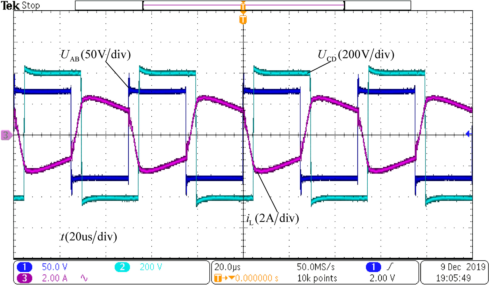
Efficiency comparison between DM and IM. 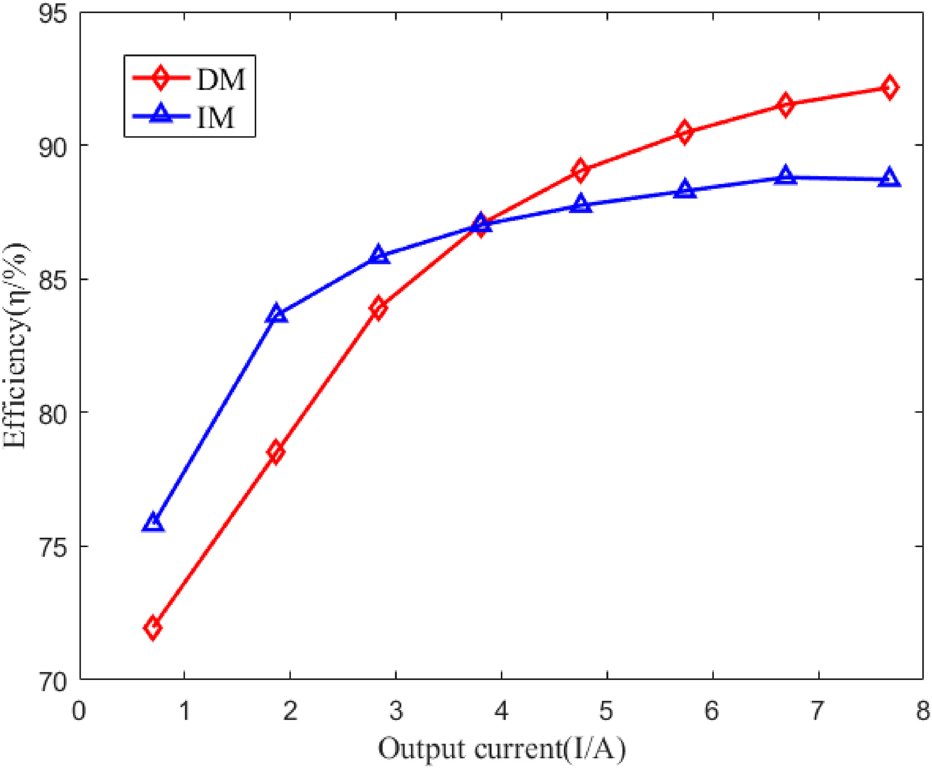
Comparison of output power of IM with different coupling degrees.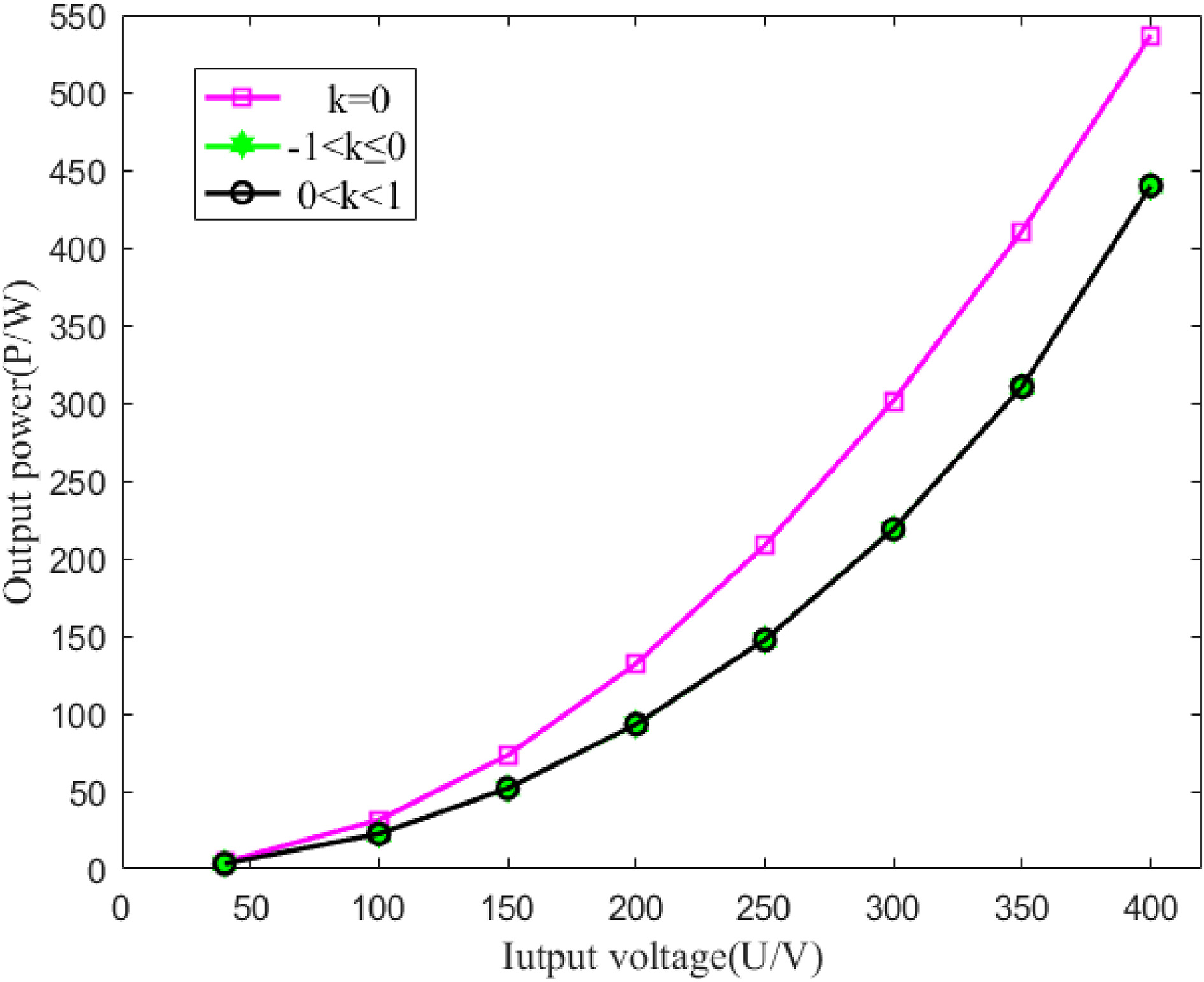
The finite element [14, 15, 16] analysis software is used to establish the IM electric circuit-magnetic field finite element model, so as to verify whether the internal magnetic flux density of the design meets the requirements. Figure 11 shows the flux density distribution of IM core under the control of SPS. Figure 12 shows the loss density distribution of IM core under SPS control. Under the control of SPS, the operating magnetic density of the core is about 0.14 T, and the maximum magnetic density is about 0.18 T, which is far less than the saturation magnetic density of 0.35 T of ferrite. In this case, the core is unsaturated and the loss is low. Therefore, the EE65 core selected under the control of SPS meets the design requirements [17, 18].
A integrated magnetics DAB experimental prototype of 600 W, 400 V input, 75 V/8 A output, and 20 kHz was fabricated to test the previous analysis. The IM parameters are shown in Table 1. Figure 13 is the experimental prototype, Fig. 14 is the physical comparison of the magnetic parts before and after the integrated magnetics. Experiments were carried out on the DAB-IM under the SPS control phase shift angle 30
It can be clearly seen in Fig. 14 that when discrete magnetic parts are used, the design of the inductor core and transformer core are EE65 and EE55 respectively. Integrated magnetics can still use EE65. In this way, the volume and weight of the integrated magnetic core can be reduced by 35.84% and 36.24% respectively. Figures 15–17 are the phase shift waveform of 30
Figure 19 is a comparison of the operating efficiency of DM and IM under the same output current. When the output current is less than 4A, the efficiency of IM is greater than DM, but when the current is greater than 4A, the efficiency of DM is greater than IM. With the increase of the output current [19], the saturation of the integrated magnetics component will increase, which will lead to increased losses and increased temperature, and the decrease of the efficiency. Figure 20 is a comparison of the output power of different coupling degrees under the same input voltage. It can be clearly seen that the output power is maximum when the coupling coefficient
Summary
A new integrated magnetics DAB is proposed. The proposed integration method is used to realize the decoupling integration of DAB inductor and transformer with a EE magnetic core. Compared with the discrete magnetics, the volume and weight of the integrated magnetic core can be reduced by 35.84% and 36.24% respectively. Simulation and experimental results verify the integrated magnetics can realize the bidirectional transmission of DAB power under phase shift control. The advantages of the method proposed in this paper are: (1) The power density of the converter is improved; (2) The energy storage inductance of the converter can be controlled; (3) The bidirectional energy flow of the converter can be realized.
Footnotes
Acknowledgments
Fundings: National Natural Science Foundation of China (51337001), National Natural Science Foundation of China (51777136), Joint Fund of State Key Laboratories of New Energy and Power Systems (LAPS 16017).