
Abstract
Multilevel inverter topologies have been widely used in applications of wide-power range and fault diagnosis of such circuits is becoming more and more important. T-type three-level inverters have advantages in efficiency compared to common neutral-point-clamped inverters. This paper proposes a new diagnosis method of an open-circuit (OC) fault for a T-type three-level inverter. The method is implemented by measuring the phase voltage of the circuit and comparing it with the reference voltage of the circuit to obtain a residual voltage. Firstly, according to the analysis of different current conduction paths of the circuit, the voltage level changes of the circuit bridge voltage and phase voltage in different device open modes are studied. Then, based on the above analysis, a device open-circuit fault diagnosis scheme is proposed based on the residual voltage. Finally, simulation and experimental results show that the proposed method can identify the faulty switch exactly and quickly.
Introduction
Multilevel inverters have been increasingly used in a wide range of power applications. Compared to traditional two-level inverters, multilevel inverters can get more levels, have fewer harmonics, and reduce the voltage stress requirements of the device [1, 2, 3, 4, 5]. However, these advantages are mainly obtained by series or parallel connection of switching devices, which leads to an increase in the number of switching devices in the circuit, thereby reducing the reliability of the entire inverter. As long as one of these switching devices fails, the entire system will fail or even cause serious consequences [6]. Therefore, fault diagnosis research for multi-level inverters is very necessary now.
The topology of multilevel inverters can usually be classified into a neutral-point-clamped type, a cascade type, and a flying-capacitor type. In general, these multi-level inverters are always used in high-power applications, but in order to obtain the advantages of multi-level inverters, applications in small and medium-power are more and more popular [7, 8, 9].
In recent years, a new inverter topology named T-type neutral-point-clamped inverter (TNPC) is proposed [10]. The topology is mainly used in high-efficiency applications such as solar and electric vehicle inverters. The main circuit topology is shown in Fig. 1. This topology is based on the traditional two-level inverter, adding three pairs of bidirectional active switching devices connected to the input voltage midpoint “o”. As shown in Fig. 1,
Schematic of the three-level T-type inverter topology.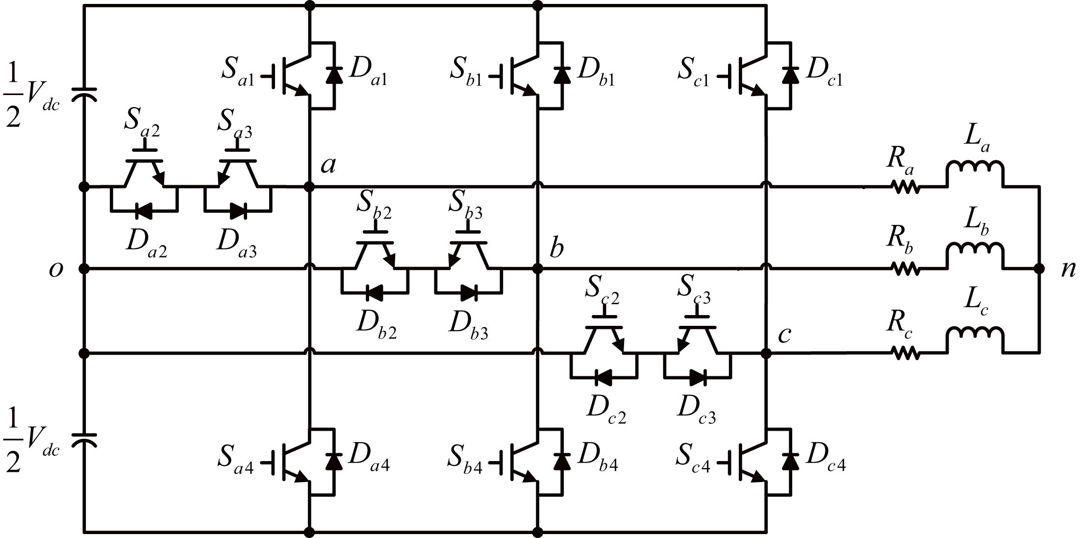
In order to improve the reliability of the circuit system, many fault diagnosis and fault tolerance methods have been proposed for various types of converters [11, 12, 13, 14]. Switching device faults in the converter can be divided into two major categories: short-circuit and open-circuit. Among them, the short-circuit fault will generate a large current in an instant, so it is more difficult to diagnose in practice and the main fault diagnosis methods include adding a fuse or other hardware circuit in the circuit [14]. Relatively, the open-circuit fault has no such serious consequences of short-circuit fault. When an open-circuit fault occurs, the output voltage or current will be distorted. The circuit can still work, but the performance will be reduced, so the current fault diagnosis research of the converter is mainly focus on open-circuit faults [11, 12, 13].
At present, some research results of fault diagnosis for T-type converter have been proposed [15, 16, 17, 18, 19]. In [15, 16] diagnose faulty switching devices by analyzing the average of the phase currents and the midpoint potential of the input voltage. In [17], the phase angle of the input AC voltage when the phase current crossing zero is used to determine the device in which an open-circuit fault has occurred. In [18], the output voltage is converted into a histogram according to a certain algorithm, and then the center of mass is calculated, and the faulty device is judged according to the calculated value. In [19], switching fault of a single-phase T-type inverter is diagnosed by analyzing the level of the output voltage and the corresponding switch state. In the paper [20], the proposed fault diagnosis method is achieved by measuring the bridge voltage and its duration time. An on-line nonintrusive diagnostic method for detecting open-circuit switch faults in T-Type multilevel converters is introduced in [21] and the principle of this method is based on monitoring the abnormal variations of the dc-bus neutral-point current in combination with the existing information on instantaneous switching states and phase currents. However, there are not many research results on the fault diagnosis of the T-type three-level inverter. In addition, some of the proposed methods need to simultaneously detect both voltage and current [15, 16, 17], or two kind of currents in different point [21]. An additional fault diagnosis circuit is needed for each phase of the T-type inverter in the paper [20]. Complex algorithms are required in other fault detecting method [18].
In this paper, a fault diagnosis method focus on open-circuit switching device of a T-type three-level inverter is proposed. The principle of the method is based on phase voltage residual. The output phase voltage of the circuit is detected and compared with the reference phase voltage. The open-circuit faulty device of the circuit is detected and located by analyzing the difference between these two voltages. The second section introduces the simple working principle of the T-type three-level inverter. The third section analyzes the output voltage of the T-type three-level inverter under normal fault working conditions and proposes a method of fault diagnosis. The forth section gives the experimental verification results. A comparison with other proposed methods is given in section five. Finally, the conclusions of the paper are given.
As shown in Fig. 1, the voltage
Switching state, switching command and bridge voltage of T-type three-level inverter
Switching state, switching command and bridge voltage of T-type three-level inverter
Taking phase “
PWM modulation strategy of phase “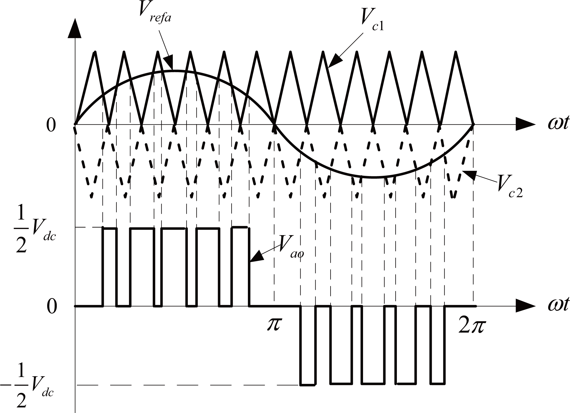
After obtaining three bridge voltages
When an open-circuit fault occurs in any device in the inverter, it will directly affect current paths of the inverter and the bridge voltage of the corresponding phase. According to Eqs (1) and (2), the phase voltage and line voltage of the inverter can be expressed by three bridge voltages. Hence, it is necessary to perform detailed analysis of the bridge voltage when an open-circuit fault occurs. This paper only analyzes the open-circuit fault of a single switching device, and assumes that when the switching device has an open-circuit fault, its anti-parallel diode still work normally. Taking the symmetry of the TNPC into account, the following analysis only takes phase “
Figures 3 and 4 show current paths of a T-type three-level inverter under different phase current directions. In normal condition, when the phase output current
Current paths under different switching states when 
Current paths under different switching states when 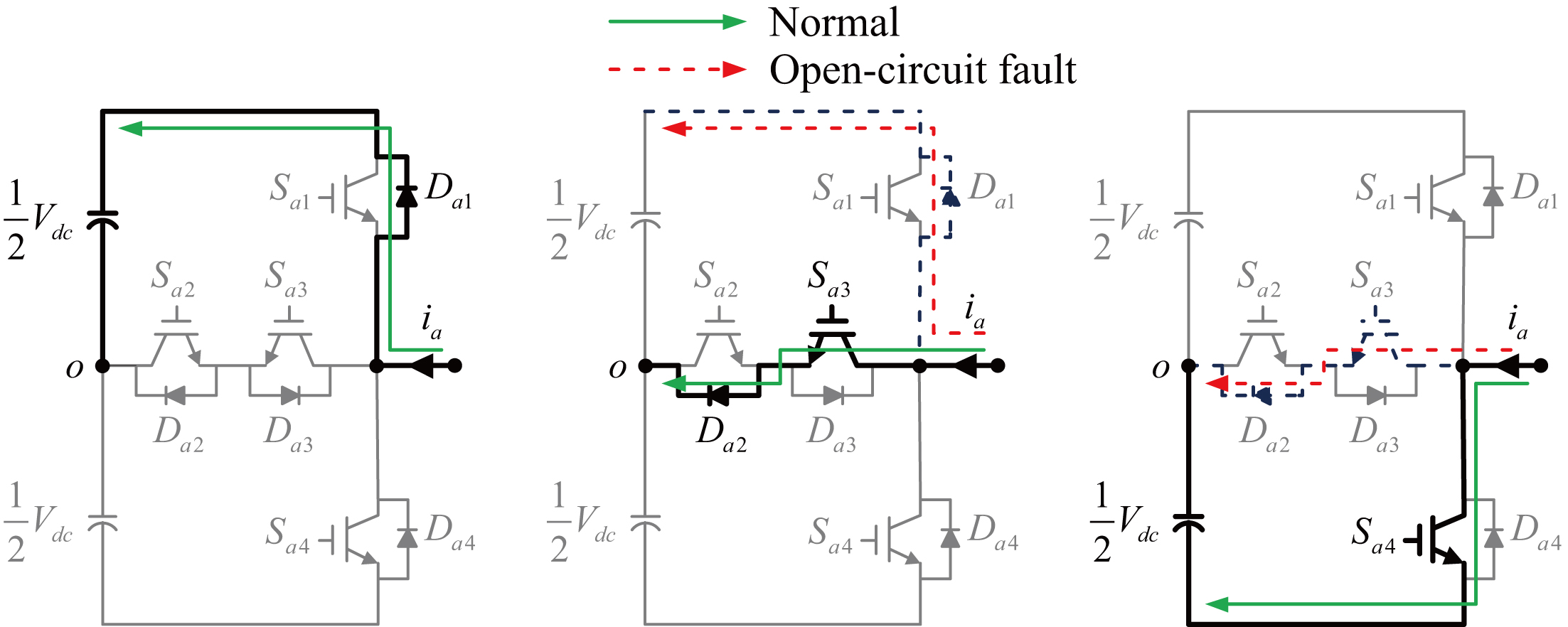
When the open-circuit fault of
Bridge voltage and phase voltage when open-circuit fault of different switching devices. (a) 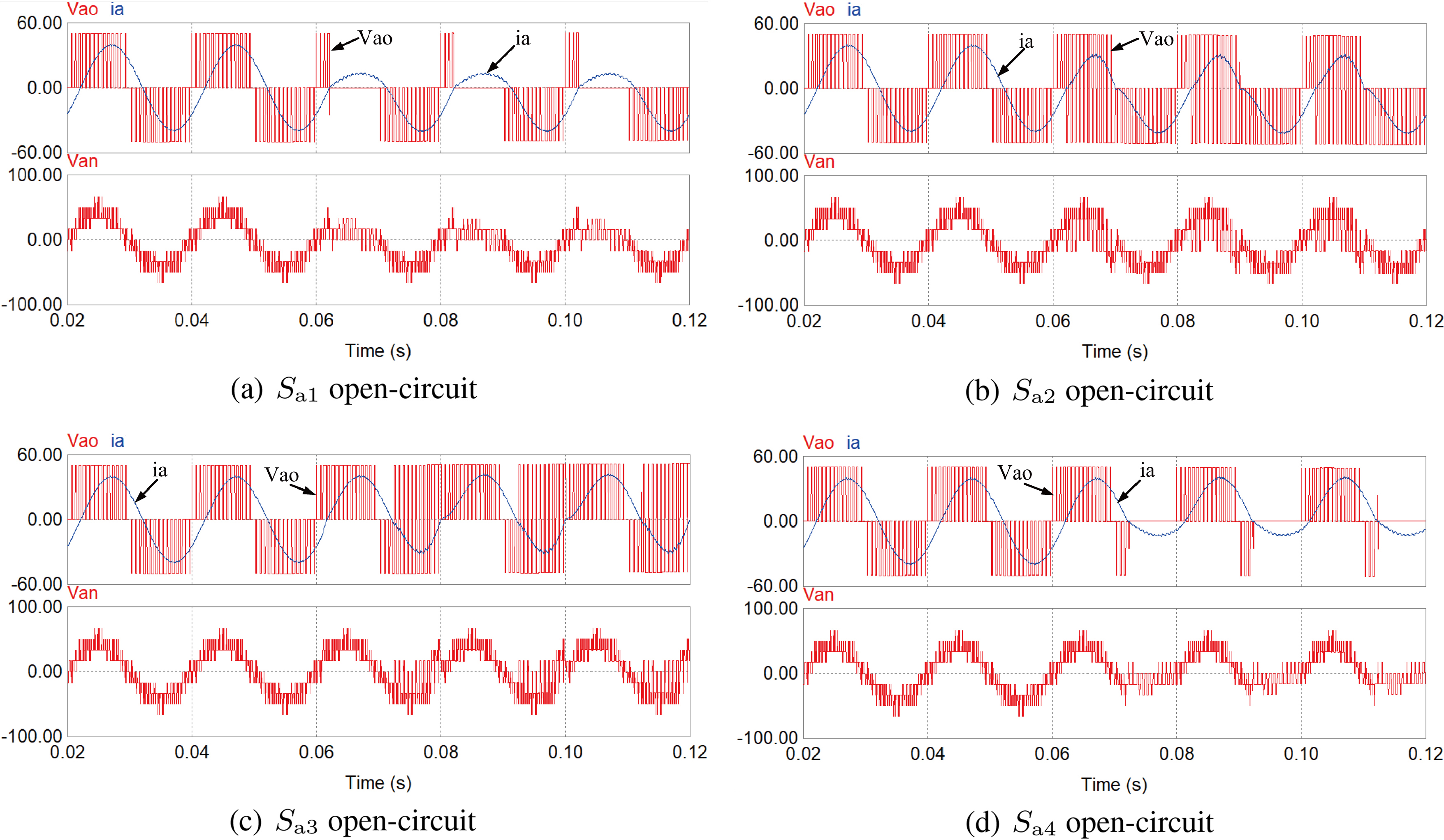
If an open circuit fault occurs in
If the open fault occurs in
In the last case, when an open circuit fault occurs in
It can be seen that when the open-circuit fault occurs, bridge voltage and phase voltage are both affected. Under open-circuit fault occurs in different devices, the switching state of TNPC and the level of the bridge voltage are shown in Table 2.
Switch state and bridge voltage under different fault switch
Taking phase voltage as the research object, the phase voltage is measured and compared with the reference voltage. Then the voltage residual between these two voltages is analyzed to detect and locate the faulty device. In order to eliminate the interference caused by the sudden change of voltage level, both voltages are obtained after filtering. The block diagram of the proposed fault diagnosis method is shown in Fig. 6. In the figure,
Block diagram of fault diagnosis method for open-circuit fault.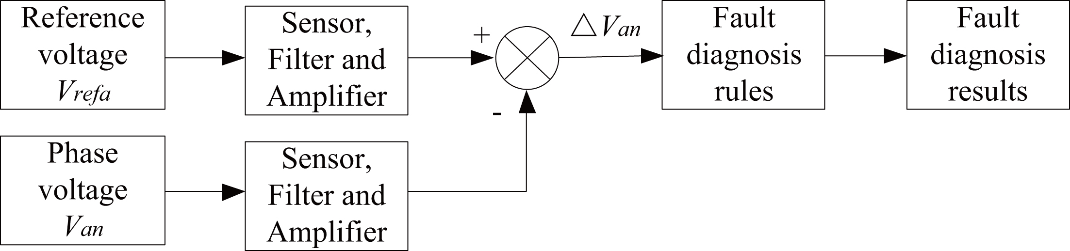
After filter and amplifier, amplitude of the reference voltage and phase voltage are both adjusted to 5 V under normal working condition. The residual voltages when different switching devices under open-circuit fault can be obtained, as shown in Fig. 10. According to the average value of the waveform, these four residual voltages can be divided into two groups, wherein the average values of Fig. 7a and b are positive, and the average values of Fig. 7c and d are negative.
Fault diagnosis rules for TNPC under switching device open-circuit fault
Residual voltages when different switching devices under open-circuit fault. (a) 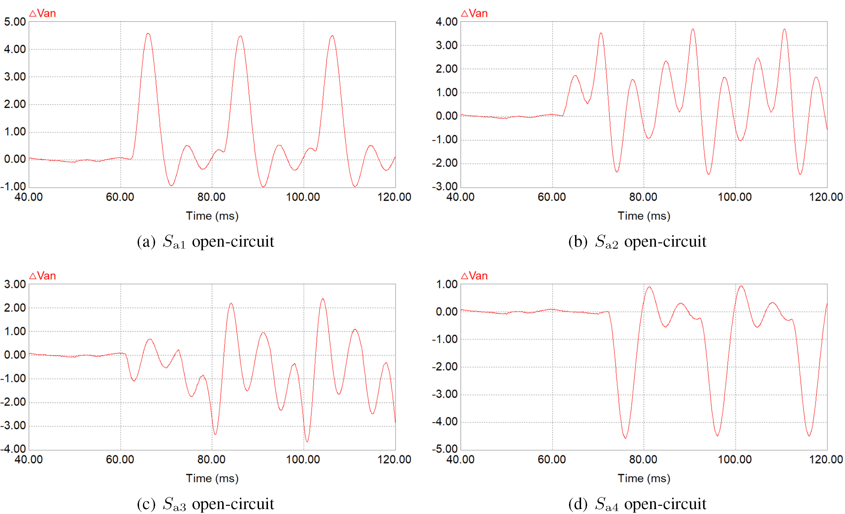
As can be seen from Fig. 7, the two residual voltages of each group can be distinguished according to the difference between their positive and negative peaks, as shown in the Eq. (4).
where
Based on the above analysis, the following fault diagnosis rules can be obtained as shown in Table 3.
An experimental circuit of T-type three-level inverter is set up. The main power device of the inverter is IRG4PC40U and the inverter is controlled by a DSP board with TMS320F2812. The input DC voltage is 100 V. The load of each phase is a resistor of 8
In Fig. 8, the waveform in channel-1 is the reference voltage of phase “
Table 4 shows the experimental data and diagnosis results under different fault mode. The average value of the residual voltage is obtained as follows: after signal preprocessing (operational amplifier circuit, etc.) and high-speed AD circuit, the residual voltage is sampled point by point and then integral calculation is carried out in DSP chip to obtain the average value of voltage. In the experimental, the voltage threshold
Experimental data under different fault mode with the resistor of 8
Experimental data under different fault mode with the resistor of 8
If the resistors of each phase are changed, the diagnosis results are shown in Tables 5 and 6. The resistor in Table 5 is 16
Experimental data under different fault mode with the resistor of 16
Experimental data under different fault mode with the resistor of 32
Table 7 shows the main features of the proposed fault diagnosis method and the other diagnosis methods presented in other literatures. In column of complexity, ‘S’ means simple and ‘C’ means complex.
Comparison of the diagnosis methods
Comparison of the diagnosis methods
Experimental waveforms when open-circuit fault of different switching devices. (a) 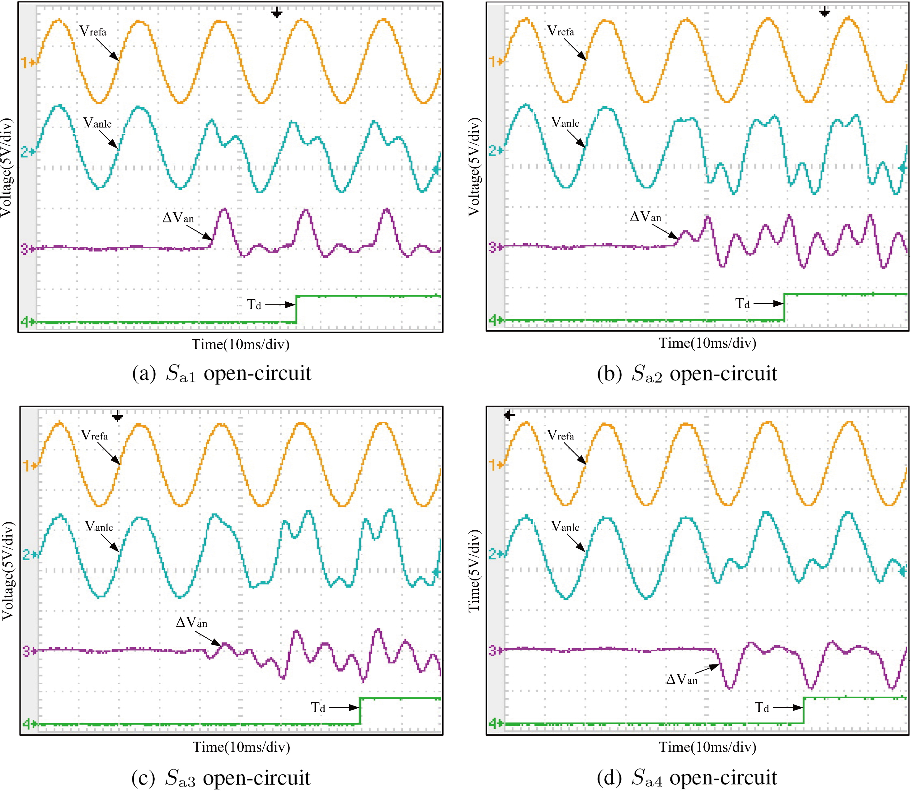
There is one voltage sensor and three current sensors are needed in the papers [15, 16]. In paper [17], three voltage sensors and three current sensors are needed in the proposed method. In paper [20], three voltage sensors and three additional fault diagnosis circuits are needed for fault diagnosis. In paper [21], four current sensors are needed in the paper and these currents must be analyzed with the switching states. As a result, hardware systems of the papers [15, 16, 17, 20, 21] are complex and their costs are high. However, only three voltage sensors are needed in the papers [18, 19] and this paper because the reference voltages can be obtained from the control system. So, hardware systems of the papers [18, 19] and this paper are simple and their costs are low.
In this paper, a method for fault diagnosis of T-type three-level inverter is proposed, which is verified by an experimental system. The main conclusions are as follows.
When there is an open-circuit fault occurs in TNPC, some current path of the inverter cannot be realized. As a result, the bridge voltage will miss some voltage level and the corresponding phase voltage will be affected too. Phase voltage of the TNPC contains enough fault information of the inverter. Through theory analysis and experimental verification, the method based on the residual voltage between the reference voltage and the phase voltage can locate the specific faulty device. The reference voltage of the TNPC can be directly obtained from the control system. Therefore, only three voltage sensors are needed in the method proposed in this paper to acquire phase voltages of the TNPC and it is easy to implement.
Footnotes
Acknowledgments
This work was supported in part by the Zhejiang Province Public Welfare Technology Application Research Project under Grant LGF20F010004, Ningbo Municipal Natural Science Foundation under Grant 2018A610189 and Zhejiang Wanli University Initial Scientific Research Fund for PhD.