






Abstract
Fast steering mirrors (FSM) driven by Piezoelectric transducer (PZT) are widely used in various precision stable tracking systems. Aiming to counteract the hysteresis and non-linear interference in PZT, this work applies a radial basis function (RBF) neural network to approximate its nonlinearity. Adaptive backstepping sliding mode (ABSM) controller combinewith a sliding mode control method and backstepping control is designed. Combining the characteristics of PZT and voice coil motors (VCM), the FSM driven by VCM is designed as the power sub-system to ensure that the large-angle deflection of the FSM can match a wider field of view. The FSM driven by PZT is designed as a correction sub-system, which can adjust the system error within a small range. Finally, the power sub-system and the correction sub-system are combined into a two-level precision tracking system. The simulation results show that the maximum steady-state error of the system is about 15
Keywords
Introduction
In optical tracking and measurement systems, it is extremely difficult to directly finish fast and high-precision tracking due to the large inertia, narrow frequency band, and slow response of large-aperture telescopes [1, 2, 3]. In order to ensure a high-precision tracking of the target, a compound-axis control system is essential. FSM is a device developed in recent years, which is used to control beam deflection to achieve accurate optical axis pointing [4]. Micro-drivers such as VCM or PZT are often used to drive FSM to achieve precise control of the beam direction between the light source and the target. The VCM offers several advantages of simple structure, slightly larger volume, larger stroke, and larger specific thrust [5, 6]. Compared with the VCM, PZT is smaller in size, larger in thrust but short in travel distance, and it offers several advantages such as the convenient control, high displacement resolution, high resonance frequency, fast response speed, no heat, no magnetic interference, high control accuracy, etc. However, non-linear properties such as hysteresis of the piezoelectric material itself will limit the further improvement of positioning accuracy [7, 8].
In this paper, the precision tracking system is designed as a combination of two sub-systems, in which the FSM driven by VCM is designed as the power system, and the FSM driven by PZT is designed as the correction system. The structure of precision tracking system is shown in Fig. 1.
Schematic diagram of fine tracking system.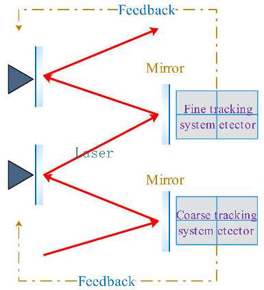
This study uses the LuGre model to describe the hysteresis of PZT, and builds a mathematical model of the piezoelectric actuator, using RBF network to approximate the hysteresis effect. An adaptive backstepping sliding mode controller is designed for the piezoelectric driving FSM system, it can adjust the system errors within a small range. The deflection angle of the FSM driven by PZT is generally small, usually on the order of 10–20 urad, while the deflection angle of the FSM driven by VCM is generally larger than PZT. Therefore, in this paper, the FSM driven by VCM is used as the power system to ensure the large-angle deflection of the FSM. Finally, the numerical simulations are used to verify the performance of the designed ABSM controller as well as the tracking accuracy of the designed fine tracking system.
Taking a certain type of FSM as the research object, FSM is driven by the same four PZT stack drivers, as shown in Fig. 2. A and C are used to push or pull the FSM to do pitching motion, while B and D are used to drive the FSM to do the similar azimuth motion. The driving principles of the azimuth axis and the pitch axis are the same.
Actuator position.
The displacement increments of drives B and D are equal in magnitude, opposite in direction, which can be expressed as.
The drives B and D will conduct two movements with a equal magnitude and opposite direction.
Schematic diagram of FSM driven system.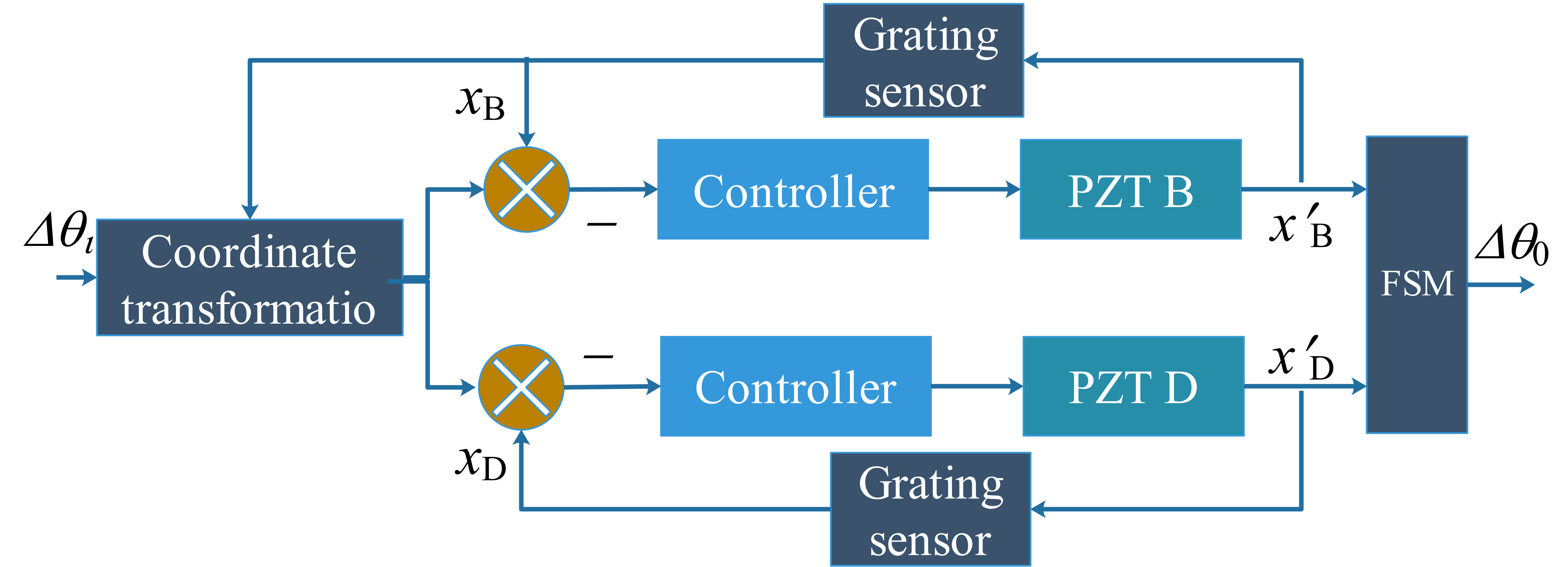
In Fig. 3,
The VCM is also working based on the same principle as the speaker in which the conducting wire is woking in the magnetic field and driven by the electromagnetic force to push the load [9]. Its structure is shown in Fig. 4.
The dynamic equations of VCM are described as follows:
Schematic diagram of the voice coil motor.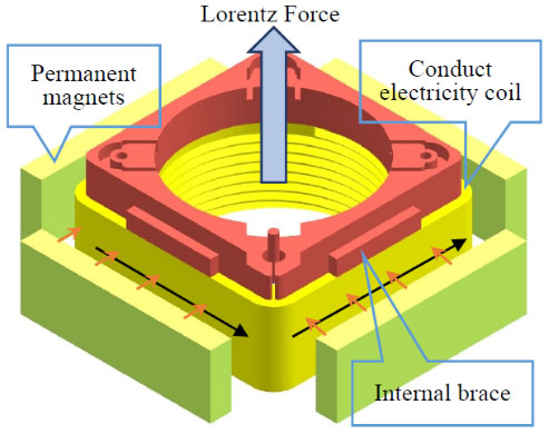
Namely:4
As can be seen from the Eqs (3) and (4), the denominator of the system has the highest order 3, and the numerator is a constant. Third order polynomials must have a real root. In addition, the system is in one-dimensional direction, and two VCM drivers drive the FSM through push-pull method. So, the transfer function of FSM driven by VCM is shown as follows:
PZT drivers are composed with the piezoelectric stacking. Hundreds of wafers are stacked top to bottom one by one to achieve a mechanical connecting, which makes it easier to use low voltage to produce large deformation. The equivalent model of piezoelectric stacking is shown in Fig. 5.
Piezoelectric stack equivalent model diagram.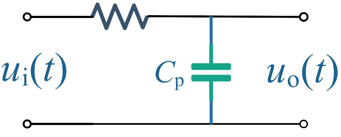
According to Kirchhoff’s voltage law:
Assuming that
According to the deformation characteristics of piezoelectric stack, the relationship between the driving force
The transfer function of the system is:
That
Controller design for correction system
The mathematical model of the piezoelectric transducer can be described by differential equations as follows:
Where
It is defined as follows:
The hysteresis is the main interference of PZTcontrol, but it is actual a kind of friction, which can be described by certain friction model. At present, the main friction models including the LuGre model, bristle model, bliman-sorine model, Stribeck model, Reynold model and so on [10]. LuGre model includes the friction hysteresis, variable static friction force and viscous friction phenomenons, which can fully capture the dynamic hysteresis effect of piezoelectric ceramics. Its mathematical equations of the dynamic friction model can be expressed as:
Because of its simple algorithm and good robustness, the sliding mode control is usually used in systems where model parameters are uncertain [11]. Firstly, the core idea of backstepping method is to decompose the complex nonlinear system. Then the virtual control variables and Lyapunov function are designed for each sub-system. Finally make each sub-system gradually “fallback” to the whole system to bring the system up to the desired performance metrics [12].
From the perspective of system control, the hysteresis is represented by an unknown nonlinear function
RBF neural network is generally composed of three layers, which are the input layer, hidden layer and output layer from left to right, as is shown in Fig. 6.
RBF network structure diagram.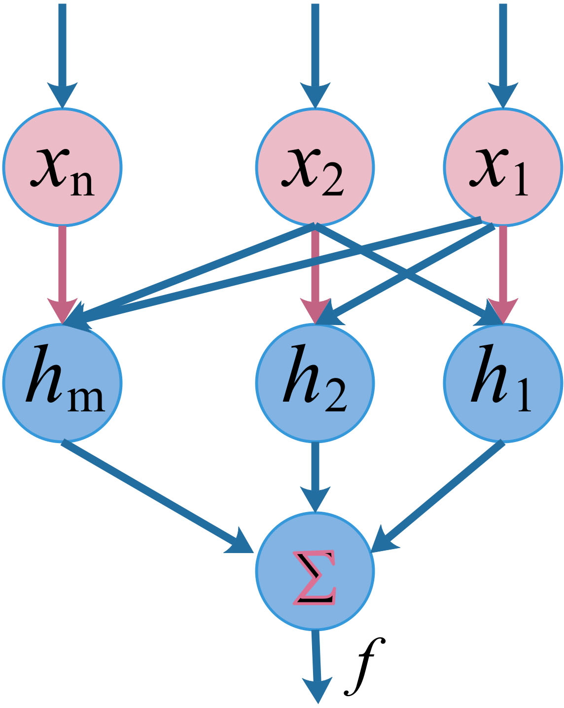
The hidden layer activation function is defined as the Gaussian activation function, and its algorithm for approximating
Define
Define the Lyapunov function:
We can get
Define the switch function:
Take the Eq. (22) into Eq. (19), we can get
Design control rule as follows:
Design adaptive law of RBF network:
Take the Eqs (27) and (26) into Eq. (25) and we can get
Let
so
It can be seen from Eq. (30) that we can make
The structural diagram of the controller can be deduced from above, as is shown in Fig. 7:
Adaptive backstepping sliding mode controller structure.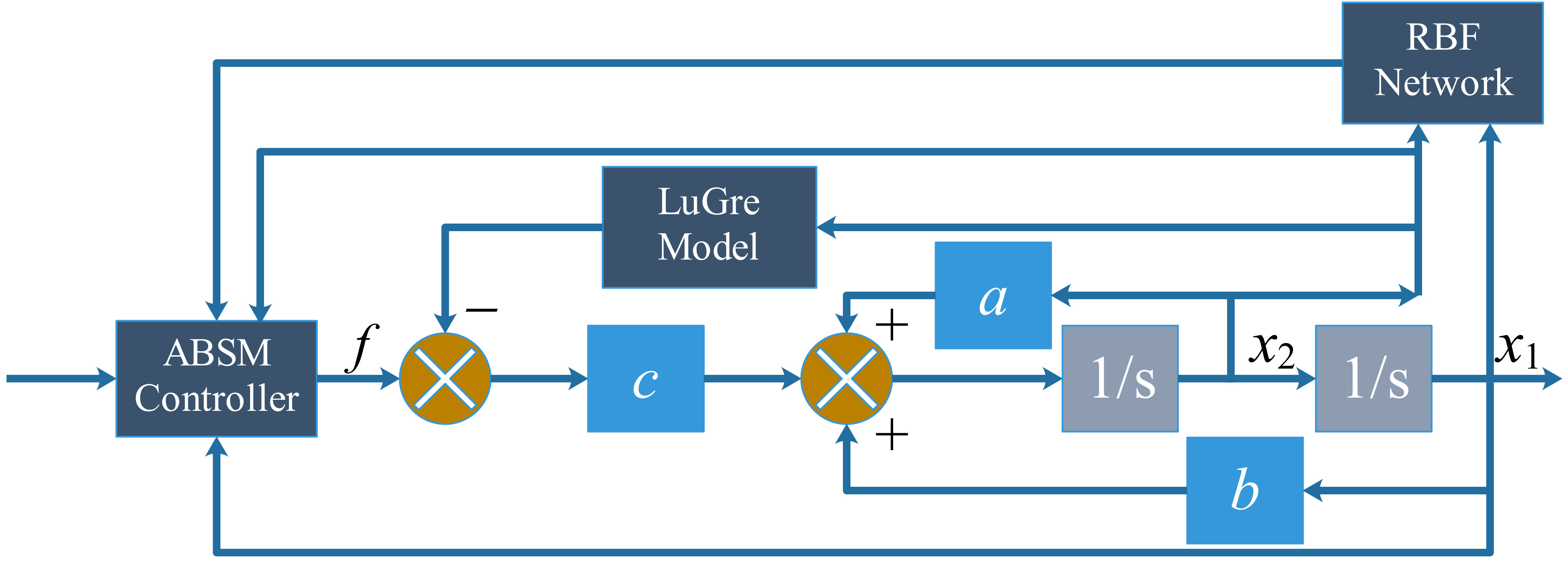
Select the PZT driver produced by PI company, and its run length is 80
Taking
Response curve of step signal.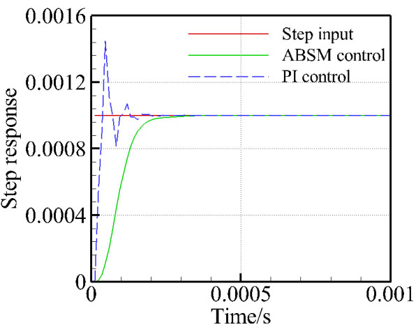
It can be seen from Fig. 8 that the system has a quick response due to its simple structure. However, the driver is seriously disturbed by the hysteresis and the steady state error is increased. Although the response speed of ABSM controller is not quick enough, it can effectively suppress hysteretic nonlinear problems, and adjusting time is only about 0.2 ms. It can be seen from Fig. 9 that, the maximum tracking error is about 57.58
Sinusoidal signal tracking error.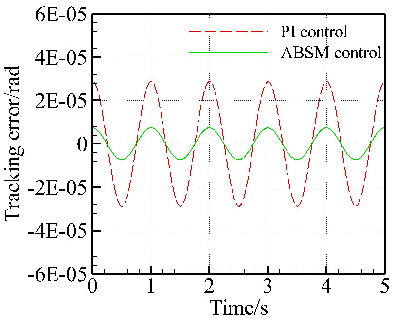
From Section 2 we know that the transfer function of FSM driven by VCM is:
Design the PI controller as
Generally,
satisfying
According to the established and designed mathematical model of precision tracking system controller, we can get the precision tracking system structure as shown in Fig. 10.
Precision tracking system structure.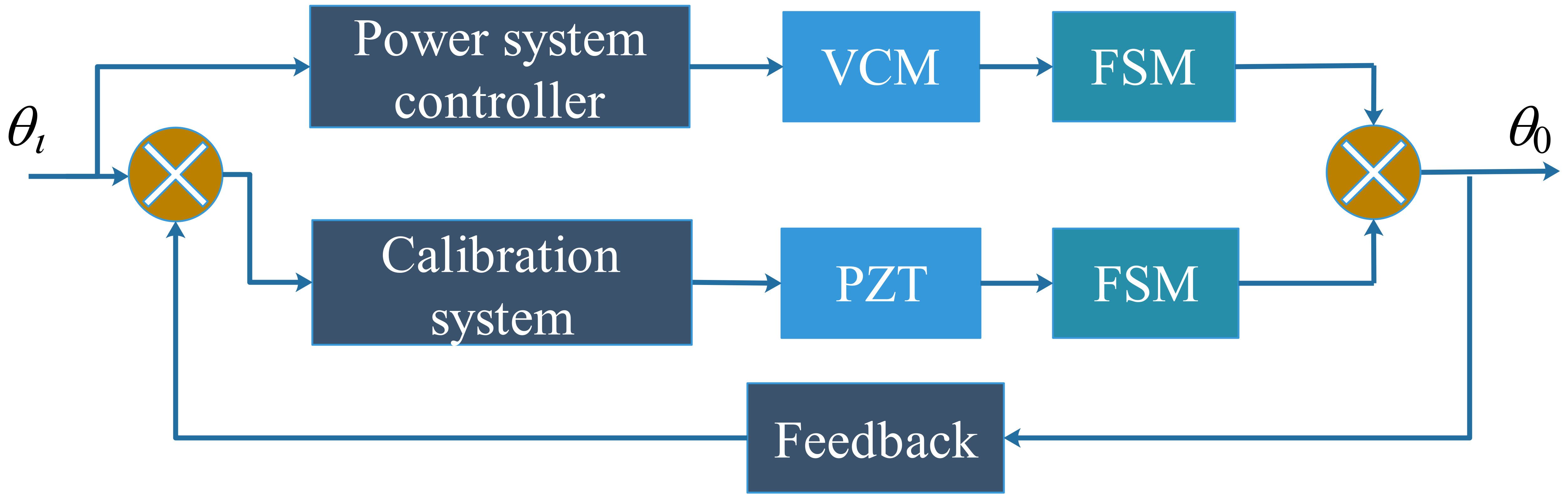
Response curve of step signal.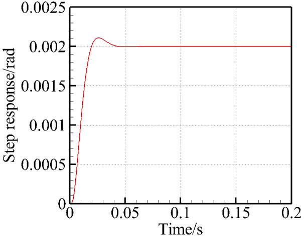
Controlled quantity of correction sub-system.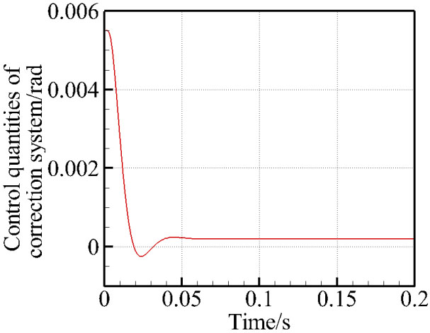
Sinusoidal input.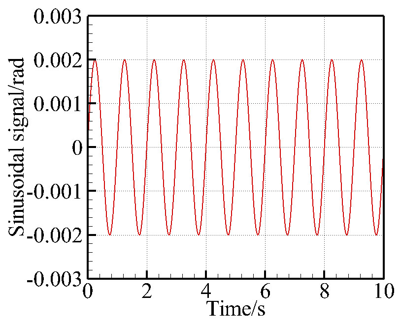
Response error.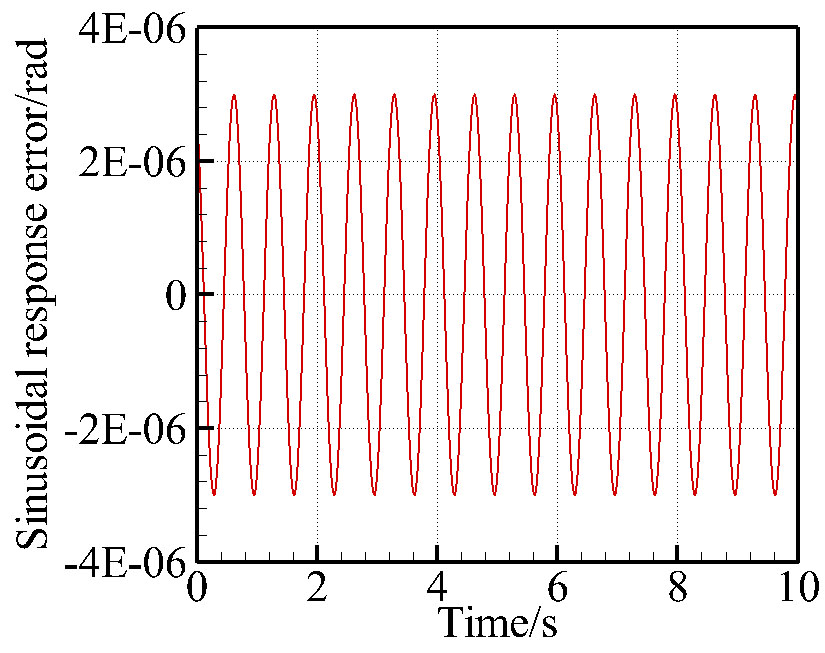
Controlled quantity of correction sub-system.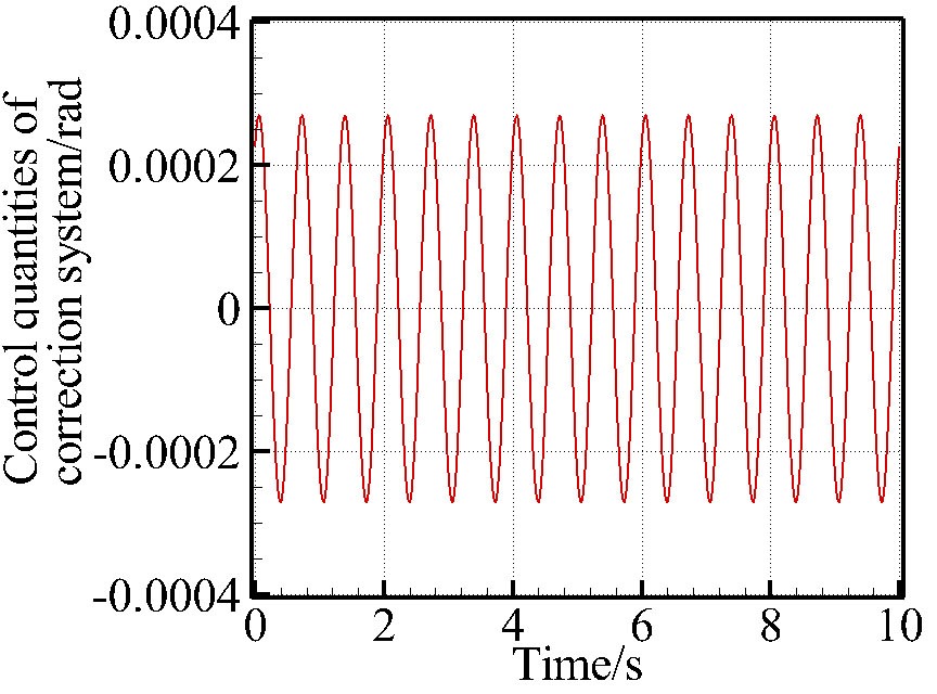
The deflection angle of FSM driven by PZT is generally small. Its tracking accuracy is high but there is hysteresis in PZT. However, the deflection angle of FSM driven by VCM is big, while its tracking accuracy is low. Therefore, VCM is selected as the driver of power sub-system to ensure that the large-angle deflection of the FSM can match the field of view. The FSM driven by PZT is designed as the correction sub-system, which adjusts system errors in a small range.
The parameters of VCM driver are set as follows:
The parameters of PZT driver are the same as that in Section 3.1.3. Take the azimuth axis as example,
It can be seen from Fig. 11 that the response time is about 0.016s, and the overshoot is about 5%. Furthermore, the output curve is smooth without viberation. When the input is
It can be seen from above that the system maximum steady-state error is about 15
The hysteresis nonlinearity of the piezoelectric ceramic actuator will reduce the control accuracy of FSM. Aiming at this problem, this article uses RBF neural network to approximate its hysteresis nonlinearity, and designs ABSM controller, combing sliding mode control and backstepping method. Meanwhile, the FSM driven by VCM driver is designed as the power sub-system, and the FSM driven by PZT driver is designed as the correction sub-system to reduce the error. The simulation results of ABSM Controller show that the error is reduced by 75% compared to PI controller, and chattering phenomenon in sliding mode control is effectively suppressed. The simulation results also show that the response speed of the system is fast, and the response time is only 0.016 s. The correction system can quickly correct the output error of the power system, and the tracking error is on the order of 10
In the further discussion more attentions should be paid on the refine the math model from both the FSM and the VCM. Experiment platforms and comparisons are essential to verify the improvement numerical algorithms.