
Abstract
With the development of technology, the application of intelligent coal gangue sorting is more and more favored by coal mining enterprises. The coal gangue intelligent sorting system has higher requirements on the coal conveyor belt. The traditional transmission system has the problems of slow speed response, unstable operation, high energy consumption and jitter in the process of speed change. Using PLC, touch screen, frequency converter, RS-485, sensors and so on, the speed control and speed monitoring system of belt transport mechanism is constructed. By analyzing the error law of the system speed control and using Numpy system analysis and calculation, speed pre-compensation can be made. Then by controling speed precision through the PID and monitoring display through the time-speed curve, the real-time automation gives an alarm for abnormal speed situation. According to the speed requirement of the intelligent sorting system of coal gangue, the system can quickly reach the predetermined speed value, and effectively eliminate the shaking phenomenon in the process of changing speed. The system has strong universality, easy maintenance, and stable speed control, which is conducive to improving the reliability and efficiency of the intelligent sorting system for coal gangue and reduceing transmission mechanism wear caused by dithering.
Introduction
Speed control is widely used in industrial production, and the most common is through the frequency converter for belt conveyor speed control [1, 2]. Belt conveyors mainly use friction to drive the transport of objects. Belt conveyor are applicable to a wide range, not only to state-owned enterprises and private economy, but also widely to modern enterprises and industry [3, 4]. Especially in the multi-process production line, each process can be completed in order during the process of belt transportation with high flexibility, high transport efficiency, strong transport capacity, and relatively reliable operation, so the application is very wide. In coal production enterprises, belt conveyors are widely used, one generally used in long-distance coal transport. The speed control of the conveyor belt is automatically adjusted according to the size of the conveyor belt ore transport. The ore transport is generally divided into three grades: small, medium and large, and the corresponding speed is also divided into three grades: low speed with small transport volume, high speed with large transport volume [5, 6]. Many people put forward their own views and design schemes about the design of conveyor belt speed regulation system. These schemes focus on energy consumption and anti-jamming capabilities. In order to reduce the conveyor belt idling and energy consumption, Xi Cungen designed the coal mine transport adaptive control system; Cao Jiangwei and others design an adaptive speed regulation system which was based on RBF-PID controller. Then, They advanced a method to reduce the energy consumption by analyzing the relationship between the energy consumption of the belt conveyor, the amount of coal and the belt speed; Wang Ben proposed a speed control system based on fuzzy PID theory, which improved the adaptive ability and anti-interference ability of the system.
In recent years, the intelligent production of coal has been continuously improved, especially the sorting of coal gangue. With the automation is getting higher and higher, the current intelligent sorting system mainly carries out automatic sorting through image recognition combined with intelligent manipulator, as shown in Fig. 1. The image recognition determines that the speed of transport of stones (non-useful coal mines) cannot be too high, and the manipulator needs a relatively constant operating speed to grasp stones. Therefore, in view of the gangue intelligent sorting system, in the stage of automatic sorting, the speed of the conveyor belt is precisely controlled and monitored, which is convenient for the debugging and operation of the sorting system, and can also improve the accuracy and stability of sorting. By pre-compensating the speed of the asynchronous motor for its own error, the speed control deviation of the conveyor belt is effectively reduced, and then the speed of the conveyor belt can be controlled precisely by using PID to further regulate the speed of the conveyor belt.It is beneficial to eliminate the jitter phenomenon in operation and improve the accuracy and stability of automatic sorting of gangue intelligent sorting system [7, 8].
Intelligent sorting system for coltan.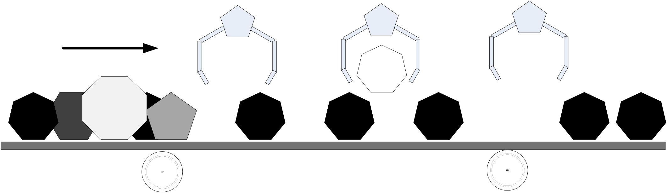
The frequency control system based on RS-485 bus takes Mitsubishi PLC as the control core, and carries out frequency control and speed measurement control on the motor through encoder, frequency converter, touch screen, etc. In order to realize the continuous adjustment of the operation of the motor, the rotating encoder is used to detect the pulse density signal to reflect the speed of the motor and realize the speed feedback. The given value of speed displayed in the touch screen and the feedback measurement value of speed are compared, and the program is written to alarm and display the fault. Through the design of the system, the requirements of RS-485 bus frequency conversion speed regulation monitoring system can be realized to ensure that the motor runs according to the actual requirements and meet the requirements of conveyor belt speed of gangue intelligent sorting system. The overall design framework is shown in Fig. 2.
System design framework.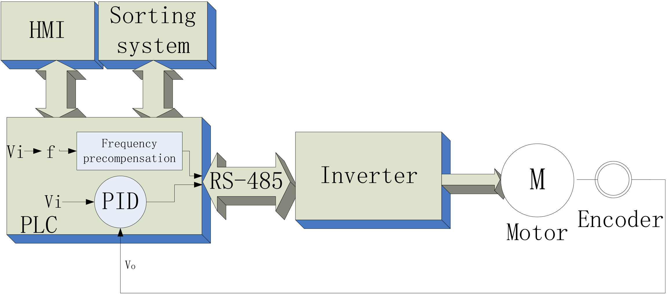
The realization of system hardware mainly consists of PLC, frequency converter, encoder, touch screen and so on. By analyzing the velocity, the velocity compensation is introduced to make the output nearer to the target value. PID control is introduced to improve the output accuracy.
PLC communicates with frequency converter through RS-485, making the system simple in structure, improving the reliability of the system and making it easy to maintain. The touch screen is an ideal human-computer interaction device with powerful function and intuitive information presentation. The touch screen has clear graphics, simple and convenient operation, large amount of information and less space occupation. The feedback signal is then transmitted back to the PLC via the rotary encoder speed measurement system, and the touch screen reads the speed data from the PLC. Real-time display and show speed running status through curves. The curve displayed by the touch screen can clearly reflect whether the motor operates according to the set requirements.
Inverter setup and control
Inverter settings
Inverter (Mitsubishi) initialization ALLC set to 1, PR.117 set to 1, PR340 set to 10, PR.79 set to 0. If E.PUE alarm occurs, please set PR121, PR122 to 9999. If error is still reported, check the communication line. The hardware circuit connection between inverter and PLC is shown in Fig. 3.
The PLC networking module is connected to the Inverter network line.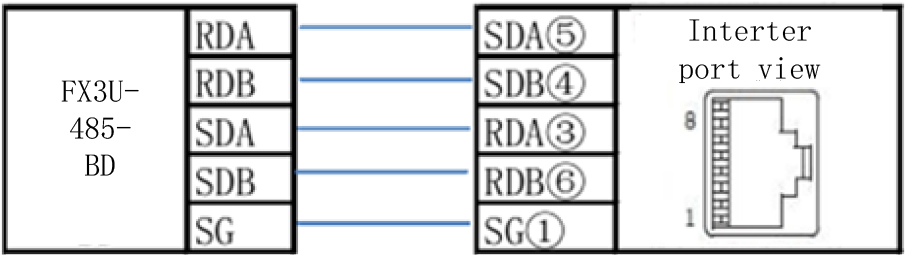
Inverter reset: by executing IVDR instruction (set station number as 1, channel 1), H9696 is written into H0FD, H0 is written into H0F9 [9, 10]. The function of this program is to automatically reset the frequency converter and switch to NET mode.
The motor is rated at 1450 rpm, with anoperating frequency of 50 Hz, Slip rate “s” is 1/30, and a magnetic pole logarithm p of 2 [11].
According to the speed formula of three-phase asynchronous motor, the functional of power frequency “
Known
The formula is simplified to:
The motor has a gearbox with a multiplier (1/10), the speed multiplied by K10, and the frequency instruction is in 0.01 Hz, so the frequency is multiplied by (divided) by K100.
After a series of conversions, the input speed of the touch screen is written into the frequency converter through IVDR instruction, as shown in Fig. 4; The output frequency of the converter read by the IVCK instruction is displayed by the touch screen after conversion. The reading process is shown in Fig. 5.
Writing process.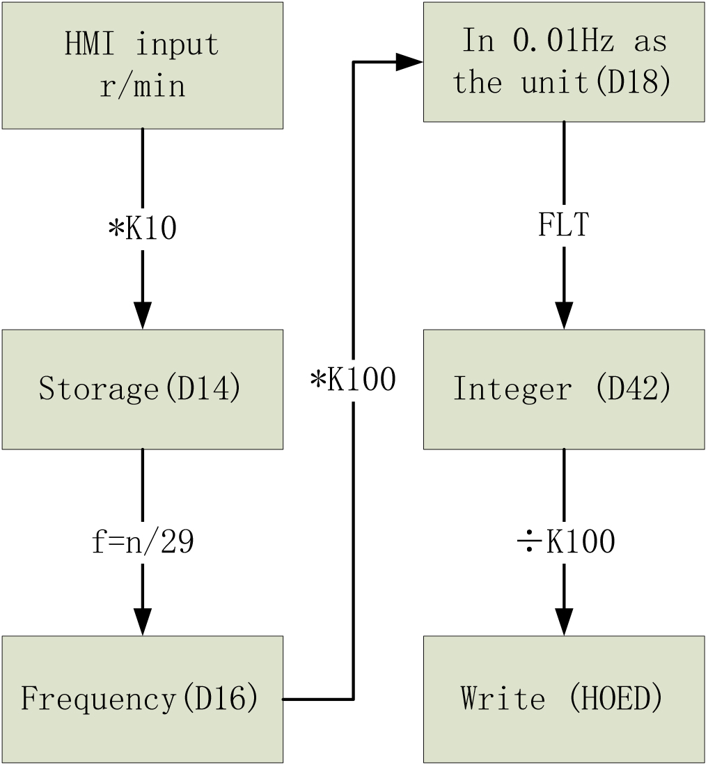
Reading process.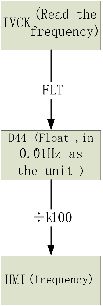
The system uses the M method to measure the speed. What is more, the measurement scheme does not need to use the timer function, only through the special instructions to read the encoder feedback to the PLC data. The motor speed can be calculated in the computer, The velocity process is shown in Fig. 6. the program structure is simple with high efficiency.
Velocity formula:
In the formula
The formula is simplified to:
Velocity process.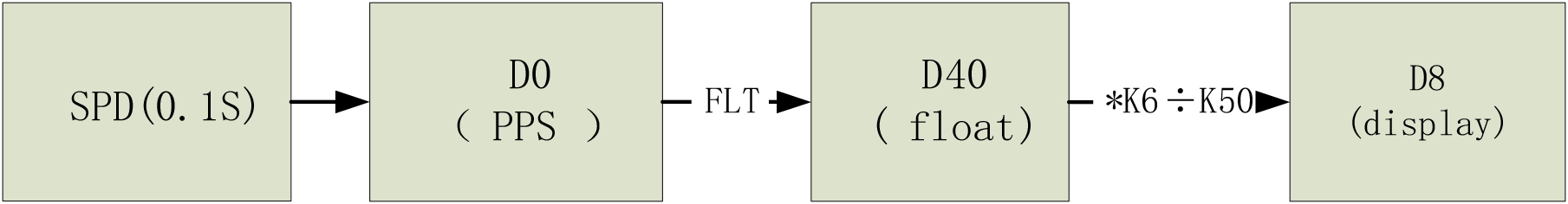
The touch screen is mainly used for control and monitoring, and the speed abnormal alarm is also designed. Download the screen program (as shown in Fig. 7) to the TPC7062KX touch screen, which is connected to the Mitsubishi PLC via a programming port. After the PLC converts the data, the drive is controlled by RS-485 communication line. The inverter outputs the frequency signal according to the given signal, drives the motor to run, the pulse density signal measured by the encoder is input into the PLC. The PLC obtains the pulse density signal by calculating the actual speed. The motor speed curve is displayed through the touch screen. Compared with the target speed, it is displayed in the touch screen. For cases with large errors, the corresponding program is written to realize the alarm function and the fault situation is stopped by PLC.
Normally functions the interface.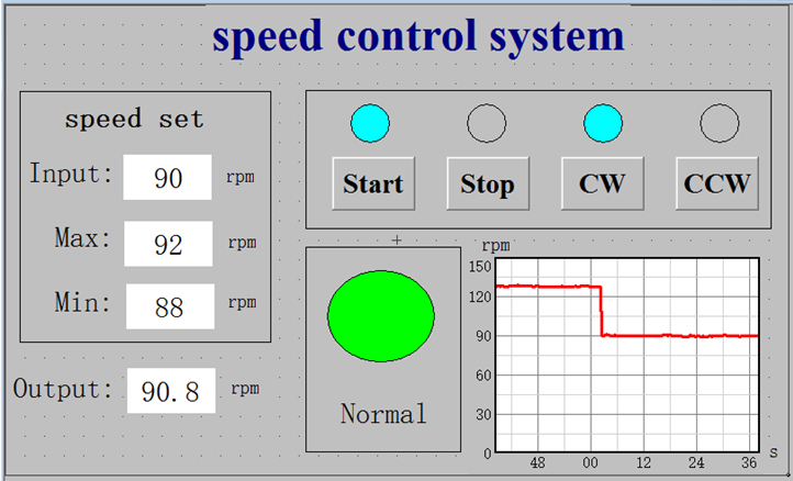
Speed analysis
Through the test, as shown in Table 1, it is found that there is a large gap between the predetermined speed and the measurement speed. Especially at low speed, the relative error is comparatively large. It can be seen from the Table 1 that the error is as high as 16% at low speed, while the error is the smallest at the medium speed.
Compensation pre-speed measurement error gauge
Compensation pre-speed measurement error gauge
After measuring the error curve, using of numpy system to calculation and analysis, the curve function is fitted out and polynthic calculation is introduced in the process of data processing. In order to obtain a more accurate fitting curve, according to the characteristics of the error curve, it is divided into four segments (10–40, 40–60, 60–80, 80–100). The fitting curves of two segments are shown in Fig. 8.
Segment Fit Graph (two of them).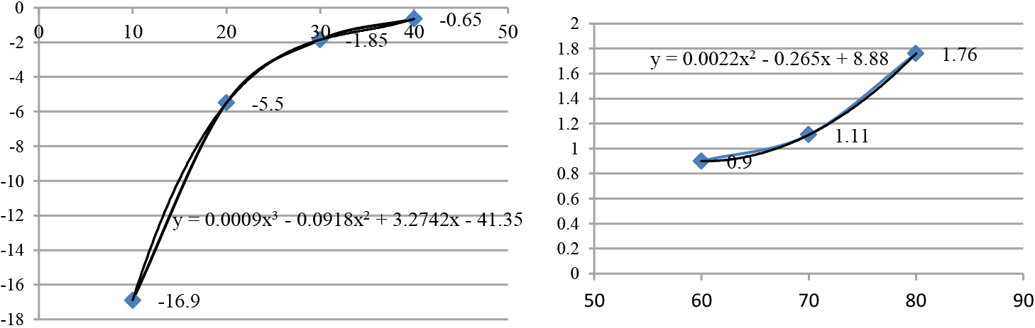
According to the fitting function, the error has been greatly improved after the speed compensation on system. It can be found that the average error value was from the original maximum of 16.9% to 1.65%, an increase of 10 times. It changes from the original maximum of 22% to 6.3% in the absolute error of 10 rpm. After compensation, the velocity error curve is shown in Fig. 9.
Compensated speed measurrment error curve.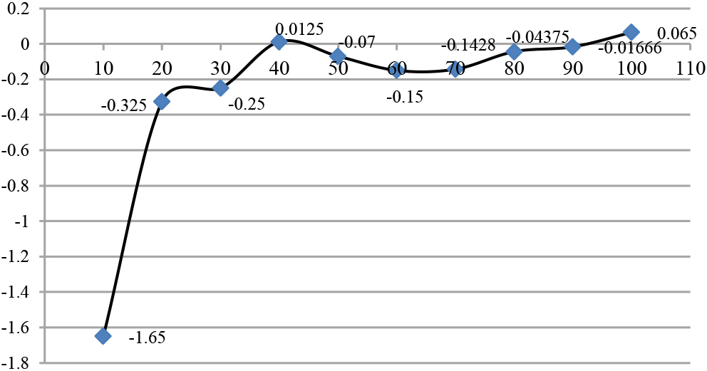
The effect of referencing the PID directly.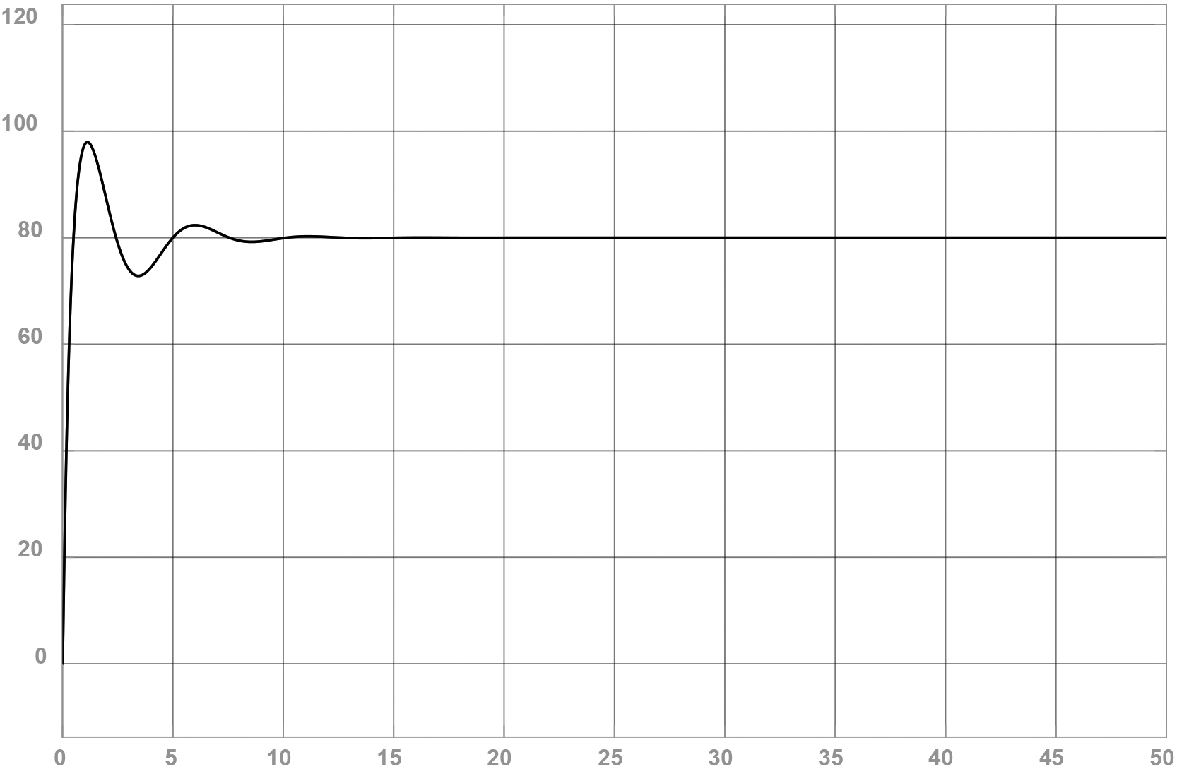
Delay into the PID curve.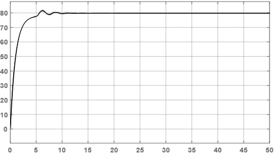
In order to control the conveyor belt speed with high precision and improve the anti-jamming ability of the conveyor belt, PID control is introduced into the control. The PID control equation for the conveyor belt:
In the formula:
The role of
The speed error before the conveyor belt is stored by timer in the control, and the speed situation in front is fed back into the equation, which can preferably reflect the trend of velocity variation and achieve faster response and precise speed control [13].
Using PID control directly will cause large overshoot (as shown in Fig. 10), so that it will make the conveyor belt vibrated and worn. In order to achieve better control effect, the PID delay is introduced when the conveyor belt starts or changes speed. The PID is introduced When the speed is close to the target value. The effect is shown in Fig. 11.
Summary
This project mainly starts from the application of variable frequency speed control technology, non-stage speed control, and making a analysis of speed regulation with the predetermined value of the distribution software. It integrate with the using of application of RS-485 communication lines, starting from the peripheral wiring of the drive and PLC, setting the parameters of the drive and controlling the starting, stopping and running of the motor with the PLC. Finally, after debugging the system hardware and software operation and drawing out the system operation interface, the motor was observed whether is running on the actual curve.
The minimum maximum value should beallowed to make a special settings for specific occasions in the system. For example, As shown in Fig. 6, When the output value is between the maximum and minimum, the status indicator is in green (normal); otherwise, the status indicator is in red (fault).
After completing the basic speed control system hardware and software design, the speed measurement scheme of the monitoring system is studied and the control function of the monitoring system is tested and verified many times. The experimental tests show that the intelligent sorting conveyor belt speed control system designed by this project realizes the continuous speed control of frequency converter by using the touch screen. Through the frequency analysis of the conveyor belt controlled by the asynchronous motor, the control frequency is pre-compensated according to the feedback speed error, which can effectively reduce the inherent speed error.
According to the change of speed error in the recent moment, PID adjustment is made to further improve the accuracy and stability of conveyor belt speed. The jitter phenomenon of conveyor belt can be reduced well with the testing. It makes the intelligent sorting system of coltanis satisfied with coal conveyor belt speed and improve the reliability and sorting efficiency of coal zircon sorting.
Footnotes
Acknowledgments
The work is supported by the science and technology program of Guangdong province (2014A040401009), Industrial Robot Technology Collaborative Innovation Centre project of Qing yuan Polytechnic and Intelligent measurement and control technology research team project provided by the Guangdong Education Department.