
Abstract
A modification to the gear tooth surface is crucial for reducing whistling noise generated by gearboxes of electric vehicles. Using the orthogonal test method, this paper studies geometry parameters of gear pair and the effect of load conditions on modification parameters of tooth surface. To achieve this, the paper develops various test models of gear pairs based on MASTA and then corrects the gear profiles according to load distribution state. The influential factors of gear transmission to modification parameters of tooth surface are thereby intuitively analyzed.
Finally, a prediction model of the result of gear modification is built, based on test parameters, by method of support regression vector machine, providing a valuable reference to determine the tooth-surface modification parameters of the transmission gear of electric vehicles.
Introduction
With the implementation of “New Energy Vehicle Industry Development Plan (2021–2035),” the number of electric-powered new energy vehicles has burst. New energy vehicles have gradually won the favor of OEMs and consumers due to their superior qualities, such as energy efficiency and environmental protection. Due to the absence of engine noise in electric vehicles and the significantly higher transmission speed compared to conventional fuel vehicles, the gearbox whistle has become one of the most significant noise sources in electric vehicles [1].
During the working process, the gears transmit power via alternating meshing. However, due to manufacturing error, assembly error, and the deformation of gear pairs during loading process, the force on the tooth surfaces of the gear pair is uneven, resulting in the phenomenon of load impact and whistling [2]. In general, the micro-geometric modification of gears is used to improve meshing status and load distribution on tooth surface, thereby enhancing the gears’ transmission stability, transmission quality, and service life [3]. According to Wu Junjie [4], the reducer is the primary source of noise in an electric vehicle. By modifying the gear tooth surface, the contact state is enhanced, the transmission error is decreased, and the product’s overall NVH is enhanced. Wei Guoxing [5] developed an optimized study on spur tooth surface using energy method and genetic algorithm. Zhao Min et al. [6] took the specific secondary reducer of a new energy vehicle as an example, analyzed the load per unit length, transmission error, and NVH, and then proposed an alternative diagonal modification method. Variable approximation replaces diagonal modification slope variation, which simplifies parameter estimation. The authors of Xu Zhongsi et al. [7] suggested an optimization method for modification parameters that considered both transmission error and tooth surface contact stress. Jia Chao et al. [8] examined the effect of coincidence degree on the parameters of tooth surface alterations and optimized the parameters. Therefore, a good strategy for modifying the tooth surface can effectively enhance load distribution during gear meshing, thereby reducing gear vibration and suppressing gear whistling noise. Unfortunately, none of these preceding studies included a quantitative analysis on the parameters of tooth surface modification.
Throughout the research, the orthogonal test design method is utilized to establish a test plan based on gear design parameters, the position of the gear pair, and the applied load. MASTA is employed to manually trim the gear sets following the same standard in each test plan, and then analyzes the gear sets with trimming parameters and influencing variables. Finally, the prediction model of the support regression vector machine of gear pair parameters and modification parameters is developed to accurately forecast the modification parameters.
Theoretical analysis
Gear mesh
As the gears mesh, they enter the meshing line; the initial contact is SAP, and the final contact is EAP.
In the process of transmitting power, the meshing stiffness of the teeth changes periodically, so the actual meshing point is not always on the meshing line. The instantaneous speed difference will cause meshing interference and impact, resulting in vibration and noise.
The transmission error is the main source of excitation, which can be defined as the angular difference between the theoretical meshing position and the actual meshing position of the gear pair [9]:
In particular,
For reducing meshing interference and impact, improving the contact state of the tooth surface, and decreasing the TE gears need to be modified.
Process diagram of gear meshing.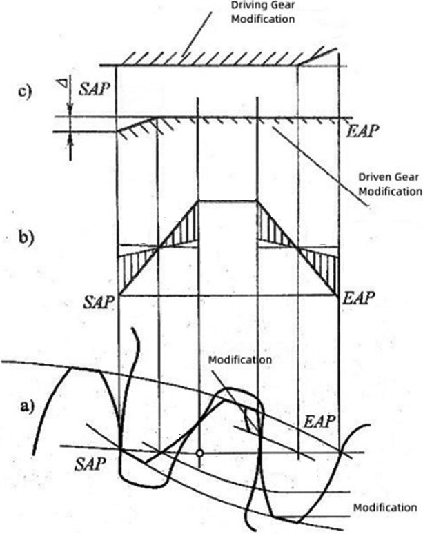
Support Vector Machine is a two-class classification method based on statistical learning theory, and its principle is to map nonlinear inputs into high-dimensional feature space through kernel functions, and then to build a linear model in high-dimensional feature space [10, 11]. It is especially suitable for small and medium-size samples, nonlinear, high-dimensional classification, and regression problems.
Suppose there is a training sample set in a feature space:
In this example,
It is the separation hypoplane
Since completely linearly separable data is almost non-existent, a relaxation factor
To determine the separation hyperplane that maximizes the classification interval, the optimization problem must be considered:
Where
For the nonlinear classification problem in the input space, transform it into a linear classification problem in a certain dimensional feature space via nonlinear transformation, learn a linear support vector machine in the high-dimensional feature space, and replace the inner product with the kernel function:
In the dual problem, the kernel function
A support vector machine is employed in regression problems, which uses a constant
The objective function of the regression model can be defined as follows:
Relaxation factors
In summary, support vector machine regression is a supervised learning algorithm, to perform discrete value prediction by finding the optimized fitting hyperplane of multidimensional data. Its superiority is the calculation complexity increases insignificantly when data dimension expands and meanwhile keeps a high forecast precision. There are researches that have applied support vector machine regression in the design area of mechanical parts which achieve good results [12, 13].
Model construction of involute cylindrical gear pairs
MASTA is a professional software for the design and manufacturing of transmission systems. Functions include modeling of transmission system, analyzing, optimizing and so forth. It is a commonly used CAE software for the analysis of gear tooth modification [14, 15]. To examine how gear parameters and the state of the system where the gear pair locates effect on surface modification parameters, a simple gear pair transmission system is established within MASTA software. The diagram is in Fig. 2 as follows.
Schematic diagram of a gear pair transmission system.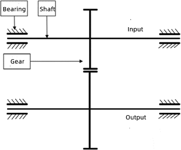
A simple transmission system consists of a pair of gear sets, an input shaft, an output shaft, and concept bearings that are used on both ends of the input shaft and output shaft. The adopted concept of bearing does not consider the influence of bearing assembly relationship and bearing structure on the system. The input shaft and output shaft are both solid shafts with diameter of 25 mm and length of 150 mm.
A gear pair is characterized by the following parameters: gear module, helix angle, pressure angle, number of teeth, addendum coefficient, dedendum coefficient, modification coefficient, tooth width and center distance between gear pairs. There is a certain correlation between these main parameters of gears. For the same center distance, transmission ratio, modulus, helix angle and pressure angle are the primary parameters used to design gear pairs. The modification coefficient is usually calculated according to ISO 21771 based upon the above parameters. Addendum coefficient and dedendum coefficient are mainly used to get the heights of the tooth tips and tooth roots of the calculated gear pair. Therefore, this paper only focuses on the center distance, transmission ratio, modulus, helix angle, pressure angle, and tooth width. These five parameters are the key factors to study tooth structure. Moreover, influences of the load on the transmission system and the axial position of the gear pair in transmission system are also considered.
Orthogonal design is a statistical approach to solve multifactorial issues. It is commonly employed when the result is influenced by multiple factors and is required to clarify the effect of each factor or find the best parameter combination. Its advantages are fewer analysis times, high efficiency, and easy implementation. Now it has been widely applied in the design area of mechanical parts, to effectively analyze the influence of gear tooth modification parameters on meshing results [16, 17].
Based on above analysis and settings, the orthogonal method is used to design 8 factors, and each factor has 5 levels, yielding to a total of 50 groups of experiments. The orthogonal design experiments are described as follows.
Orthogonal design table
The modification methods shown in ISO21771 can be divided into three categories, namely, helix modifications, transverse profile modifications, and triangular modifications. Among these, transverse profile modifications and helix modifications are the most frequently adopted modification methods. The helix modification methods include helix slope modification, helix crowning and helix end relief. The transverse profile modification methods include transverse profile slope modification, profile crowning and tip and root relief, amongst which tip and root relief is not commonly employed [18]. Helix end and tip relief are designed to avoid the crush of tooth edge due to increasing stress distribution but are not crucial to the stress distribution on tooth surface.
Modification method diagram.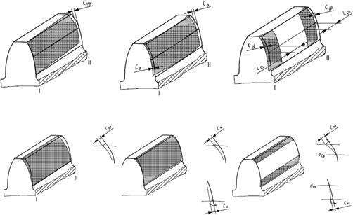
This test follows the common methods of transverse profile modifications and helix modifications, including 4 methods: helix slope modification, helix crowning, transverse profile slope modification and profile crowning.
A pre-finish at the distance of 10% from tooth ends is conducted, with the amount of 10
Comparison of trimming results.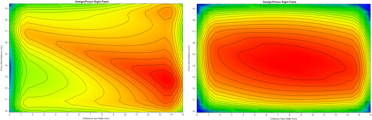
Shows the modification results as follows
Generally, transmission error of gear pairs and maximum stress on tooth surface are effectively reduced after the tooth surface modification. In addition, meshing state on the tooth surface is greatly improved. Above all, this paper identifies the relationship among the geometry, torque, position in system and trim amount of each modification method of gear pairs through intuitive analysis.
Intuitive analysis
Analysis of helix angle modification parameters
The size and direction of the helix angle modification varies under the influence of different levels of various factors, as shown in Fig. 5. The most important factor affecting the modification of helix angle is axial position of the transmission system where the gear pair resides. Furthermore, it was discovered that when the gear pair is in the middle of the shaft system, the helix angle modification is the smallest, and when one-fourth of the distance away from the edge of the shaft system, the modification amount is the largest. The difference in the position of the gear pair also results a significant change in the modification direction.
Results of helix angle modification.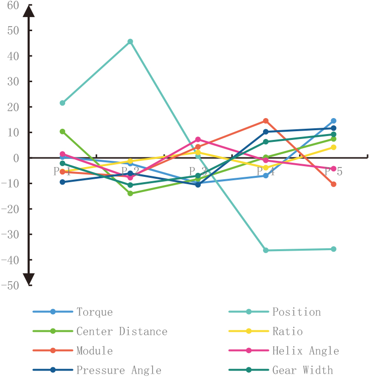
Figure 6 depicts the modification of the helix crowning under the influence of different levels of various factors. As the torque is continuously increased, the crowning amount shows a noticeable increasing trend. Then within modulo range, the crowning amount increases and then decreases as the modulo rises. The peak value is reached when the modulo is 2.5. Meanwhile, changing pressure angle causes a significant change in crowing amount, but no clear changing pattern is observed.
Results of helix crowning modification.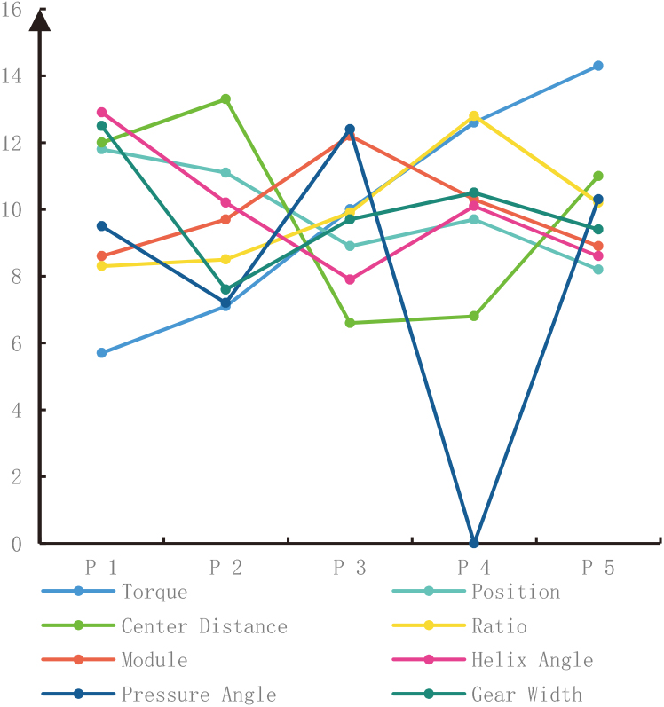
As shown in Fig. 7, all parameters present no clear linearly changing pattern for transverse profile slope modification. Changes in helix angle have little effect on the amount of profile pressure angle modification. Nonetheless, an increase in pressure angle and torque will cause the amount of transverse profile slope modification to increase within a broader parameter range. It is also found that modification amount of transverse profile angle drops within a wide parameter range when the center distance gets larger.
Results of transverse profile slope modification.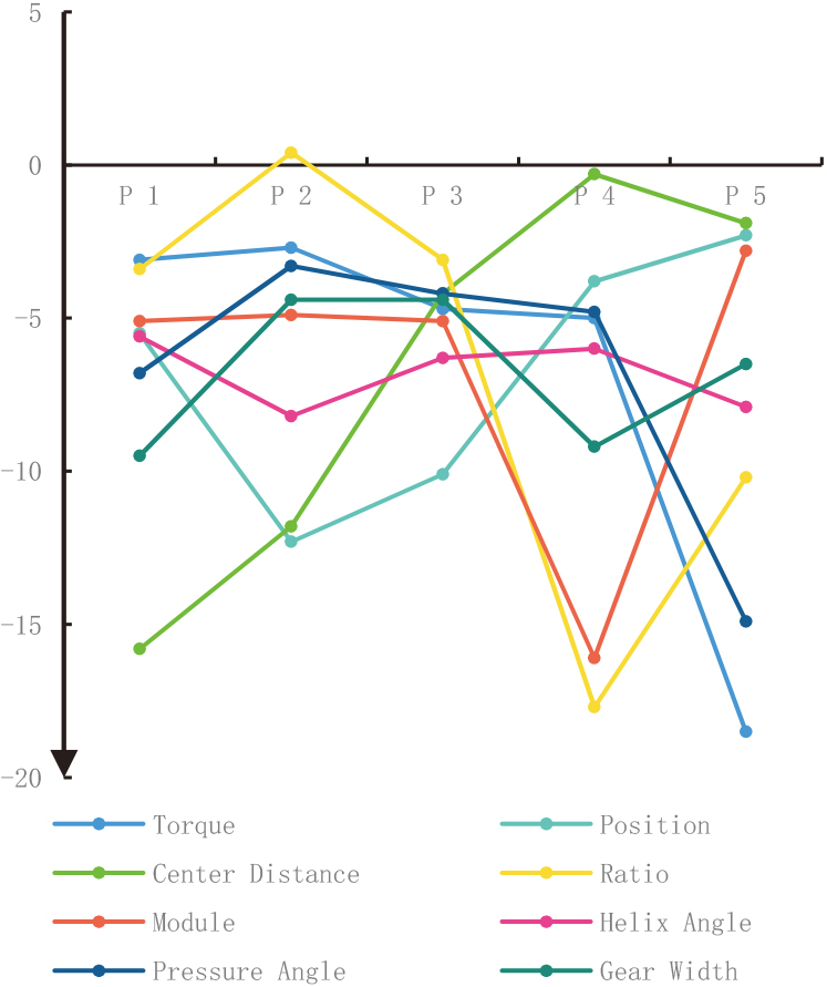
As depicted in Fig. 8, under the influence of different levels of various factors, the amount of profile crowning modification rises along with the increment of the transmission ratio and the torque, as well as the modulus. However, the amount of profile crowning modification grows down when tooth width, helix angle, and center distance grow up. The change in position causes an initial increase in profile crowning modification, followed by a decrease, but the overall variation range is relatively small.
Results of profile crowning modification.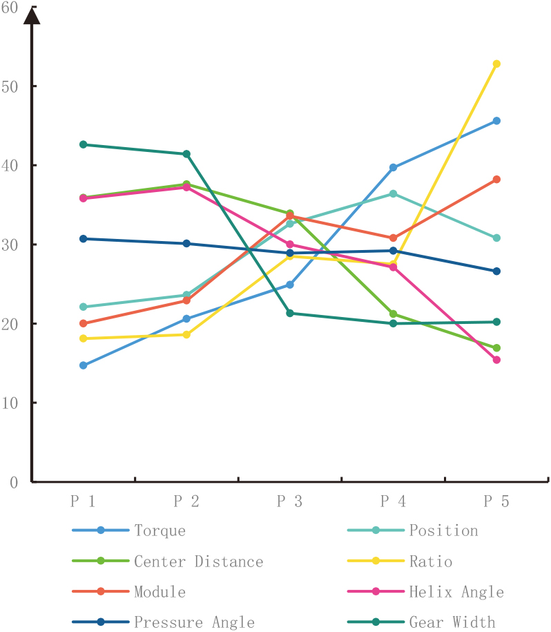
To explore the relationship between modification results and variables, it is proposed to develop a regression model based on support vector machine to reasonably predict the modification parameter results under the influence of these design variables.
Using “libsvm” toolbox in MATLAB to predict parameters of 4 types of tooth surface modification Three optimization parameters are available in the SVR module, namely:
Gaussian kernel function is employed in support vector machine regression analysis. Let e-SVR’s loss function
The training set randomly selects data from the 40 sets of orthogonal design experimental results above, and the test set has the remaining 10 sets. The training test and prediction results of the 4 modification methods are as follows:
Prediction model for helix angle modification parameters
As shown in Fig. 9, after training with 40 data sets, the squared correlation coefficient of the training set is 0.99947 and that of the test set is 0.83452. The final prediction model is then obtained, with optimized parameters c
Modification model for helix angle prediction.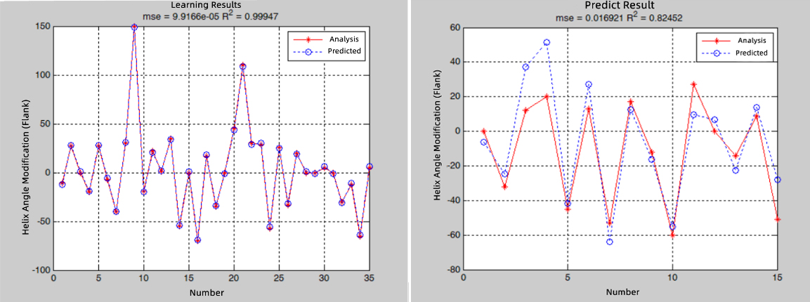
As shown in Fig. 10, after 40 sets of data training, the squared correlation coefficient of the training set is 0.99973, and that of the test set is 0.83550. The optimized parameters of final prediction model are c
Prediction model for helix crowning.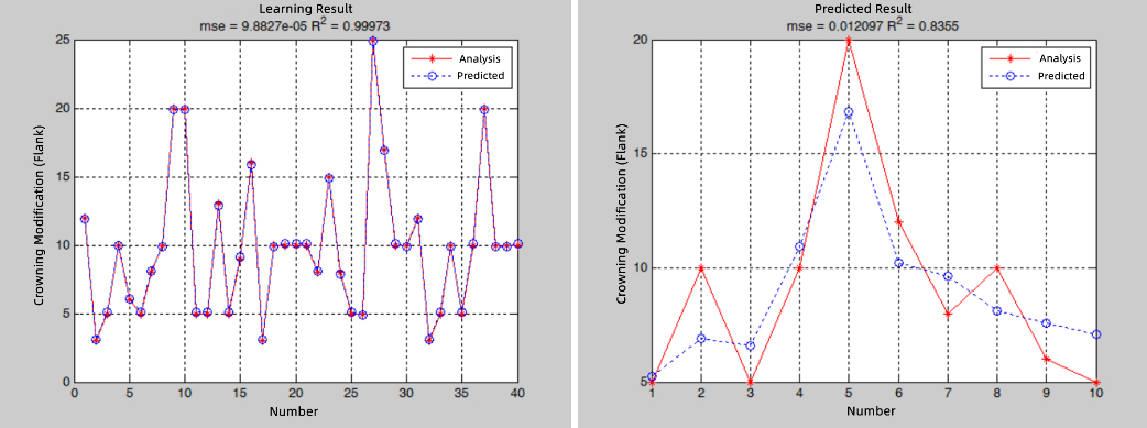
Prediction model for transverse profile slope.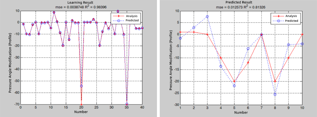
Figure 11 illustrates how the final prediction model is obtained after 40 sets of data training: the square correlation coefficient of the training set is R2
Prediction model for profile crowning modification parameters
According to Fig. 12, after 40 sets of data training, the squared correlation coefficient of the training set is R2
Prediction model for profile crowning modification.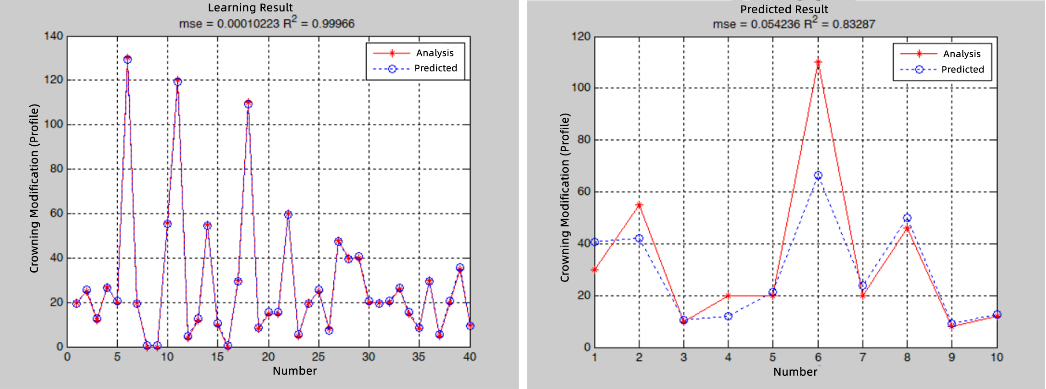
In summary, for the prediction models of 4 modification methods obtained from the design parameters and working state, the squared correlation coefficient of the training set is higher than 0.99, and that of the test set is also higher than 0.83, indicating that this model predicts with good accuracy and high practicality.
To further verify the engineering applicability of the prediction models of the 4 modification methods, the reducer of an electric vehicle was optimized with predicted tooth profile modification parameters based on SVM. The base samples and the optimized samples were tested on a high-speed motor test bench for comparison. The test bench is as presented in Fig. 13. The driving end of the test bench adopts K&A motor: the maximum test power is 388 kW; the maximum speed is 2000 rpm; the maximum torque is 530 Nm (@7000 rpm). The loading end adopts Siemens motor: the maximum speed is 3300 rpm; the maximum torque is 3700 Nm (@800 rpm); the control accuracy of steady-state torque of the system is
Comparison of test data
Comparison of test data
Test of the reducer of an electric vehicle.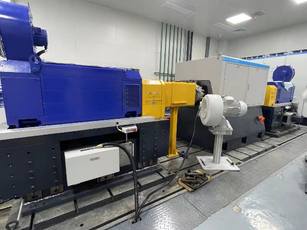
Table 3 illustrates the test results, parameters of base sample and optimized samples of the gear pair. Figure 13 shows contact spots after tests. Contacting surface of baseline part(left) is mostly on one side; however, that of optimized part(right) is more even, which indicates that the optimization effectively corrects the contact spots and maintains the center contact of the gear pair. Figure 14 illustrates the comparison data of the testing noise obtained with GRAS microphone. Results show that noise level of optimized part(red) is 3–5 dB lower than that of base part(blue) in the full frequency range, indicating an overall noise reduction for the reducer. The efficacy and efficiency of the modification parameters of the 4 prediction models are also validated by this test.
Contact spots before and after optimization.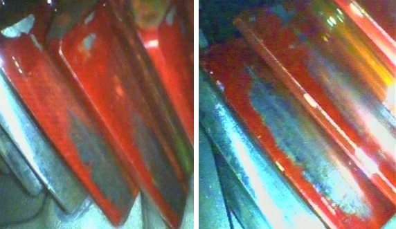
Experimental noise before and after optimization.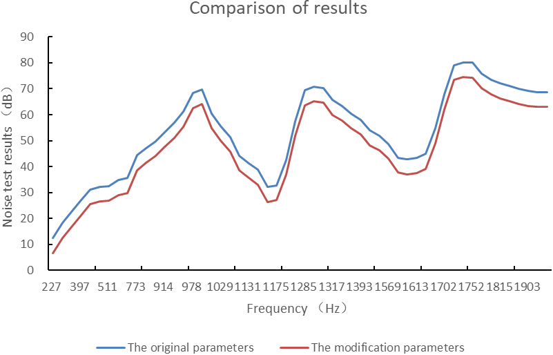
To explore the influence of gear pair design and working state parameters of transmission system on tooth profile modification, this paper employs the orthogonal design test method and considers 8 factors, including center distance, helix angle, pressure angle, tooth width, etc., to design 50 test sets, analyzing with built models based on test parameters and modifying according to unified standards. Via intuitive analysis, the influence of each factor on the 4 modification methods is determined, and prediction models of the gear system parameters based on each modification method are established using the support regression vector machine method. Results of both training sets and test sets demonstrate that the prediction model has a high precision. Test results also shows this prediction model has sufficient engineering applicability and can be used effectively to forecast tooth profile modification parameters.
This paper has not discussed the coupling influence of each modification parameters. This work will be conducted in the next study to present a more precise prediction model.
Footnotes
Project funding
Supported by Natural Science Foundation of Chongqing (CSTC2019JCYJ-BSHX0031); Sponsored by Science and Technology Research Program of Chongqing Education Commission (KJZD-K201803201); and the Doctoral Fund Project of Chongqing Industrial Vocational and Technical College (2022GZYBSZK1-01).