






Abstract
Engineering Planning is the primary task of underground engineering. The planning dimension of underground engineering still remains at the two-dimensional level, lacking a technical platform for processing and analyzing multi-dimensional and multi-source information. Especially due to insufficient information under hidden geological conditions, the quality of subsequent design and construction cannot be guaranteed. BIM
Introduction
The planning of underground engineering is not only directly related to the subsequent design and construction work, but also crucial for the safety and long-term use of the site. Bansal proposed that the engineering plan should not be developed in isolation-that is, without considering its immediate surroundings [1]. At present, the planning and design dimensions of underground engineering still remain at the two-dimensional plane level, and there is a lack of analysis and process methods for multi-dimensional and multi-source spatial information. The systematic and adaptive analysis of regional space is insufficient, making it difficult to adapt to future refined design requirements and constraints in complex environments. Therefore, there is an urgent need for innovation in planning and design technology, establishing an efficient and convenient auxiliary planning and design platform, integrating and analyzing the engineering itself and surrounding environmental information, in order to form a scientific and reasonable underground engineering planning and design scheme in multi-dimensional and multi constraint scenarios.
These requirements coincide with the characteristics of BIM (Building Information Modeling) and GIS (Geographic Information System). The construction industry needs to improve its refined management capabilities, strengthen transparent management throughout the entire lifecycle of engineering, reduce costs, and address issues such as tight construction schedules and high engineering quality requirements. BIM emerged in this context, and based on BIM technology, it can effectively help solve these problems [2, 3]. GIS has always been committed to the research of macro geographical environment, which can provide spatial query analysis, location services and other functions. At the same time, it provides special dynamic simulation for BIM, and provides decision support for BIM in the planning, operation and maintenance stages. BIM is an important data source for GIS, which can enable GIS to move from macro to micro level and achieve refined management. On the other hand, the integration with BIM data can enable GIS to move from outdoor to indoor, achieving integrated indoor and outdoor management. The comprehensive application of BIM and GIS can help us check the scientific rationality of engineering plans through spatial planning, collision detection, construction techniques, and virtual pre construction rehearsals [4]. In general, the fine modeling and the ability to endow rich attribute information with BIM technology, as well as the powerful data processing and spatial analysis capabilities of GIS, make it extremely significant to explore the method of combining the two in a real sense for the digital information development of underground engineering.
In recent years, many studies have applied BIM
This paper first introduces BIM
Overview of BIM
GIS
Overview of “BIM
” technology
BIM is usually translated as “Building information modeling” In fact, BIM
BIM, with attribute information that can be refined to the component level and has advantages such as high visualization, comprehensive building information, and good coordination. However, for macro sites, BIM has drawbacks such as poor modeling ability, large amount of model data, and long visualization preprocessing time. With the development in the past decade, the industry has formed “BIM
Characteristics of BIM
GIS
The characteristics of BIM and GIS each have their own advantages, BIM focuses more on the integration of the engineering project itself and its internal detailed features, which constitute relatively micro level data information. GIS focuses more on the integration and analysis of models with surrounding location and environmental information, and is often used to generate macroscopic information such as terrain. Therefore, it can be considered that BIM and GIS have a natural complementary relationship: the full lifecycle management of BIM requires the participation of GIS, and BIM will also explore the application fields of GIS, bringing GIS from the macro field to the micro field. The combination of the two can establish a comprehensive model based on multi-source multidimensional data integration. Using this comprehensive model to carry out auxiliary planning and design work can avoid the potential risks of traditional two-dimensional plane planning, reduce the subjectivity of the planning process, effectively improve the accuracy of planning schemes, expand the dimensions of engineering planning and design research, and endow various elements of the project with multidimensional attribute information.
Architecture of underground engineering auxiliary planning platform based on BIM
GIS
Underground Engineering often presents a comprehensive distribution of construction sites and lines, and relying solely on BIM cannot fully reflect the true information. GIS can display the positional relationship between underground engineering and the surrounding environment, but it cannot express detailed information within the project. Therefore, according to the BIM
Architecture of underground engineering auxiliary planning technical platform based on BIM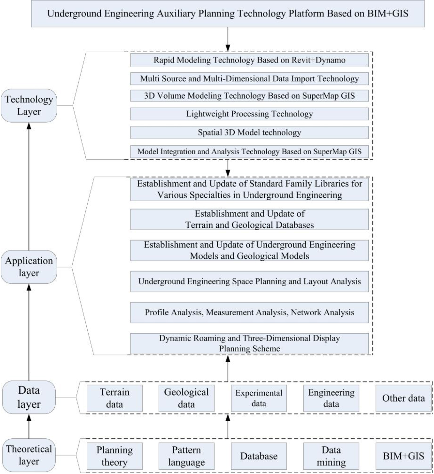
The platform can be divided into theoretical, data, application and technical layer. The theoretical layer is the foundation and support for the platform to achieve specific functions; The data layer mainly includes terrain, geology, experimental, engineering data, and other types of multi-source multidimensional data; The application layer includes the specific application scenarios of the platform, while also possessing scalability, allowing for the secondary development of corresponding functional modules according to actual needs; The technical layer includes the core technologies for implementing platform functions, such as rapid modeling technology for underground engineering based on Revit
Rapid modeling technology based on Revit
Dynamo
It is difficult to complete the modeling work of underground engineering solely relying on Revit. Dynamo has significant advantages due to its parameterized characteristics, which can solve various complex structural modeling problems. Therefore, the technology of three-dimensional rapid parametric modeling based on Revit
Building a professional family library for underground engineering requires sequentially constructing families based on the split component level models, while metric conventional models cannot automatically adapt to points on the spatial line or add automatic adaptation points. Compared to this, adaptive families can achieve parameter adjustment requirements by adjusting the properties and working surfaces of the family, and are more flexible in creating complex components. Therefore, adaptive family creation methods can be used when establishing component families. In this study, the professional component library of underground engineering includes the component library of construction engineering, Structural engineering and electromechanical engineering. As shown in Figs 2
Family of rectangular columns with corbels.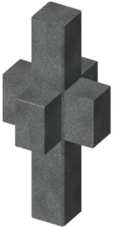
Cable trench tee family.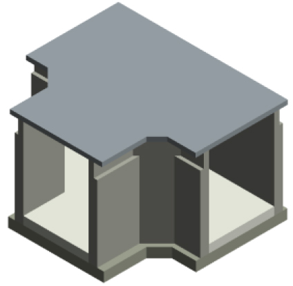
There is a lot of BIM software which the file formats are different. In order to solve the problems of data missing and incomplete information when BIM data is imported into the GIS software platform. This paper adopts export plugins and conversion tools to achieve seamless cross domain connection between BIM and GIS data interfaces. This technology has the following advantages: firstly, it can quickly import vertex and attribute information of BIM, ensuring the integrity of information. At the same time, it supports exporting by family classification and provides fast BIM grouping management; The second is to support efficient rendering of large-scale data and export models with multiple levels of detail; The third is to support the BIM 3D data model of induced topology closure.
3D volume data modeling technology
The development of 3D GIS technology is centered around data models. The 3D volume data modeling based on SuperMap GIS draws on the expression and analysis methods for discrete and homogeneous 3D solid spaces. The 3D volume data model represents 3D solid objects through a topologically closed, high-precision triangular network, and uses a half edge structure to describe the topological structure of each vertex and edge of the triangular network, as shown in Fig. 4.
Description of triangular network topology.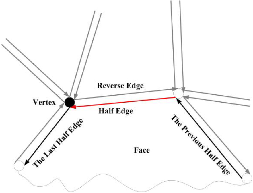
After Boolean operations such as intersection, union, and difference, three-dimensional objects are also topologically closed and remain three-dimensional. The 3D volume data modeling supports calculating the volume and surface area of the model, and intercepting any cross-section of the model. Transforming BIM data structure, including spatial data and attribute data, into a 3D volumetric data model, utilizing the analytical and computational capabilities of the 3D volumetric data model, the BIM data has been analyzed and calculated on a GIS platform.
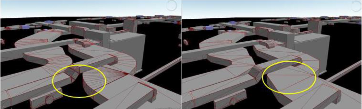
Lightweight processing technology, which involves deleting or simplifying certain skeletons of the model. The level of precision required for BIM data varies in different application stages. Therefore, the model can be lightweight according to actual needs. Lightweight processing techniques include: extracting shells (separating shells and interiors), simplifying triangulation, simplifying sub objects (deleting), deleting duplicate vertices, calculating (deleting) normal, model splitting, model merging, and so on.
Simplify Triangulation. BIM is a high-density model that can accurately and exhaustively display the internal and external elements of buildings, so its large amount of data often leads to poor 3D scene performance of BIM models. By using triangulation simplification technology, the effect of simplifying BIM models can be achieved, reducing memory usage and meeting the performance needs of large-scale data.
Triangle simplification. Delete sub objects. For BIM models, the purpose of improving 3D scene performance is achieved by deleting useless sub objects. For example, the “door” object is a single door object with 980 vertices and 920 triangular faces But in reality, these components do not have significant value for actual work. Therefore, deleting or simplifying these skeletons was adopted to achieve the objective of model lightweight.
Model integration flowchart based on SuperMap GIS.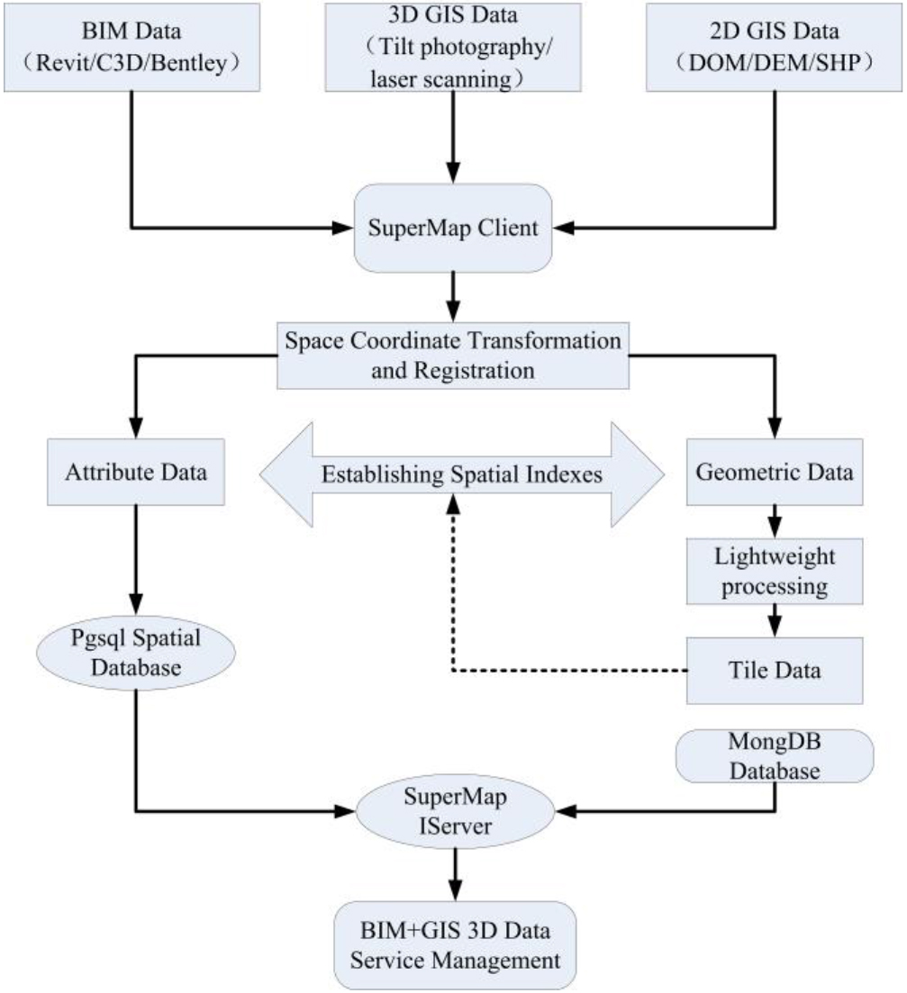
The Spatial 3D Model (S3M) solves the problem of efficient transmission, exchange, and visualization of massive and multi-source 3D spatial data in both online and offline environments. S3M is a data format suitable for the transmission of massive 3D model data. Through an efficient, easy to expand, and collaborative data specification, it can meet users’ needs for 3D data transmission and analysis at different terminals (mobile, browser, desktop). By generating BIM data into S3M cache, the data transmission speed and terminal visualization effect have been improved.
Model integration and analysis technology
The integration of BIM and GIS models is mainly achieved through data format conversion, and then integrated on a GIS platform. However, in the respective systems of BIM and GIS, their data formats and storage encoding forms are completely different, and there are obstacles to achieving data exchange between BIM and GIS [17]. On the other hand, GIS platform has significant bottlenecks in rendering frame rate, image quality effects, interactive actions, which is difficult to meet the current industry’s demand for 3D interaction. The emergence of the game engine Unity has made up for the shortcomings. Considering that SuperMap GIS can directly provide Unity plugins. Therefore, this paper conducts integrated processing and analysis research on BIM
The main process includes: first, importing 2D and 3D GIS data directly into SuperMap iDesktop; Then, the BIM model data is transformed through plugins and imported into SuperMap iDesktop. The imported data is then transformed and registered in spatial coordinates to ensure the correctness of spatial positions of data from different sources; Then, perform lightweight processing on BIM data; Subsequently, the BIM
Based on SuperMap GIS platform, Spatial analysis and auxiliary planning and design centering on BIM
Simulation analysis of underground pipe gallery engineering
Establishment of engineering and geological models
This section takes an underground engineering project as an example for simulation analysis. Firstly, using preestablished professional standard family library of underground pipe gallery engineering, and then in view of the overall requirements, the model was established in the form of “building blocks”, which as shown in Figs 7
Overall engineering information model of underground pipe gallery.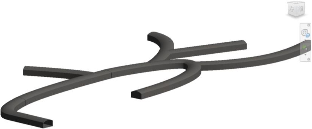
Internal engineering information model of underground pipe gallery.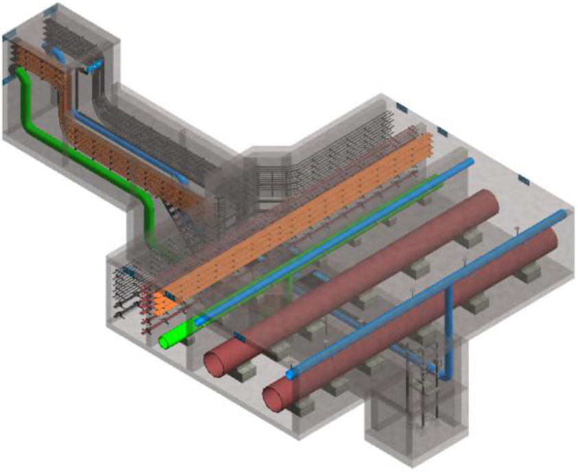
Through the rapid modeling technology based on Revit
3D geological information model of underground engineering site.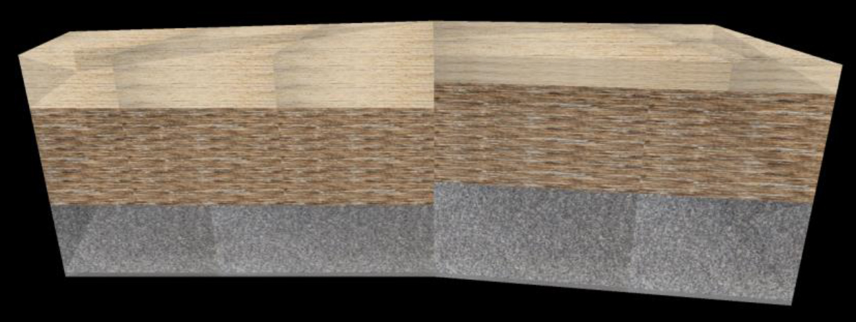
Through the establishment of an underground pipe gallery engineering model and a three-dimensional geological model in the previous section, and based on the key technologies in the platform’s technology layer, the spatial coordinate transformation and positional relationship registration of an underground pipe gallery engineering information model were achieved. At the same time, in order to improve operational efficiency, lightweight processing was carried out on the imported data, such as simplifying the number of triangular patches of the data, Then, the transformed and registered BIM
The BIM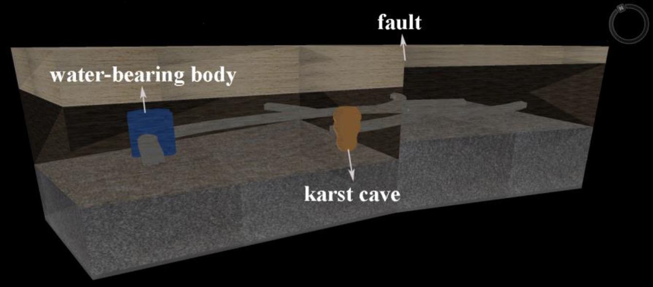
From Fig. 10, it can be seen that some engineering structures directly pass through water-bearing bodies and karst caves, while the entire project passes through fault. If subsequent construction is carried out according to this planning and design, it will undoubtedly bring significant safety hazards. Therefore, based on the unfavorable geological in the geological model, the planning layout of the project has been adjusted. The spatial relationship between the optimized information model of an underground pipeline gallery and the unfavorable geological is shown in Fig. 11.
Spatial relationship between optimized model and unfavorable geological structure.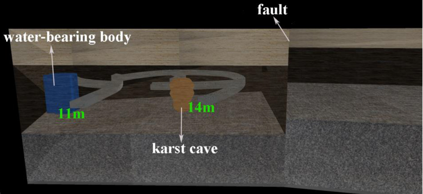
From Fig. 11, it can be seen that the optimized underground pipeline gallery project is about 11 meters away from the water-bearing and about 14 meters away from the karst cave without affecting safe use conditions, and completely avoids faults, effectively solving the adverse effects of unfavorable geological structures. In addition, research can also be conducted on integrated models, including height testing, area measurement, volume calculation, and sectioning analysis.
Through the engineering simulation analysis, the results show that in a three-dimensional geological environment, by dynamically querying and analyzing geological information, it is possible to determine the reasonable spatial layout and scope of the project based on the three-dimensional geological model. By analyzing the three-dimensional spatial conflicts between geological and engineering entities, not only can the three-dimensional situation and geographical environment correlation of the planning project be clearly displayed, and it has further improved the intuitiveness, scientific, and rationality of planning and design work. Based on the research method in this paper, the planning and design can be quickly and dynamically adjusted according to the unfavorable geological conditions predicted in advance to ensure the safety and economy of underground engineering.
The informatization and intelligent development of underground engineering is the trend of the times. To address the current problems in the planning stage of underground engineering, this paper explores the innovative direction of underground engineering auxiliary planning and design technology based on BIM
A preliminary underground engineering auxiliary planning and design platform has been established, with a technical architecture including theoretical layer, data layer, application layer, technical layer, and data foundation base; In the technical layer, the focus has been on the rapid modeling technology based on Revit
Through BIM
The next step will be to build a multi-objective decision-making model that comprehensively considers factors such as safety, economy, and environmental protection based on this platform and survey big data. An intelligent planning method that combines local computing and global situational awareness will be established, and expert systems and artificial intelligence technology will be used to plan engineering construction projects more comprehensively, systematically, scientifically, and reasonably As a part of the engineering construction lifecycle, the BIM