






Abstract
Automotive embedded applications are gaining widespread importance worldwide. Almost every car is equipped with hundreds of software-enabled technologies which are expected to have a drastic spike in the coming years ahead. With the advent of more and more automatic and autonomous techniques, there arises an extensive requirement of applying latest development and testing strategies. Apart from using single traditional V-Model, the design and test cases are generated based on more advanced double and triple V-models. The front panel of one of the autonomous car systems is designed and more refinement is obtained for optimum test path generation using prefix graph algorithm and edge-pair coverage criteria.
Introduction
Despite the compliance of model-based testing with the automotive industry, it tends to be overlooked and done in an unsystematic manner [1]. Structured and fully organized system model based testing is still missing. There is an exponential rise in the use of embedded software in systems such as automobiles. The share of software enabled technologies and innovations have drastically spiked from 20 to 85% and are still growing. Research predicts that now software will dominate more than 90% of automotive systems in few years [2]. A study reports [3] that around 24% of total software budget and 32% of the project management budget is assigned to testing processes, but due to extra pressure of completing project before deadlines, the testing is likely to be reduced and quality is at stake.
A NIST (National Institute of Standards and Technology) report stated that inadequate design and testing methods cost US economy around $60 billion annually in the form of extra testing, redesigning and mitigation costs [4]. Today software is a crucial part of automobile development. It is predominantly used in functionalities such as driver assistance, vehicle dynamics control, infotainment and other active and passive safety systems. With more usage of software in automobile implementation, and increase in complexity of systems, the possible challenges arising due to system failures have increased [5]. Car software architecture is becoming more and more intricate since carmakers outsource the design of software modules to third party automotive electronic suppliers. Due to increasingly large size of software embedded in these products, more time has to be spent on verification and validation of such systems with improved model based techniques and processes with refined architectures [6]. Model-based testing process as shown in Fig. 1 is a test generation paradigm where the system under test is illustrated with a formal modelling method such as finite state machines, Markov chains or other UML artefacts like behavioral and structural diagrams for automatic generation of tests [7]. MBT considers software specifications and customer requirements as a fundamental base for formal modelling and test cases are extracted from these models. Model-based testing can also be regarded as one of the the automation of black-box test designs [7].

Traditional Vs model-based development [7].
The escalating complexity and demand for highly qualitative applications, having small production times, led organizations to invest more on automated test suites generation, and fascinated the tester’s inclination on model oriented testing methodologies and tools [8]. Testing case studies report 20 to 85% effort reduction on executing model based testing approaches [9]. Abstract tests are produced using MBT approach which must be transformed into executable tests by the test engineers. MBT is associated with several advantages with respect to manual testing or code-based testing [8] in terms of: Cost-savings and effort reduction. Models are excellent source of communication with the stakeholders proving to be effective in managing the complexity of the system. Model based testing provides inexpensive mode of validating the iterations in a software leading to easier and faster production of an application. Finally, the greatest advantage is that testing starts in advance during the software engineering life cycle.
This paper has been divided into six sections. The next section discusses about the background and the related work in the field of automotive domain. Section 3 explains the proposed research methodology and Section 4 and Section 5 describes the Modeling framework and a case study on adaptive cruise control system in detail. Using the framework, efficient test paths are generated and finally Section 6 concludes and discusses the future work using the methodology described.
Research work conducted at VTEC (Volvo Technology) [5] on analysis of Software Testing Methods and Tools provides very surprising results and observations regarding the techniques of testing followed to assure quality of automotive software. There are no clearly identified standard approaches for quality assurance of systems and most of them are relying on random, ad-hoc methods of testing. Figure 5 depicts around 22 different set of tests that are used in automobile industries. On the basis of interviews conducted on 8 different teams in different automotive companies the graph is shown in Fig. 2. The graph represents the popularity of the different testing methods and techniques among the various project teams. Unit testing was fairly popular practice as it was reported by 7 teams, and 5 teams reported usage of integration testing, 3 teams which did not perform integration testing either had an external testing team or testing was performed by the customer. In case of two project teams the interview respondents mentioned that the projects they are working on are in alpha stage and requirements are not strictly defined and therefore software testing is not very rigorously applied. It was also noticed that all the teams with ad-hoc testing approach did not have a dedicated testing team. Teams with ad-hoc testing approach had external software testing team, and another team had small team size, so the team members were responsible for performing multiple roles.
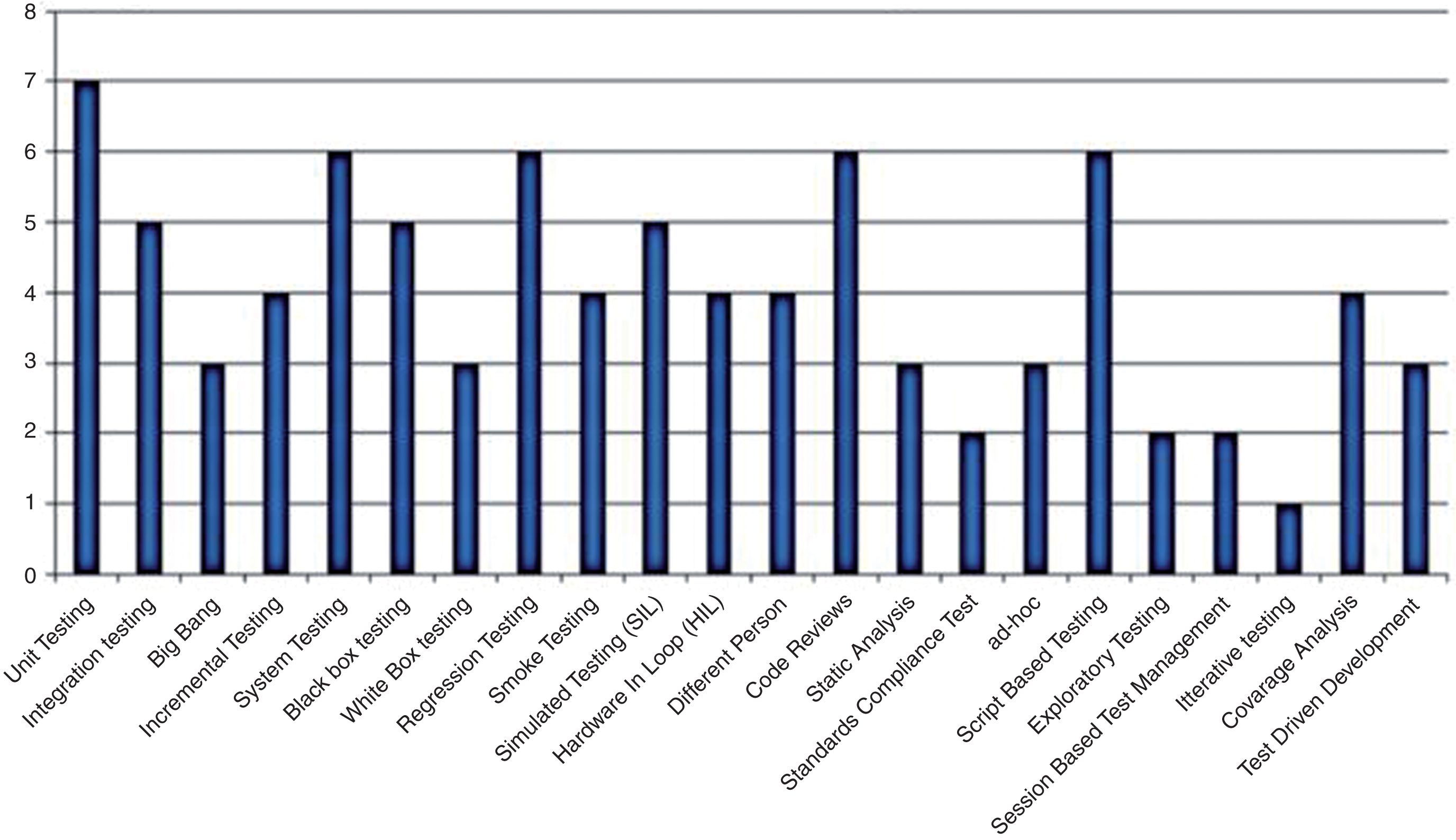
Response towards various software testing activities [5].
In order to ensure that the system will behave as expected under any operational circumstance, formal verification and validation procedures need to be added to the actual development process. In the research paper [9] the authors have proposed an iFEST (Industrial Framework for Embedded Systems Tools) process and platform for embedded systems design with model-based testing using MaTeLo, and model checking time-dependent requirements with the Uppaal tool, as means of increasing the confidence in the system’s behavior. The authors concluded that Model-based techniques help in tackling the design challenges, whereas methods such as simulation with tools like MATLAB/Simulink can be employed for analysis. Weissleder et al. [10] in their research reported a pilot project to apply MBT in embedded software domain. They have concluded that if Model based testing is initiated well in the project’s starting phases then there is an instant advantage as time for designing the models is usually lesser than manual developing of the test cases. Technique used is manually designing the UML state machines in a software Enterprise Architect by sparx systems and then importing this model in conformiq designer tool using XMI 2.1 interchange format.
Another very important research [11] funded by U.S. Army Aviation and Missile Research Development and Engineering Center (AMRDEC) highlighted the major causes of error inception right during the product initialization phases. This has been elaborately depicted in the following Fig. 3 of V-Model.
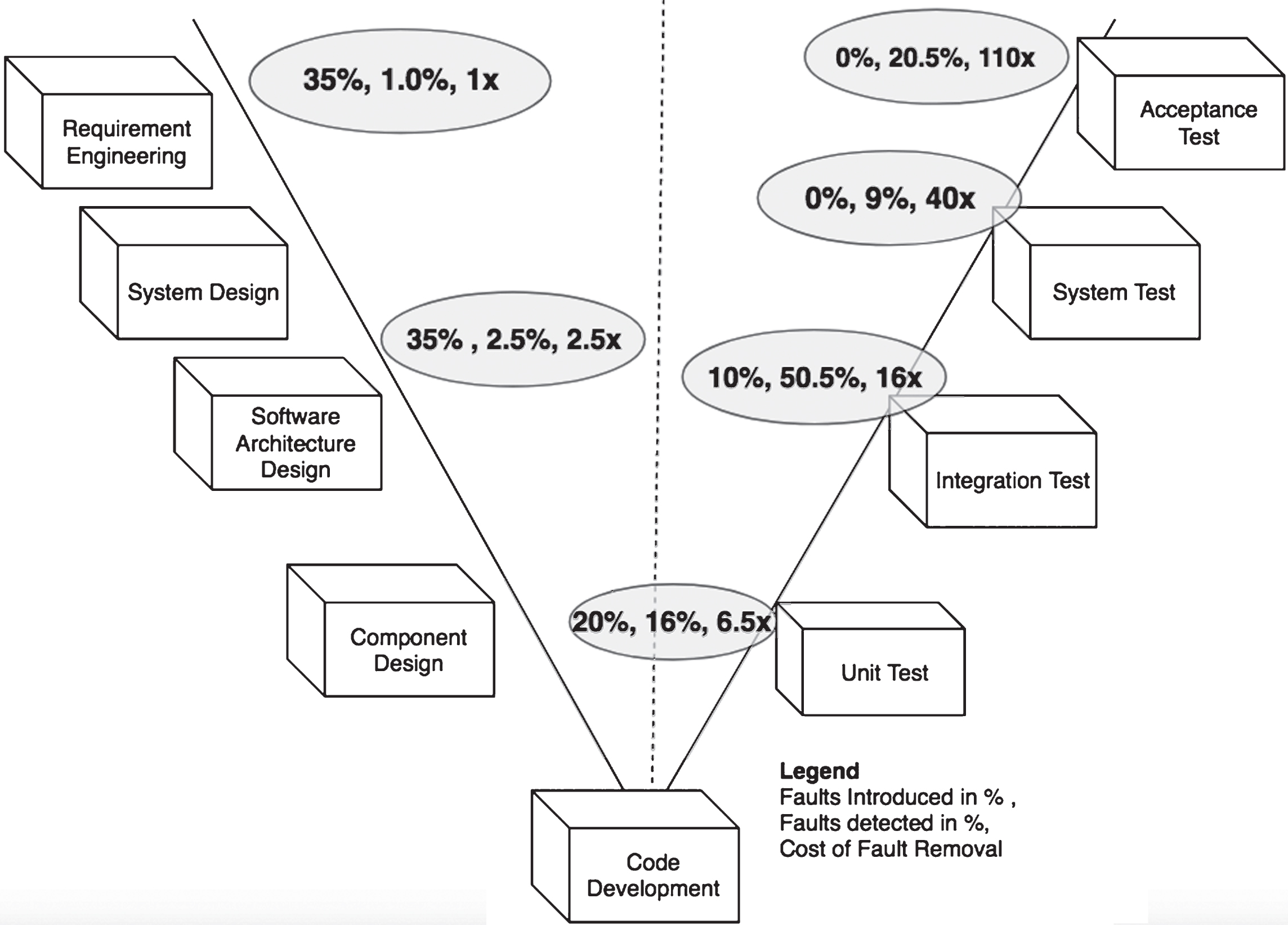
Error propagation rate in simple V-model [11].
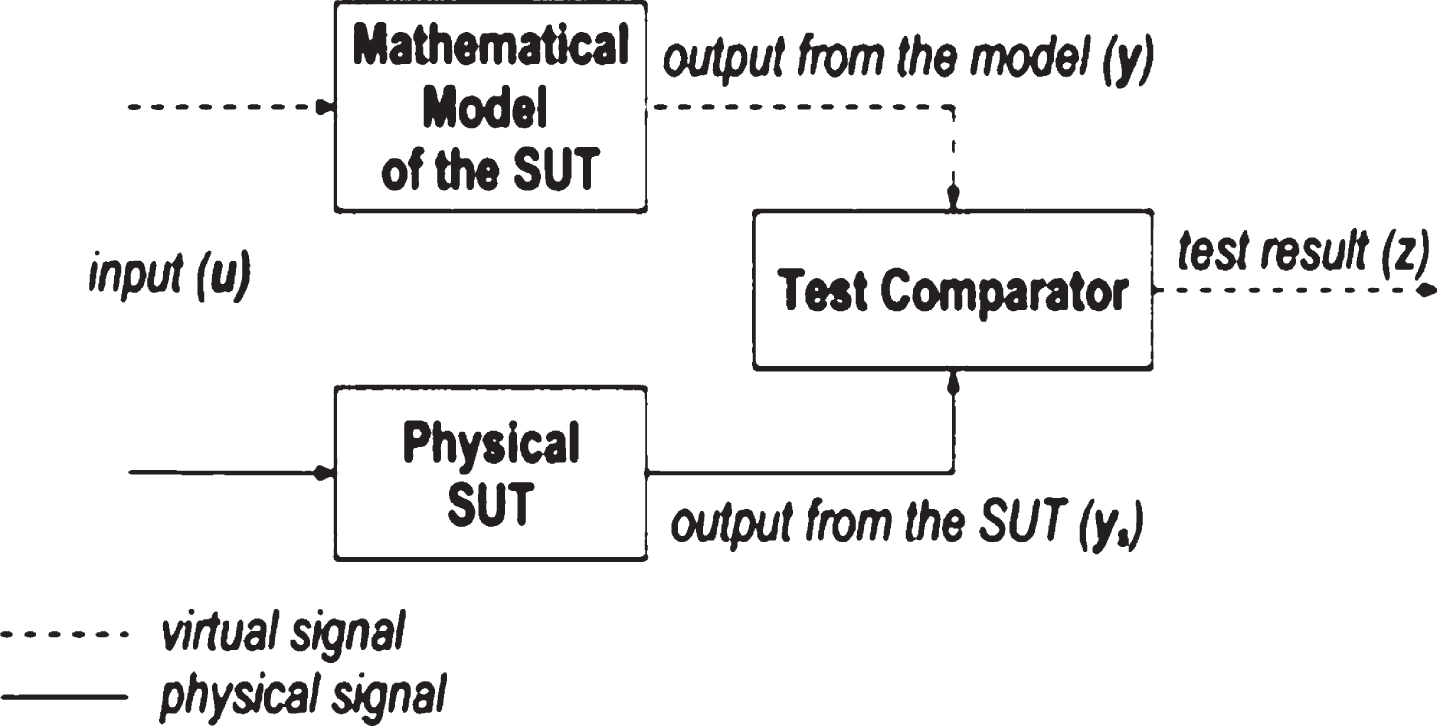
This study has provided very striking facts and figures. Research claims that 35% of faults are introduced during requirement engineering phase but only 1% are detected where very less rework in terms of effort and cost has to be incurred. Also, during software architectural design phase, 35% errors gets introduced, out of which hardly 2.5% are detected. The downward Portion of traditional V-model shows development phases. The errors occurring in coding phase are merely 20%, out of which 16% are detected. Hence, the estimated cost removal is shooting up constantly in each subsequent phase of V-model posing a serious challenge. A research work at Delphi, Poland depicts two different models [12] derived from User specifications. The models are Test Model and the Implementation Model. The two major activities of software engineering and test Engineering run in parallel. This approach has been applied on different types of automotive projects. Execution of test cases and generation of test reports is carried out by a Test Harness. A test comparator is also used to compare the actual and expected outputs. If there occurs a failure, then either implementation model or test model needs to be redesigned. The model used in the research is shown in Fig. 4.
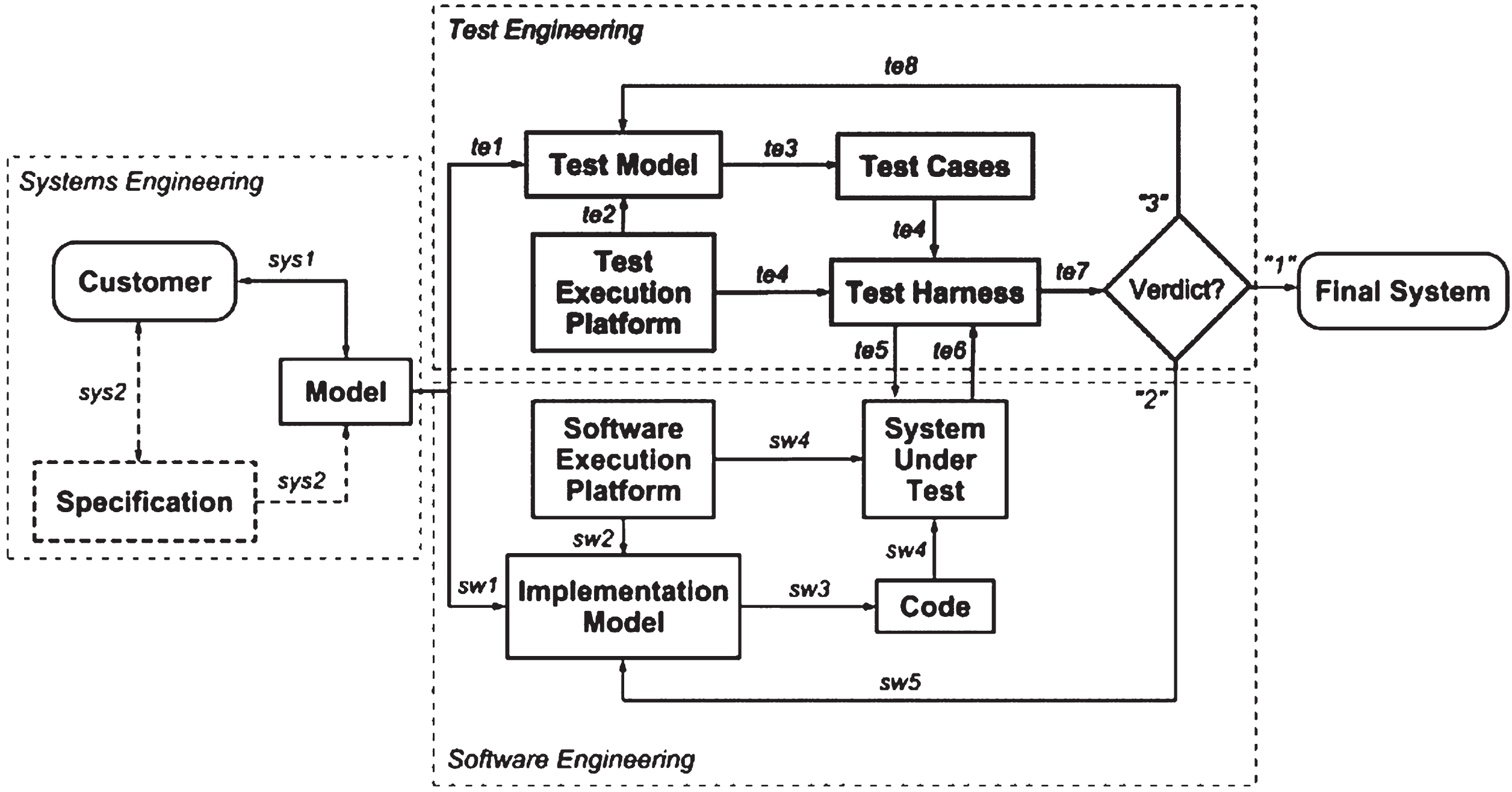
Test model and implementation models [12].
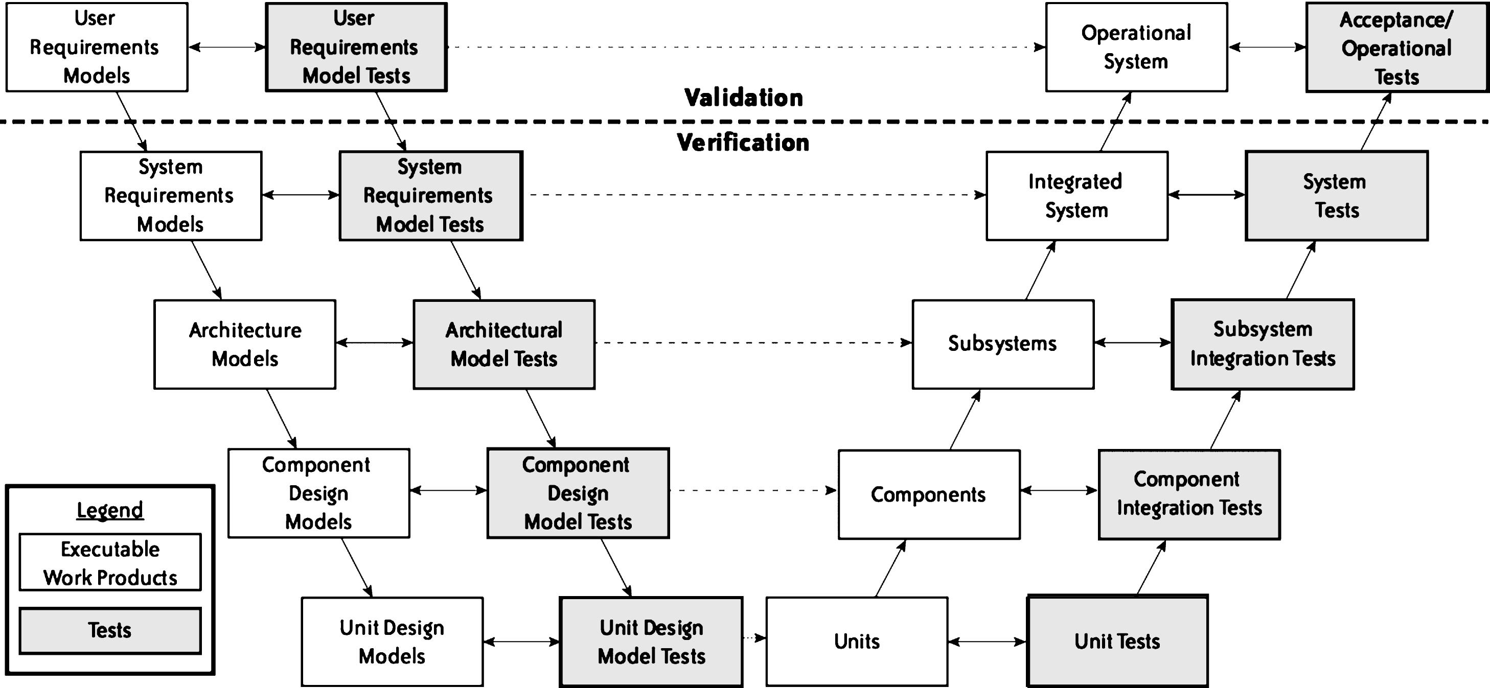
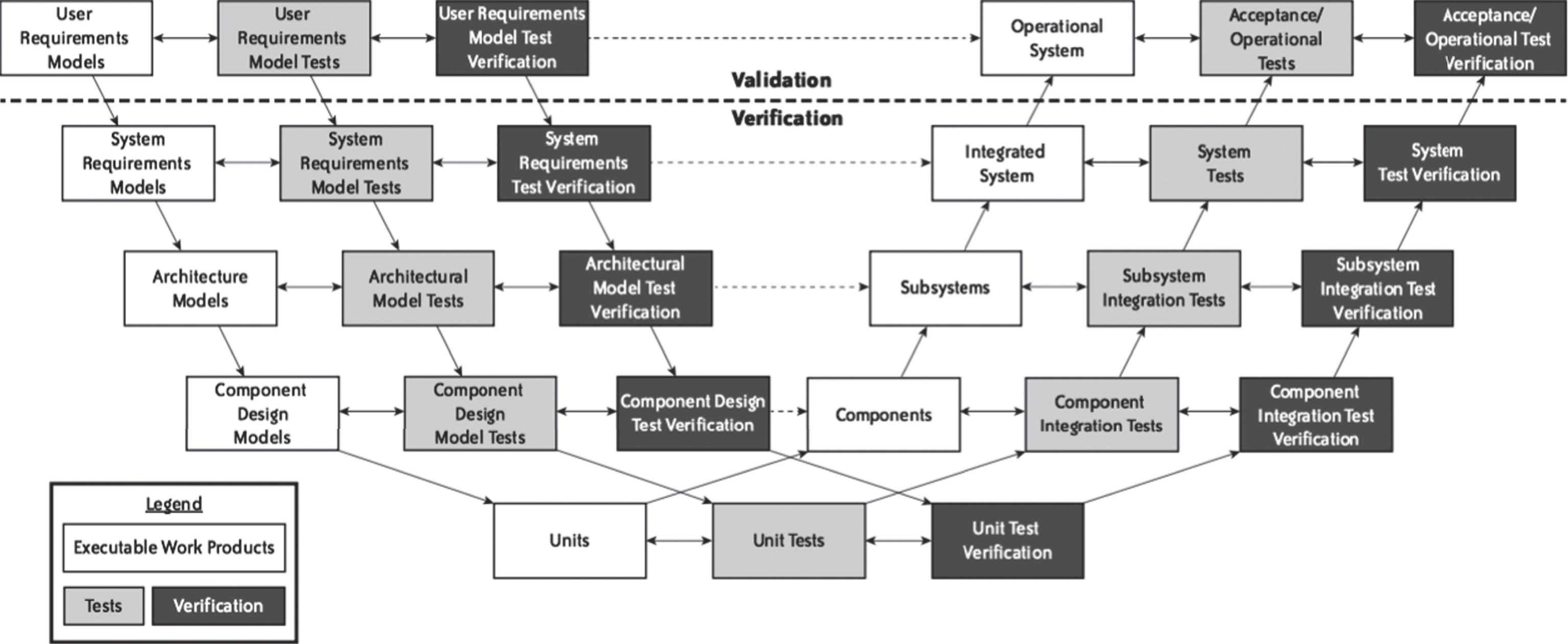
The V-model does not very well represent the system engineering activities from tester’s perspective. Therefore, a more thorough and a comprehensive V-model should be used for better capturing of system engineering aspects. It is very critical to test the executable requirement models, architectural models as well as unit design models. The two detailed versions are double V-model shown in Fig. 6 and triple V-model depicted by Fig. 7. There are total 5 rows in these models for performing validation and verification tasks [13]. The upper row is a validation row to validate if the system meets the requirements specified or not. The lower layers are for the verification purpose. Models are built in each phase which are tested using different model tests. Similarly, in triple V-model, same activities are conducted with an additional model-test verification layers for each phase.
Double V-model [13].
Testing comparator [12].
Use of code generator for validation [18].
In [14], the authors have derived Model Based Tests by using EAST-ADL (Advanced Description Language) technique. ADL is a standard used by the automotive industries. Automatic test generation is done and are validated against python test scripts. Authors have applied this methodology on a case study on ABS (Anti-Lock-Braking) systems of car and have received improved results than previously used methods. Two major tools have been used, i) ViTal and ii) Farkle for abstract test case generation and automatic python test script production respectively. Main focus of the research is to test feasibility of combined EAST-ADL approach with timed automata’s test case generation.
The research work by Bringmann [15] provides us extensive insight of MBT as this is a domain on which we plan to focus more, and they have made use of MATLAB/Simulink models in their work, which is also of particular interest to us. The authors present their test tool TPT- Time Partition Testing, which explores the complexity of Automotive software. The authors frame their work by describing the growing trend of containing more and more software estimated over 90% within the next decade. From there they go on to motivate the use of MBT for its ease of understandability in such an interdisciplinary field, stating that it improves communication within, and between, different levels of design.
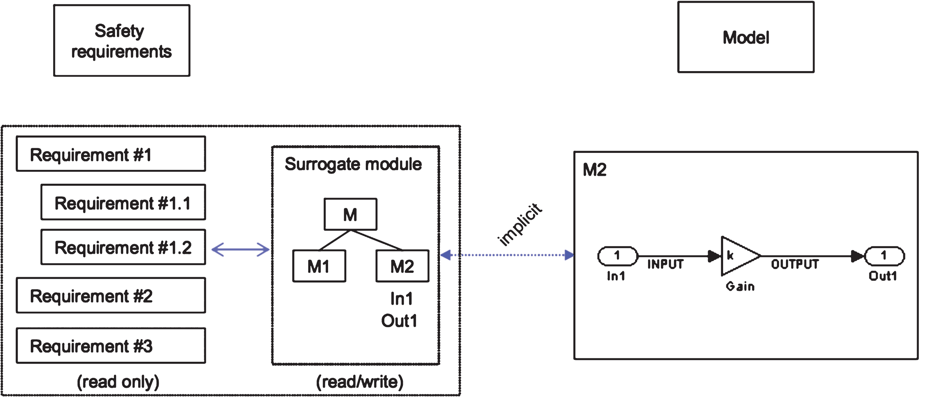
Research [16] discusses a new approach of dynamic model testing where major chunk of testing is covered by verifying the models only and executable models serve as basic source of information for testing and code generation. The authors have used a surrogate module to link requirements with the model elements which is shown in Fig. 8.
Triple V-model [13].
This paper [17] introduced TCG, an MBT tool for functional and statistical tests. It uses as input both LTS (Labelled transition systems) and probabilistic LTS models. The main contributions are the implementation of a variety of techniques in only one tool, including ones that have not been implemented in similar tools, and the introduction of a new selection criteria, the minimum probability of path. A case study is shown where the tool LoTuS is used to generate and select test suites for a distributed system. LoTuS is an open source lightweight tool for graphical modeling of the system behavior using LTS. It provides an interactive and simple way for the creation, composition and manipulation of LTSs [17].
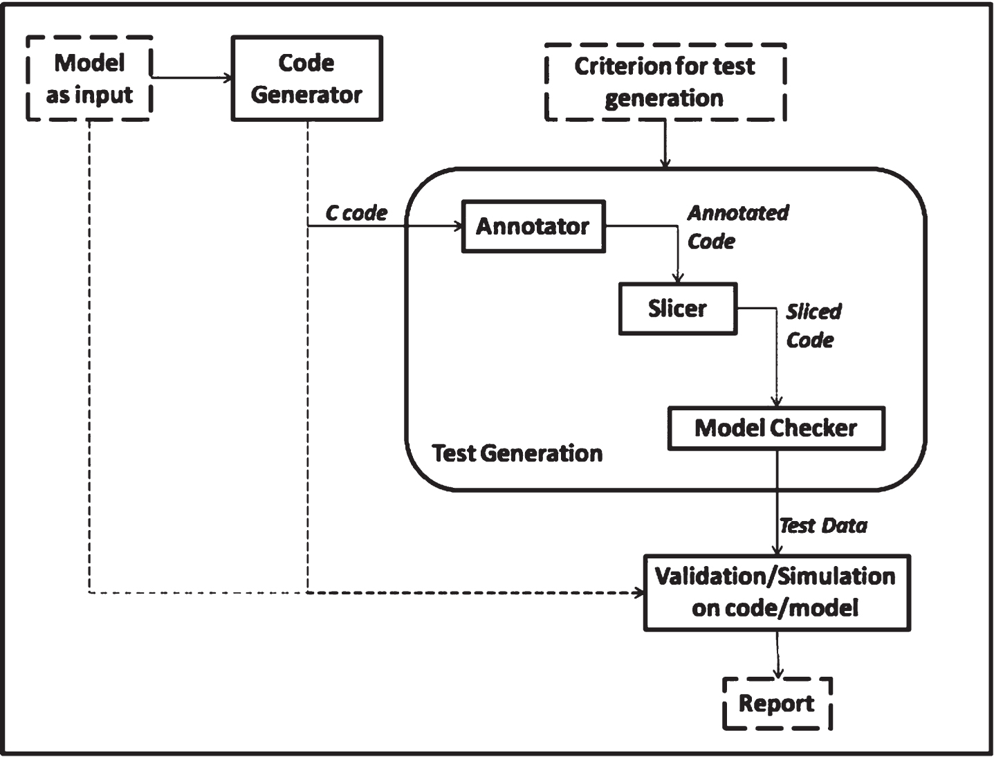
The research work [18] establishes the results of effective test case generation from models not directly but through the use of C-code in automotive domain. The Fig. 9 uses a model checker with a slicer to generate test data. The study provides tough arguments to transform the model elements into C language for better test management. The generated C-code is sliced using static analysis. Test data is generated from sliced c-code. The MC/DC coverage criteria is used for overcoming the problem of scalability.
Linking requirements with model [16].
Our Research Methodology will be focusing on the following process for design of models and generation of tests.
Specification capture
Using Simulink or UML modelling Tools such as LabVIEW, StarUML, Rational Rose and Modelica, Specifications and requirements are modelled.
Refinement of specifications
Using MATLAB/SIMULINK LIBRARY and UPPAAL Model Builder, specifications are refined. Refinement involves converting the abstract design into lower level design depicting implementation details.
Co-simulation
Using Simulation Inspector by Simulink, verification of refined design takes place with respect to original specifications of first phase. In the process of co-simulation, individual subsystems are architecturally modelled at component level or unit level in distributed way.
System-level description
Using Esterel and State Machines [21] of NI LABVIEW, a complete Functional model is created with implementation details.
High-level behavior synthesis (HLS)
The tools such as Vivado/Xilinx can be used to implement synthesis step to effectively build an optimized architecture.
Simulation
It will be done by MATLAB/Simulink Tools by first Running the Simulation and then analyzing the simulation results by viewing and Debugging the results.
Verification and validation
Using MATELO and Uppaal final verification and validations are done by exporting the model in the form of XML files and using Test Coverage Criteria using Automated Tool Set (Explained using block diagram below).
Model– based design and testing framework
A model-based design and testing framework depicted in Fig. 10 has been designed which provides detailed steps to generate test cases and also test evaluation. The foremost step is to build a model. Later, modelling, analysis and debugging the simulations is performed. For generating tests, different model checking techniques can be applied. This methodology provides advantage of providing executable test scripts, code and test model.
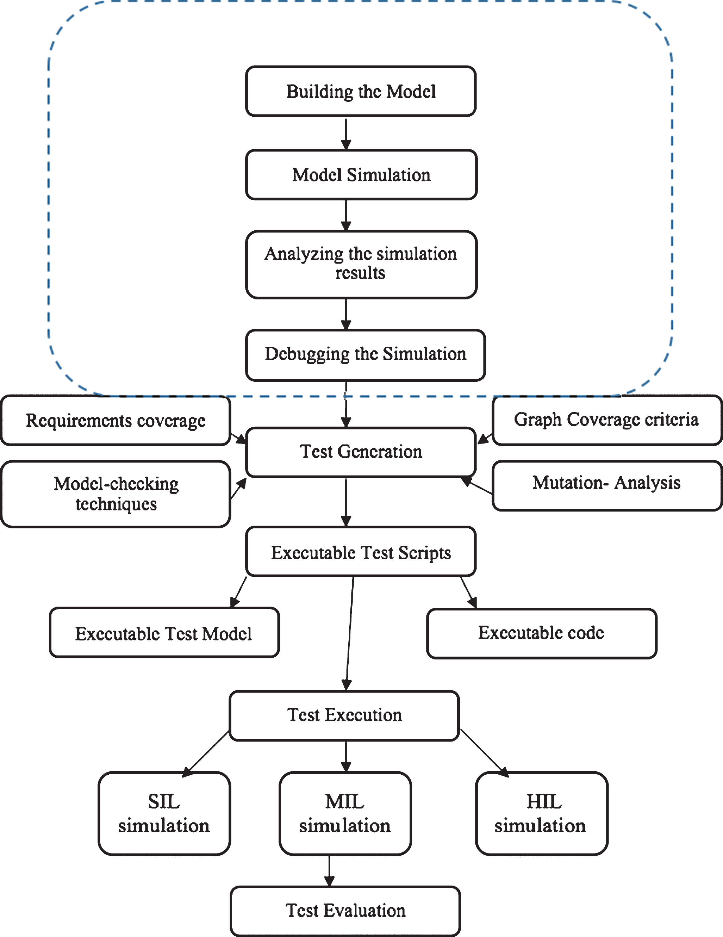
Modelling framework for test case generation.
A Cruise Control architecture is shown using LabVIEW software where Fig. 11 represents front panel view interface. When this model is executed, we can drive the vehicle manually first and then set the accelerator slider to the desired speed. Three buttons of ON, SET and RESUME are provided on the panel. When ON button is clicked, CCS (cruise control system) is set to initial state/mode. After this, set button is pushed which sets the analog speed indicator at a speed matching with accelerator slider.
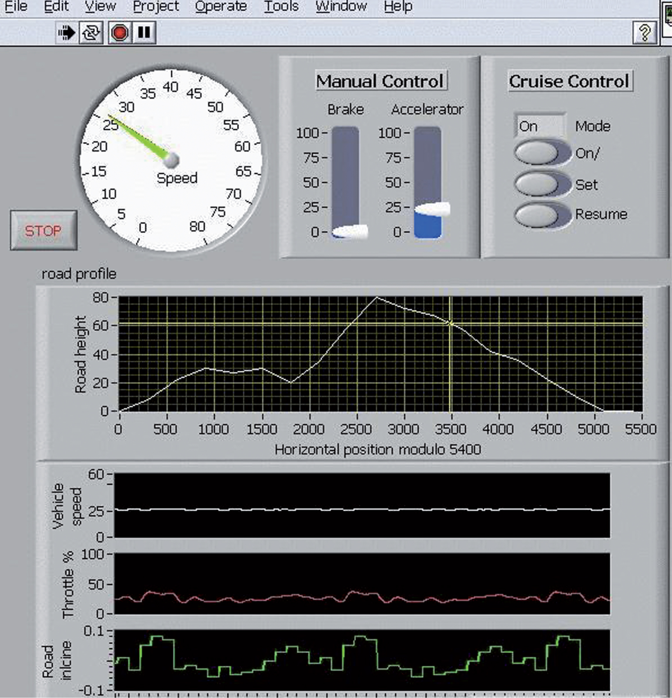
CCS front panel interface.
Road inclination, throttle and speed of vehicle are also shown in this front panel to keep the track of variations and adjust the speed accordingly. The following hierarchy chart in Fig. 12 describes the implementation details of three different subsystems- of cruise control, vehicle and road. During this phase, simulations are shown.
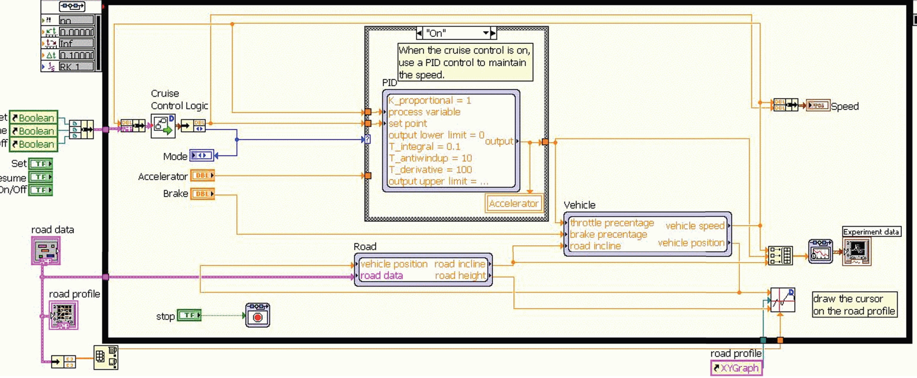
Hierarchy chart for CCS.
The hierarchy chart can easily be converted into statechart machine in LabVIEW [23] consisting of four major states: ON, OFF, IDLE and SET. The CCS state machine diagram is shown in the Fig. 13.
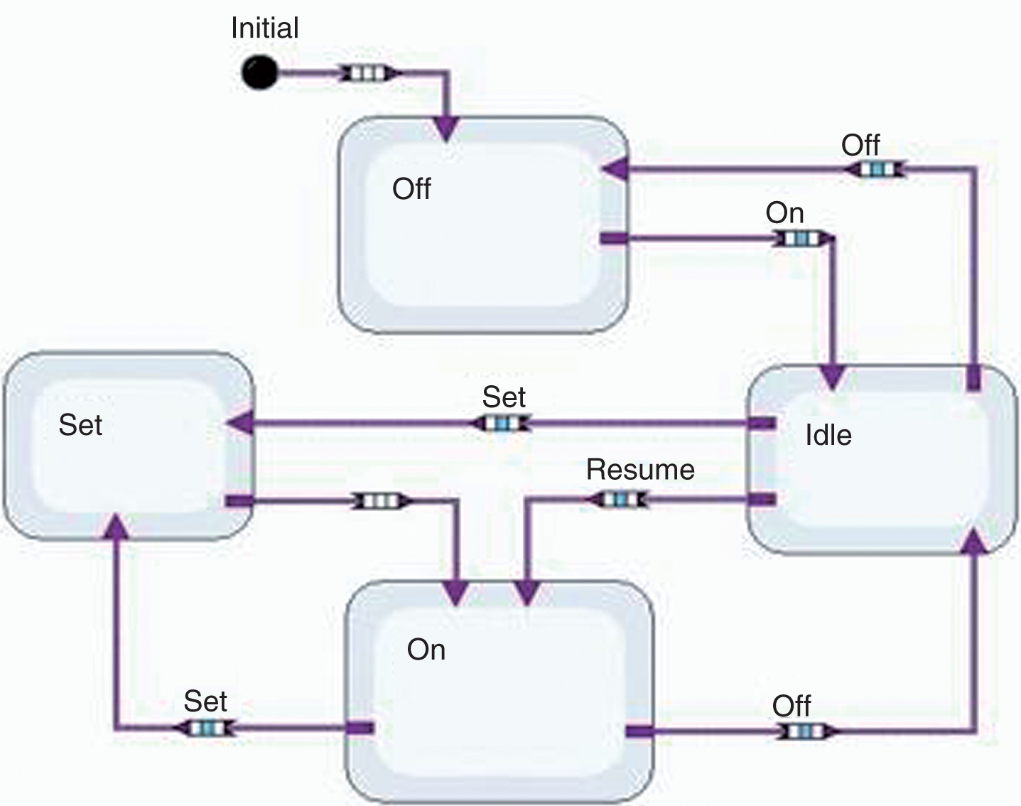
CCS logic state chart machine diagram.
Now using the Simulink tool [20, 22], a more refined version of the hierarchy chart in Fig. 14 is created including the implementation details involved in the process. This Model will allow us to generate test signals as shown in Fig. 15.
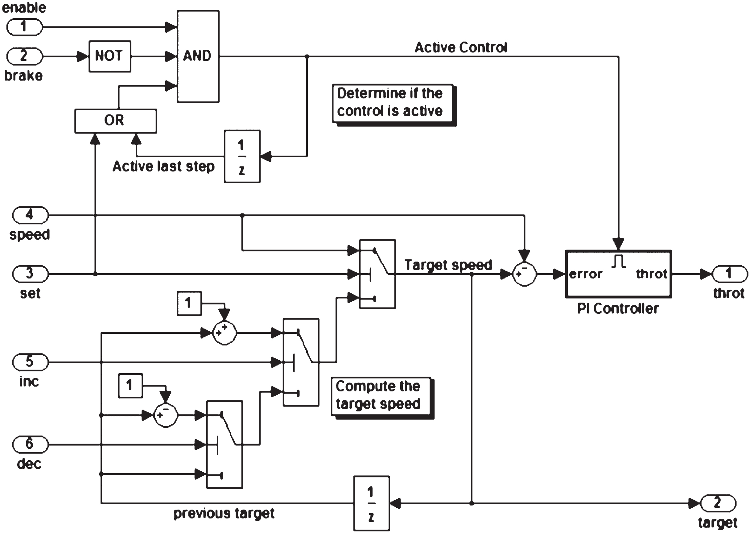
Refinement model.
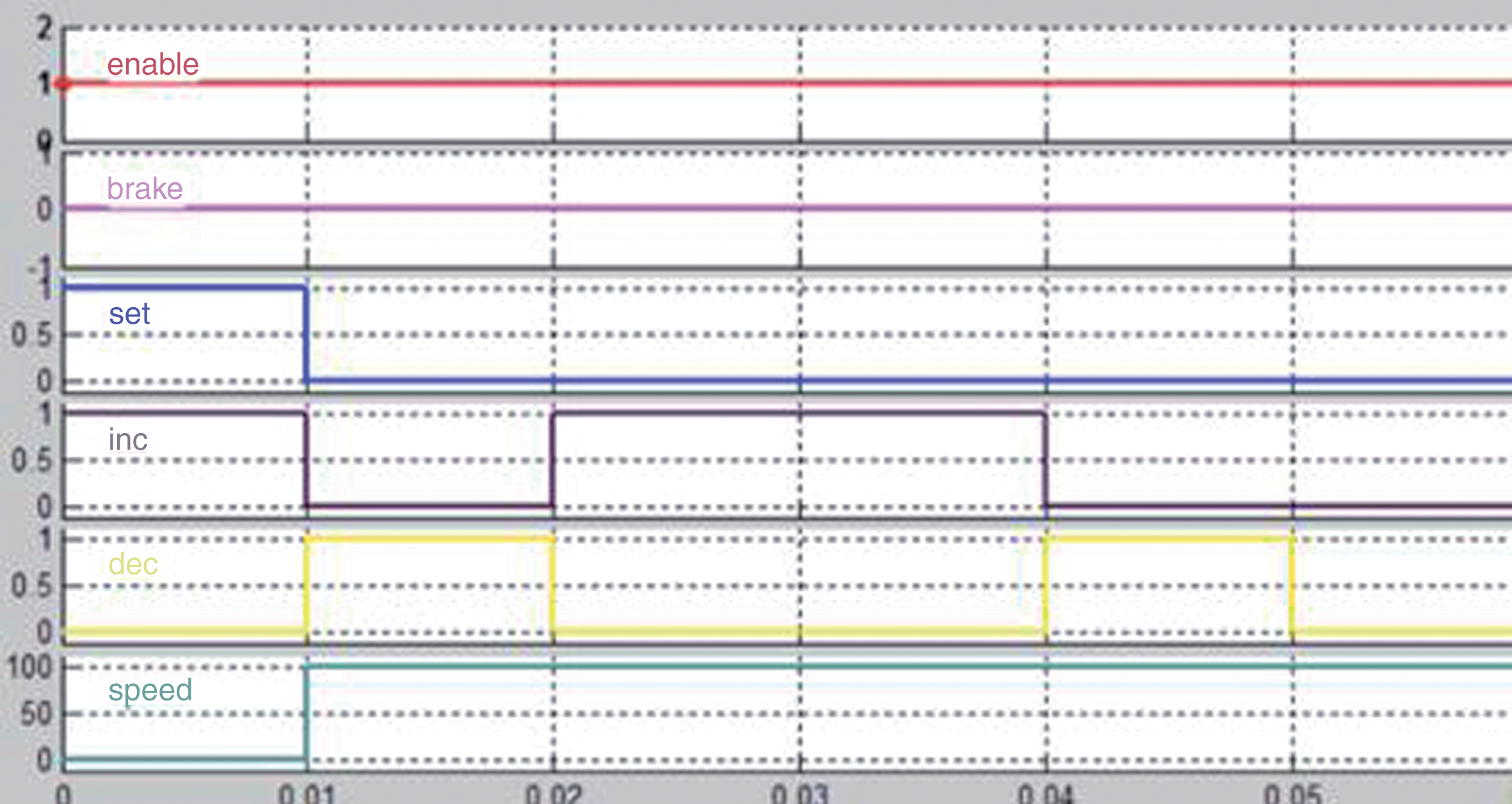
Test signal obtained during CCS simulation.
The test signals thus obtained for enable, break, set, increase, decrease and speed are shown in the Fig. 14. Now in order to obtain the test paths we will be using an online graph coverage application tool by Paul Ammann [19]. Before using this tool, we need to convert the state-chart machine into a more simplified automata- Finite state machine in which we have obtained four logically distinct states as 1,2,3 and 4. The coverage criteria used for generating test paths is Edge-Pair Coverage in Table 1.
6 test paths for Edge-Pair Coverage
Table 2 depicts the test paths generated by traversing all the test requirements with side-trips. The Table 3 describes the least possible test paths which are generated when Edge-Pair Coverage Criteria is applied using the Prefix-Graph Algorithm.
Indirect routes traversed by the coverage criteria
2 test paths needed for Edge-Pair Coverage using the Prefix Graph Algorithm
The FSM shown below in Fig. 16 represents state off as 1, On as 4, Set as 2 and Idle as 3. The edge pair coverage is a criterion in which pair of edges are applied for traversal of the graph.
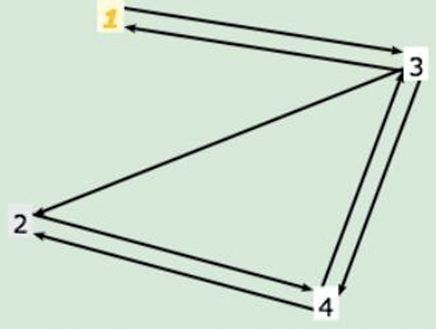
Simplified finite state machine.
13 requirements are needed for Edge-Pairs [1,3,1], [1,3,2], [1,3,4], [3,1,3], [3,2,4], [2,4,2] [2,4,3], [4,2,4], [3,4,2], [3,4,3], [4,3,1], [4,3,2], [4,3,4].
The test paths thus obtained using this methodology provides effective means to completely traverse all the states of a system. Using Graph coverage criteria, there is less redundancy of test paths and the nodes are visited directly.
The automated generation of test paths and test signals thus obtained provide minimal traversal of all the requirements. The cruise control case study considered in this paper is just an example to show how well we can model any system using LabVIEW and produce more refinement in the design later using state-charts. Although the existing literature studied considers only the UML state-charts and FSMs directly for modelling the requirements. But if the requirements and specifications are modelled keeping double V-model into consideration and using tool such as LabVIEW, more sophisticated results can be obtained.