
Abstract
Traditional MESH-based high-voltage transmission line condition data acquisition and communication systems collect all types of transmission line related condition data using the wireless monitoring device, and transmit condition data to the information center point through the wireless mesh node by wireless multi-hopping. The traditional methods are easy to generate lagging response and the high energy consumption, which result in high system condition data loss rate and low comprehensive utilization value. Therefore, smart distribution network transmission line condition data acquisition and communication system is designed based on the overall structure of the system, including data acquisition module, data communication module, transmission line condition monitoring communication module, and wireless transmission module of transmission line condition data. Tension, ambient temperature, solar radiation temperature, and wind direction signals collected by the data acquisition module are transmitted to the data communication module. After the collected signals are packaged to wake up G24, and establish a good GPRS network connection for data transmission. The transmission line condition monitoring communication module adopts an embedded operating system, which can combine its own functions to cut down the operating system, to speed up the response to the interruption event. The MCU in the transmission line condition data acquisition and communication system of smart distribution network realizes the command control of G24 by sending AT commands through the UART port. Data exchange between terminal and master station and addition of data items ensure the normal and smooth data communication. The experimental results show that the designed system can significantly reduce the loss rate of transmission line condition data and improve the system’s comprehensive utilization capability.
Keywords
Introduction
In the global “green industry revolution” environment, with the deepening of the low-carbon life and low-carbon economy ideology, developed countries, under the leadership of the government, have proposed a series of strategic plans for electricity development. One of the most representative example is the “smart grid” concept, and smart distribution network is an important part of smart grid. At present, the operation, maintenance, and management of power transmission equipment still face many challenges: (1) The large-scale power grid structure of ultra-high voltage, large-capacity, long-distance, the West-to-East transmission, and the North-to-South transmission add the pressure on operational maintenance and control capabilities of power transmission equipment. (2) The micro-topography and micro-meteorological characteristics of the West-to-East transmission channel are obvious, and extreme weather such as ice, snow and strong thunderstorms tend to be more frequent [1]. The operation risk of equipment stresses out the importance of network node planning algorithm based on the figure. More state-of-the-art data acquisition and communication systems for transmission lines of smart distribution network needs to be proposed to improve the management and control of transmission lines of large power network.
Condition data acquisition and communication requires real-time and reliable data. How to establish a high-speed and reliable communication method and ensure the real-time and accurate return of line condition monitoring data are issues that need to be considered in the construction of data acquisition and communication systems. The traditional data acquisition and communication system for high-voltage transmission lines based on MESH captures the condition data of each type of transmission line according to the wireless monitoring device. The wireless Mesh node transmits the condition data to the information center point via wireless multi-hopping [2], which is easy to result in loss of condition data during transmission and excessive power consumption. To solve these problems, a smart distribution network transmission line condition data acquisition and communication system is designed to reduce loss rate of transmission line condition data and power consumption of the condition data collector.
Material and methods
A GPRS module (Motorola G24) is controlled by a SoC microcontroller (C8051F040) to enable GPRS network access to the Internet, transmit wire tension and meteorological data of overhead transmission lines collected by the terminal to the monitoring platform, and complete communication with master station [3]. Short message service (SMS) is used as a communication aid to ensure the real-time and reliable data communication.
Overall structure of system
Overall structure of system is shown in Fig. 1. The acquisition terminal is installed on the overhead line tension tower. Within the set collection interval, MCU is utilized to control the collection of tension and weather data, and GPRS module to access the Internet through GPRS network, so as to complete data communication with the master station.
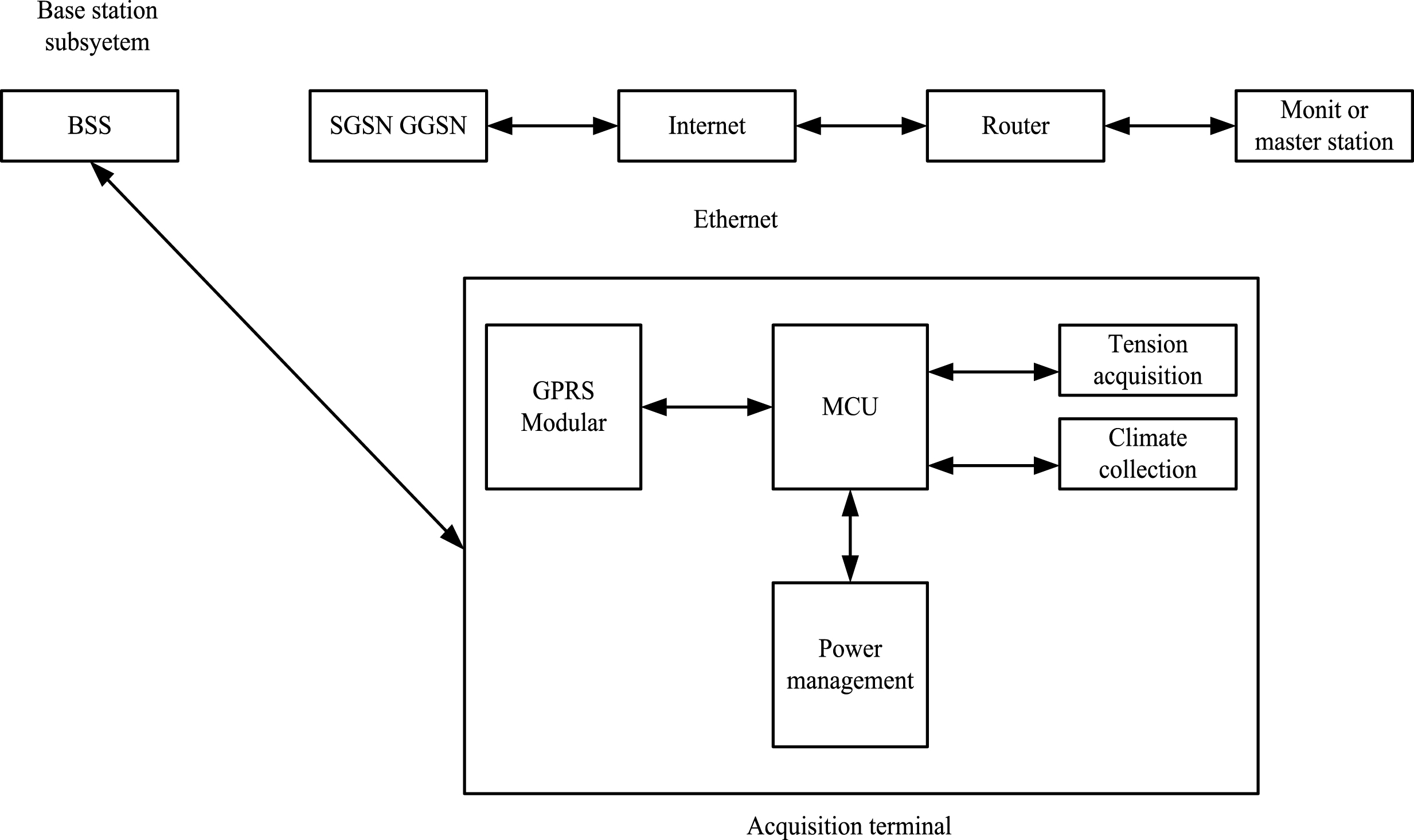
Overall structure of the system.
When data communication starts, data is wirelessly sent to GSM base station BSS via GPRS module, and GPRS data packet is sent from the base station to service support node SGSN, which communicates with the gateway support node GGSN. GGSN processes the data packet accordingly, and then sends to the monitoring master station connected to the Internet [4]. The data packet sent by the master station over the Internet first arrives at GGSN with locked address, and then GGSN forwards it to SGSN attached to mobile station to reach GPRS module. Multiple collection terminals can establish multiple TCP/IP connections through the GPRS network and designated port of the monitoring master station, so as to achieve the purpose of multi-point real-time monitoring. The entire system also includes SMS communication mode to ensure smooth real-time communication. Based on the overall structure of the system, other parts of the system are effectively designed.
Design of data acquisition module
The hardware design block diagram of entire terminal is shown in Fig. 2. Tension sensors are used to measure tension of overhead lines. A preamplifier circuit is placed close to the output side of the tension sensor considering the serious electromagnetic interference near the actual transmission line. TMP36 from Analog Devices is used as a temperature sensor to measure the ambient temperature and the radiation temperature of the solar wire and output the voltage signal [5]. The chip has the characteristics of high temperature accuracy, good linearity, and low power consumption. The wind speed and direction sensors are used to measure the wind speed and direction on the overhead lines, and convert wind direction into the voltage signal, and convert the wind speed into unipolar PWM waves of different frequencies. All signal lines outputted by sensors are protected by double-shielded wires, filtering and isolation, so as to minimize interference.

Terminal hardware design block diagram.
The C8051F040 from Silabs, a fully integrated mixed-signal system-on-chip with a high-speed CIP-51 core and rich analog and digital resources, is used as a MCU. The power management system consists of a solar photovoltaic array, a lithium-ion battery, and related control units, which can meet the needs of power supply for years [6]. In order to meet the needs of storing data, the system has expanded SPI interface Flash of 4Mbit.
After the acquisition interval is reached, the MCU controls the power of the front sensor. Tension, ambient temperature, solar radiation temperature, and wind direction signals are strobed by the analog switches in the conditioning circuit in turn, and the corresponding data is obtained by the 12-bit A/D converter integrated in the MCU. The wind speed signal is passed through the MCU’s external signal input port Tn and counted within 1 s.
G24 from Motorola is utilized as the GPRS module of the acquisition terminal. The G24 is a high-speed GSM/GPRS/EDGE module with built-in TCP/IP protocol stack [7]. The operating temperature range is –20 to 60°C and the operating voltage is 3.3 to 4.2 V. The G24 is mainly composed of a baseband processing module and a GSM radio module. The baseband processing module consists of a MCU, a DSP, a power management module, memory modules (Flash and SRAM), and application interfaces. The GSM radio module consists of an RF transceiver, an RF power amplifier, and an RF front-end antenna.
The main connection circuit of G24 is shown in Fig. 3. G24 requires an external SIM card to work. The control of G24 communication is realized by sending AT commands to its UART port. ON_N controls the switch of G24, and RI_N signal indicates that G24 receives a voice call, and WKUPI_N controls G24 to enter or exit the sleep mode [8]. G24 is kept connecting with the network during hibernation and monitors the network. The sleep interval of G24 at data communication is very important for saving energy of system.

G24 main connection circuit.
After the MCU packages the collected data, G24 is waked up, and GPRS network connection established byG24 is utilized for data transmission. At the same time, the monitoring master station can perform control script modification on the terminal through the Internet.
According to the “Technical Guidelines for Condition Monitoring System of Power Transmission Equipment” and “Technical Specifications for Transmission Line Condition Monitoring Agents” promulgated by the State Grid Corporation of China [9], the overall block diagram of the transmission line condition monitoring communication system is shown in Fig. 4.
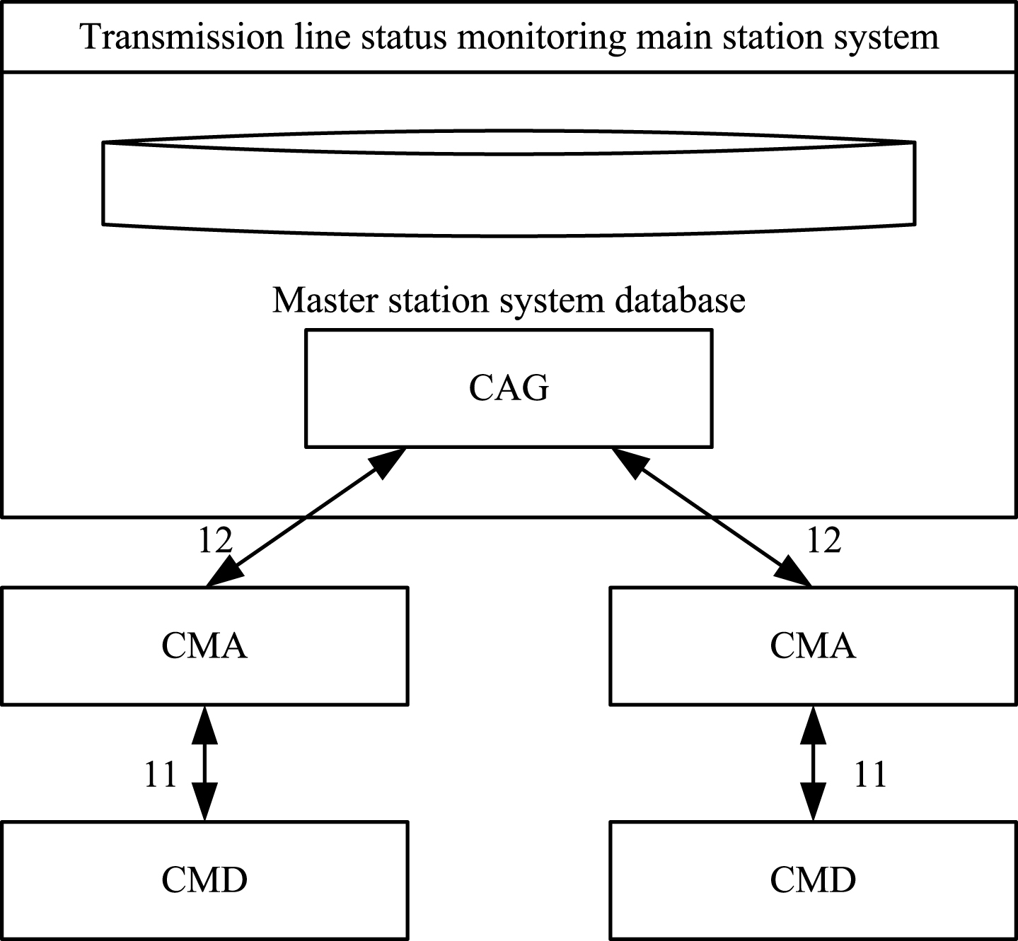
Transmission line condition monitoring communication structure chart.
As shown in Fig. 4, there are three important components in the system: the master station (including CAG), CMA, and CMD. The master station system (MSS) is a computer system that can access condition monitoring information of various types of power transmission and transformation equipment, and performs centralized storage and unified processing. The master station system includes a centralized database, CAG, data processing, data services, and various condition monitoring application modules. Condition acquisition gateway (CAG) is connected to a gateway device and deployed nearby the master station system, and is remotely connected to the Condition monitoring agent (CMA) [10]. A variety of condition information can be obtained from the CMA and verified using CAG. In the transmission line condition monitoring system, CAG is used. The CMA has the function of coordinating various transmission line condition monitoring devices in a local area and collects the data acquired by the condition monitoring device, which can replace the condition monitoring device to communicate with the master station system. The CMD includes a power transmission CMD and a power transformation CMD. The power transmission CMD is installed near or on the tower of power transmission equipment. The power transmission CMD collects the condition data of equipment being monitored, processes and saves [11]; on the other hand, it carries out data exchange with the CMA and the comprehensive monitoring unit. In addition, it directly connects with sensors to collect and process data. At the same time, the power transmission CMD can control the data acquisition unit by commands.
Figure 5 shows the structure of the data acquisition system, in which the CPU is an ARM Cortex M3 processor, and external SRAM is utilized to provide data space for the operating system [12]. The N and Flash stores data files for the system. The system has 5 RS232 communication ports for main channel, auxiliary channel, local communication, SDI interface and RS485 communication.
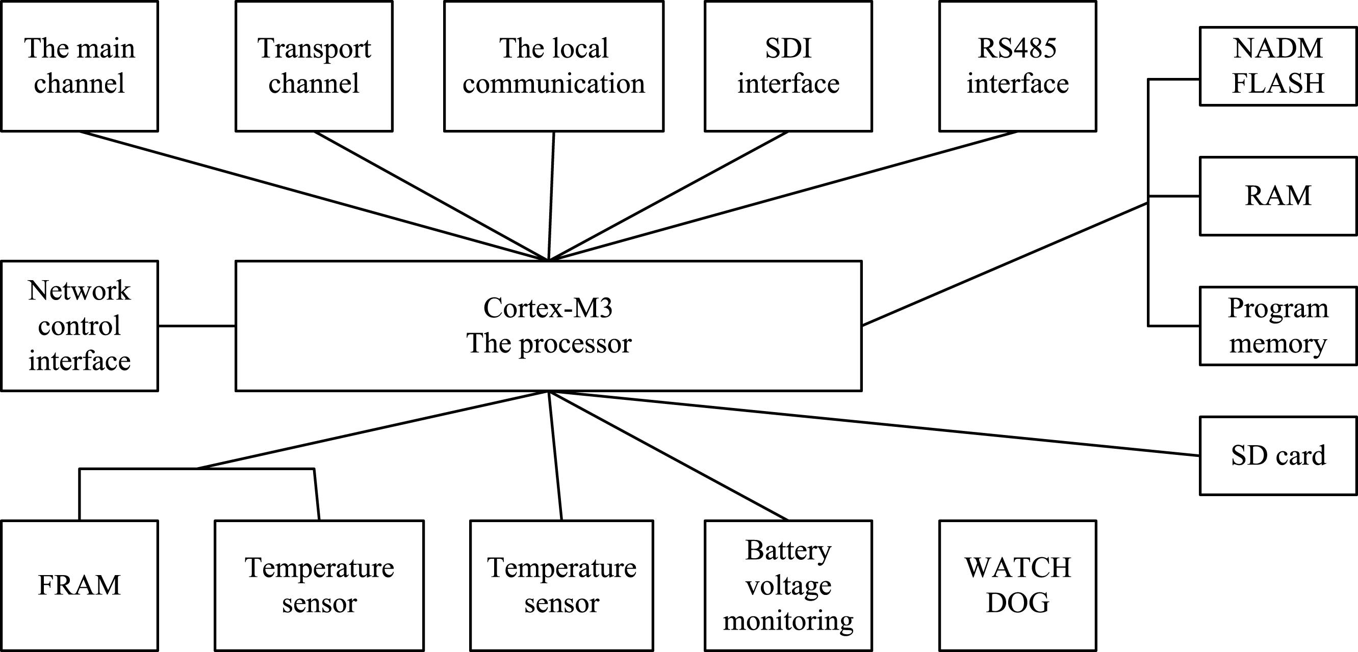
Data acquisition system structure chart.
The system uses the ARM Cortex-M3 processor, which includes all 16-bit Thumb instruction sets and the basic 32-bit Thumb-2 instruction set architecture. It has the advantages of low power consumption, low cost, and high performance. The performance is 2 times than that of ARM7 and the power consumption is 1/3 lower than that of ARM7. Its main features are:
The internal core of the 3-stage pipeline based on the Harvard architecture is adopted, and many powerful features such as single-cycle multiplication, branch prediction, and hardware division are integrated. The operating speed reaches 1.25DMIPS/ MHz while the power consumption is only 0.19 mW/MHz.
Adopting of Thumb-2 instruction set has stronger performance and higher instruction efficiency [13]. The Thumb-2 instruction set combines the code density of 16-bit instruction with the performance of 32-bit instruction, and its low-level key features make the execution of C code more natural, eliminating the need to use both ARM code and Thumb code alternatively.
Cortex-M3 has rich interruption priority. The preemption, tail chain, and late-arriving technologies make the response to interruption events faster [14], and the wake-up time at the low-power mode is only 6 CPU cycles.
The control of the G24 wireless communication module is achieved by sending the AT command through the serial port (UART) of the ARM processor.
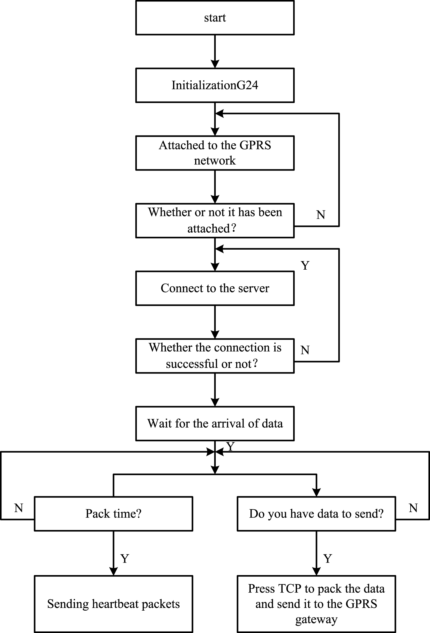
AT stands for Attention, AT instruction set is sent to a terminal adapter (TA) or a data circuit terminal equipment (DCE) from a terminal equipment (TE) or a data terminal equipment (DTE). Through TA, TE sends an AT command to control the function of the mobile station (MS) and interact with the GSM network service. The user can control the call, text message, data service, fax, etc. through the AT command [15]. Each command starts with the letter AT, which is followed by letters and numbers to indicate the specific function. Each execution of instruction has a corresponding return. For some other unexpected information (such as dialing from someone, no signal on the line, etc.), the module have corresponding information prompts, and the receiving end can conduct the corresponding processing. After powering the G24, the AT command is utilized to initialize G24. The communication flow of GPRS is shown in Fig. 6.
GPRS module logon connection sends data flow chart.
Related at commands
The control of MCU is complete by sending AT commands via the UART port. The AT command is a combination of strings represented by the ASDII code and has the following forms: command start string (“AT” prefix), command contents and parameters, and command end string (<CR>). There should be a certain interval between two AT commands. For some time-consuming AT commands, there must be enough time extension to guarantee the return information of G24.
After establishing a TCP/IP connection with the master station via a GPRS network, G24 can transmit data in two modes: AT command mode and Online Data mode. In the AT command mode, G24 returns the MCU corresponding command return information for each data transmission, and the transmitted data must be encoded in ASCII. In the Online Data mode, the user is allowed to directly transfer raw data between the G24 and the network via a socket established by the TCP or UDP protocol [16]. The G24 does not respond to the data sent by the MCU but directly sends it to the specified network location. The Online Data mode is utilized for data transmission in the proposed system.
When communication starts, the MCU confirms that the G24 communication is normal by sending an AT command. Then MMCU sends +CREG = 1 to register G24 to the mobile network, The + CGATT? instruction queries whether the G24 is attached to the GPRS network and then activates the PDP context. The GPRS network processes the APN information in the application. After the server performs user authentication and other processes, the G24 obtains a legal IP address. Under normal circumstances, the G24 will automatically attach to the GPRS network after power-on. With +MIPCALL = 1, the “CM-NET” command establishes a PPP connection between the G24 and the GGSN and assigns a dynamic IP address to the G24. And +MIPODM = 11024, “202,**.**.10”, 0 commands establish a socket connection with the remote end of the network based on the TCP protocol and automatically enter the Oline Date mode. Thereafter, the acquisition terminal can perform real-time data communication with the monitoring master station on the Internet [17]. After the data communication is over, the terminal MCU sends “+++” to G24 to make G24 exit the Oline Date mode and enter the AT command mode. Then, the terminal MCU uses +MIPCLOSE = 1 to close the Socket, and turns it on again when the next data communication starts.
Considering that the mobile network signal can be relatively poor under certain circumstances, the acquisition terminal cannot establish a TCP/IP connection with the monitoring master station [18], and the system has additionally designed the SMS mode. The command +CMGF = 1 is used to set the information format to text format, and then +CMGS = “136******”, <CR>Text(text content)<Ctrl_Z>is utilized to send data, and the data content is written with ASCII code.
Realization of gprs access to internet
Considering that under the on-site conditions, GPRS may be connected unstable and dropped, thus, relevant processing is added in the program to ensure the real-time data communication. After each AT command is executed, it must be processed according to the information returned by the G24. During a data communication, if there are 3 failures of creating Sockets [19], and this data will be sent using the SMS method. Before each data communication, the network connection failure flag needs to be queried to determine whether it is necessary to establish a PPP connection with the GGSN to obtain the dynamic IP. If the return operation of +MIPCALL command is not allowed or the MCU receives the error of +MIPSTAT (indicating that the G24 protocol stack is corrupted), G24 needs to be restarted.
Data exchange between the terminal and the master station
In order to ensure the normal and smooth progress of data communication, a request-response communication protocol is used between the acquisition terminal and the monitoring master station. The master station sends a command request to control the terminal to respond accordingly. Considering the characteristics of data communication in this system, the protocol data frame format shown in Table 1 is formulated.
Protocol data frame format
Protocol data frame format
In the communication process, the master station sends the following types of request data frames as required: request Server interface. The function of this is to return its interface pointer by giving the name of the OPC server.
IOPCServer* Instantiate Server (wchar_t ServerName)
{CLSD CLSID_OPCServer, HRESULT hr, LONGcmq = 1;
Hr = CLSID FROM String (ServerName; &CLSID_OPCServer;
MULTI_Qiqueue [1] = {{&ID_OPCServer, NULL, 0}};
Hr = C0Create Instance Ex((CLSID_OPCServer, NULL,CLSCTX_SERVER,
&CoServerInfo,cmq,queen);
Return(IOPCServer*queue [0], PItf,)}
Function IOPCItemMgt:: Add Items is used.
HRESULT hr:
OPC ITEM DEF Item Array [1] = {{L"", ITEM_D,FALSE,1,0,
NULL,VT,0 }};
OPC ITEM RESULT* pAdd Result = NULL;
HRESULT* pErrors = NULL;
Hr = p IOPC Item Mgt->Add Item s (1, Item Array, &pAdd Result,
&pErrors);
hServerItem = pAddResult [0]. hServer; //Add Itemto Group, and create OPCItem as object.
Item is a structure variable corresponding to the added data item [20], where ITEM_ID corresponds to the name of the OPC data item to be accessed. If OPC has established a connection with the PLC, then the data item name corresponds to the name of read/write PLC module. Taking the PLC connection established above as an example. If the connection mode is S7, and the connection name is S7 connection_1, and the module to be accessed is the PLC’s input IO port IB0, 1, then the ITEM_ID name is S7: [S7 connection_1]IB0, 1. Only correctly setting the data item name will enable the client to access the PLC correctly.
Results
The experiment is conduced to verify whether the transmission line condition data acquisition and communication system of smart distribution network designed in this paper is effective. The transmission capacity of the line of the distribution network in a certain area is simulated and analyzed. The experimental simulation scenario is set to be 2000 m×1000 m, and the smart distribution network has a linear distribution, the number of simulation nodes is 10, the distance between adjacent nodes is 200 m, the transmission radius of the nodes is 250 m, and the carrier monitoring range is 550 m. The routing protocol uses AODV and the packet transmission rate is 200 kbit/s. The system proposed in this paper is compared with the traditional MESH-based high-voltage transmission line condition data acquisition and communication system, and the Cortex-M3 processor-based transmission line condition data acquisition and communication system respectively in terms of throughput and lost packet of nodes. The comparison results are shown in Figs. 7 and 8 respectively.
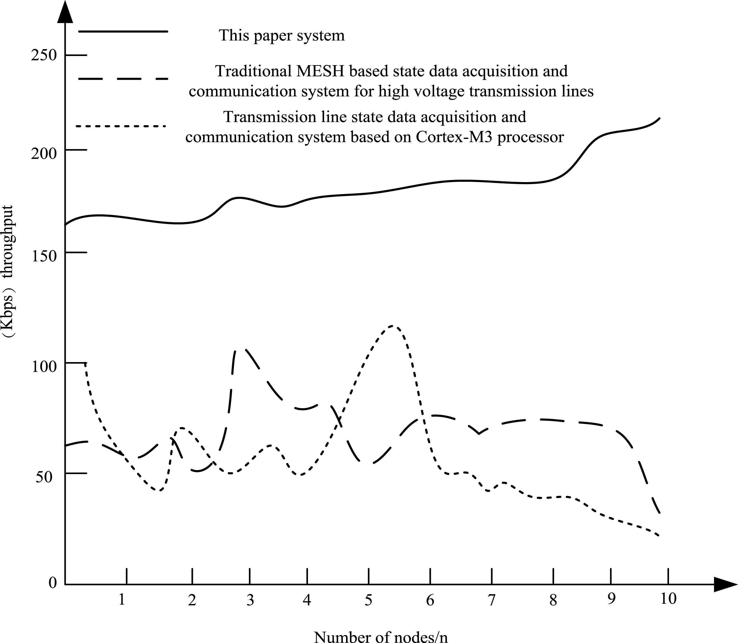
The relationship between the number of nodes and the throughput.
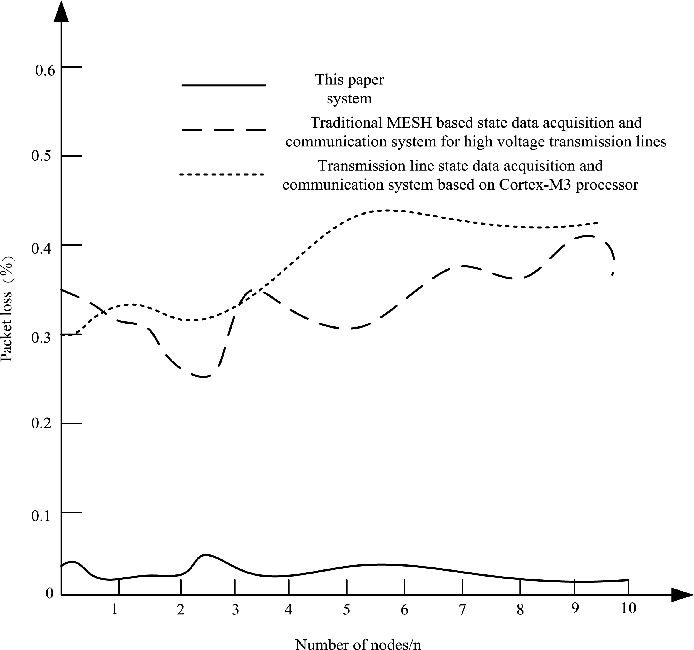
The relationship between the number of nodes and the rate of packet loss.
Figure 7 shows the throughput of condition data of the transmission line nodes in the same smart distribution network for the three systems. It can be seen that with the increase of the number of nodes, the amount of transmission line condition data of the proposed system is also increasing, because the proposed system processes these data concurrently. The throughput of data of the other two systems decreases with the increase of the number of nodes, and the processing capacity fluctuates greatly because the system transmits line condition data in the form of wireless relay and cannot process the line condition information obtained from smart distribution network transmission line concurrently. From the throughput of the system tonodes of the line condition, it can be seen that the application effect of the proposed system is stronger [21–28].
Figure 8 shows the loss curves of transmission line condition data of three types of system nodes. It can be seen that the loss rate of the transmission line condition data of smart distribution network obtained by the proposed system is lower and the packet loss rate of the condition data of different nodes is very low. It is almost 0, indicating that the quality of the condition data collected by the proposed system is high, and the information covered is wider. The data loss of other two systems at different nodes is more serious, and the loss of node information is about 40%. The completion of the transmission line information contained in the node is poor, and the data communication quality is poor.
The key of data acquisition of transmission line condition of smart distribution network is data collector. When analyzing the validity of the proposed system, verifying the power consumption of data collector and the time needed for data collection also analyze the effectiveness of the proposed system. The comparison of the condition data collection time of the 15 power transmission lines in the smart distribution network of a certain region and the power consumption in the data acquisition process of three systems are shown in Tables 2 and 3 respectively.
Three kinds of system state data acquisition time comparison results(s)
Power consumption results of three system acquisition state data(kw)
To facilitate the comparison of the time for collecting condition data of three systems, the time results in Table 2 are represented in the form of polylines, as shown in Fig. 9.
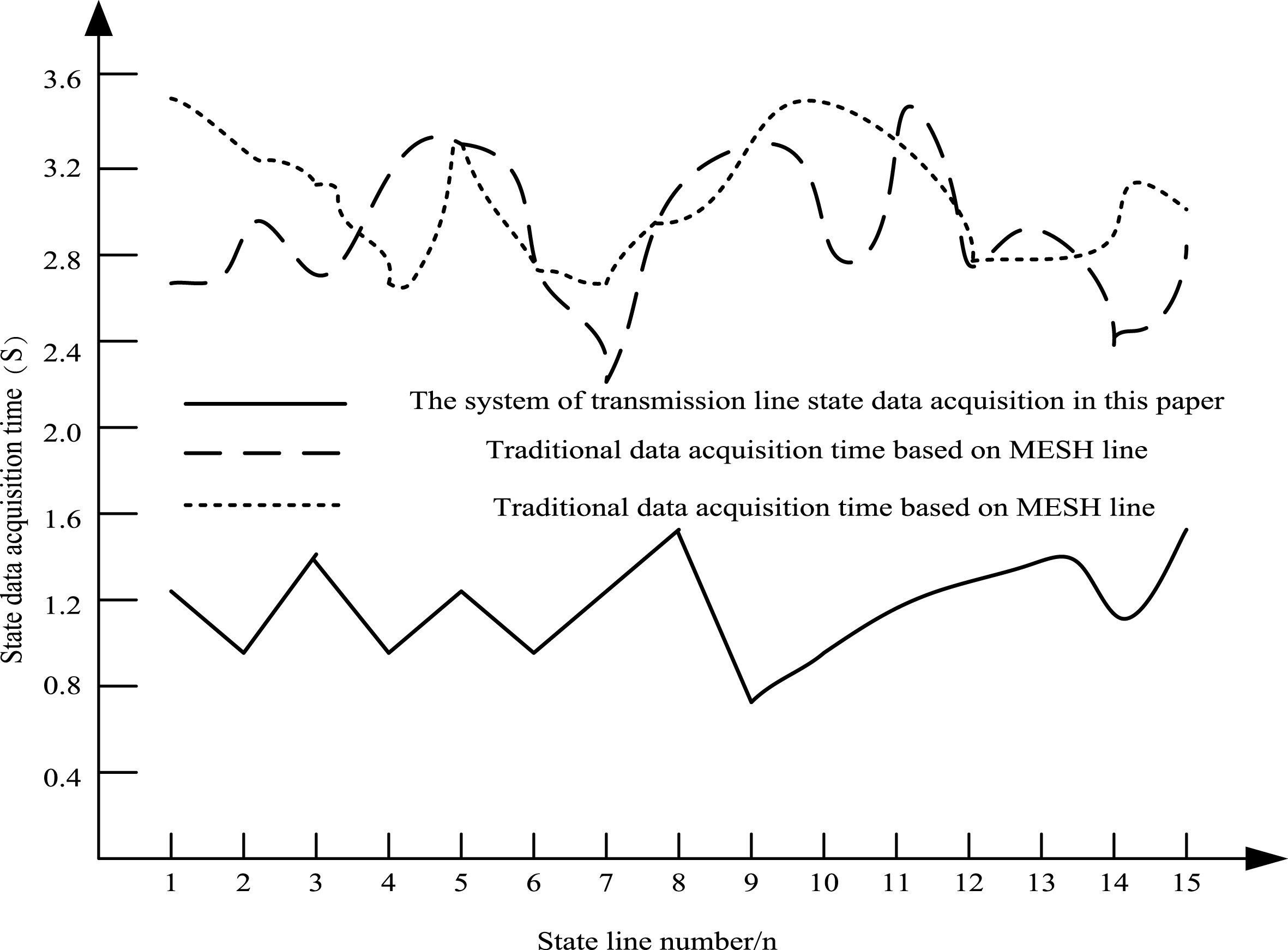
Three kinds of system state data acquisition time(S).
The data collection rate of the smart distribution network transmission line of the proposed system is the fastest compared to that of other systems. For different distribution network transmission lines, the proposed system can quickly and accurately obtain the condition data, and the data acquisition time is always less than 1.6 s, which is the curve with the lowest collection time in Fig. 9, and the other two curves show that the condition data collection time of the other two systems is much higher than that of the proposed system. This shows that the data collection of the proposed system has high collection efficiency.
The energy consumption of the system is verified by analyzing the power consumption of the collection of smart distribution network transmission line condition data of three system data collectors. The condition data collection of 15 transmission lines involved in the above experiment is also performed. The power consumption results of three systems are recorded and described in Table 3 and Fig. 10.
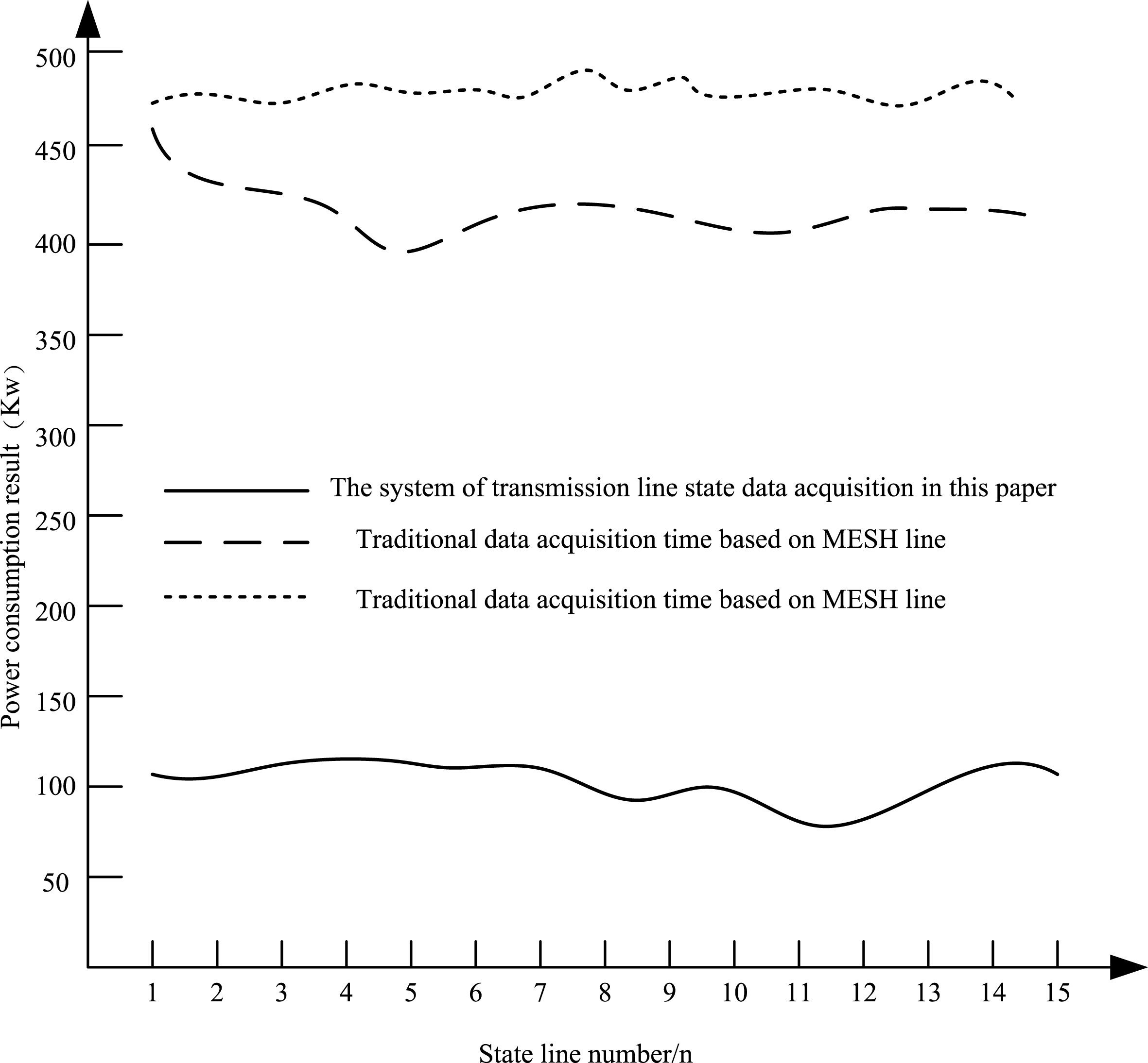
Power consumption results of three systems.
Analysis of the data in Table 3 shows that the power consumption of condition data of transmission line of smart distribution network collected by the proposed system is about 130 Kw. The power consumption of the traditional state-of-the-art MESH-based high-voltage transmission line condition data acquisition and communication system and the Cortex-M3 processor-based transmission line condition data acquisition and communication system is higher and exceeds the power consumption of the proposed system by more than three times, which shows that the energy consumption of the proposed system is low.
The expert evaluation method is used to evaluate the system proposed in the paper, the traditional state-of-the-art transmission line condition data acquisition and communication system based on MESH and the Cortex-M3 processor-based transmission line condition data acquisition and communication system. The evaluation is carried out on three parts, including time used for collecting the condition data of the transmission line, power consumption of the condition data and transmission effects of transmission lines. The evaluation results given by15 experts are selected as experimental reference data, and the evaluation results are described in Table 4.
Expert evaluation results
It can be seen from Table 4 that 15 experts have different evaluation results for the three systems. The scores of the proposed system are 95.7, 95.2 and 96.2 for the three evaluation parts, time used for collecting the condition data of the transmission line, power consumption of the condition data and transmission effects of transmission lines. And the overall evaluation score is excellent, and the comprehensive results of the proposed system are high. Experts give low scores on traditional MESH-based high-voltage transmission line condition data acquisition and communication system and Cortex-M3 processor-based transmission line condition data acquisition and communication system. For both of them, the score is lower than the passing score. The comprehensive evaluation results shows that he application of smart data transmission line condition data acquisition and communication system designed in this paper is better.
A smart distribution network transmission line condition data acquisition and communication system is designed and described in this paper. The system controls GPRS module (Motorola G24) through the SoC microcontroller (C8051F040), so that the GPRS network can access to the Internet, and tension and weather data of overhead transmission line collected by the terminal can be transmitted to the monitoring platform and complete the control communication with the monitoring master station, which improves the throughput of condition data of the transmission line of smart distribution network and reduces the data transmission loss rate and power consumption, and saves the system energy through the sleep interval of G24.
Footnotes
Acknowledgments
This work has been supported by the National Natural Science Foundation of China under Grant Nos. 61403069 and 61473066, Fundamental Research Funds for the Central Universities No. N162304003.