
Abstract
The Distributed Generation (DG) systems are highly useful in recent days for increasing the penetration of renewable energy, in which the design of grid connected inverters is one of the demanding and challenging task. For this reason, different controller strategies are developed in the traditional works for controlling the inverters with increased efficiency. But, it has the major limitations of increased computational complexity, steady state error and reduced compensation capability. To solve these issues, this research work aims to design a new controller by implementing a novel Monkey King Evolution Algorithm (MKEA) for grid connected converters. The motive of this work is to increase the overall effectiveness of the power system by controlling the inverter without affecting its output. Also, it aims to provide a secure and convenient controller for the power converters. Here, the information that is obtained from the system which includes real power, distorted power due to load, reactive power of load, and apparent power of inverter are taken as the input. Later, the four numbers of monkeys are initialized, which evaluates the best solution based on these parameters. Sequentially, the monkey king obtains the best solutions from the monkeys, using which the most suitable and best solution for taking the decision is selected. Based on this, the reference current is generated by performing the voltage regulation, and abc to dq0 transformation processes. During simulation, the efficiency of the controller is analyzed by using the measures of phase voltage, phase current, active power, reactive power, apparent power, grid voltage, and output voltage. The Total Harmonic Distortion (THD) is effectively reduced by using the MKEA based controller design. Extensive simulation and experimental results are presented to validate the effectiveness of the proposed controller and control strategy.
Keywords
Introduction
The Grid connected inverters [1, 2] play an essential role in Distributed Generation System (DGS) and micro-grids. It offers an interface for both Distributed Energy Resources (DERs) and Renewable Energy Resources (RERs), in which the DER is determined as the small scale power generation source that improves the performance of the electric power grid by providing alternatives. Typically, the multi-function grid connected converters are highly advantageous because it is mainly used to enhance the power quality of the system. Moreover, it is widely used in the Photovoltaic (PV) inverters for generating a regulated AC current [3, 4]. Furthermore, the multilevel inverters are widely used due to its advantages of minimized electromagnetic interference, core loss, filter size, and noise level. So, it is largely utilized in the applications of energy based grid connected systems, which includes both wind generation system and PV generation system [5–8]. In a general grid connected PV system, a single or series of modules generates a DC current based on the environmental conditions. The inverters that are connected with a PV converts and transfers the PV power to the grid in a reliable and efficient manner [9].
Problem identification
In most of the PV systems, the technical problems [10] such as harmonics distortion, electromagnetic interference and islanding detection are considered as the important issues. Due to the conduction loss and switching loss [11], the output power of the power supply is decreased. To solve these problems, different techniques are developed in the traditional works for improving the efficiency. But, it has the major problems of increased DC current injection at the grid and power loss. Also, it uses the multiple converter stages such as DC-DC and DC-AC, which reduces the overall efficiency of the system [12]. The efficiency of the inverter highly depends on the characteristics of the inverters, DC input voltage, and ratio of array peak power. These parameters should be considered for sizing the grid connected PV system [13, 14]. Based on the aforementioned problems, this research work motives to develop a new controlling strategy for a grid connected inverter [15].
Objectives
The key objectives of this work are as follows: To improve the overall efficiency of the power system, the Monkey King Evolution Algorithm (MKEA) is proposed. To analyze the best solution, the parameters such as real power, distorted power due to load, reactive power of load, and apparent power of inverter are considered. To generate the pulses for controller, the voltage regulation and abc to dq0 transformation processes are performed. To control the inverter without effecting its output voltage for providing a secure and convenient controller for power converters.
Organization
The rest of the sections in the paper are structured as follows: the existing techniques and strategies used for grid connected inverters are surveyed in Section II. A brief description about the proposed optimization based controlling strategy is provided with its clear flow in Section III. The simulation results of the proposed mechanism are analyzed and its superiority is proved by comparing it with the traditional approaches in Section IV. At last, the overall paper is summarized and the future work is stated in Section V.
Related works
In this section, the traditional controlling strategies are analyzed and discussed with its benefits and drawbacks.
Liu, et al. [16] implemented a three phase grid connected inverter for minimizing the DC-side voltage limit with low harmonic content. Here, the resonant frequency was determined for avoiding the resonance problem in the region of harmonic spectrum. Also, the characteristics of inverter that includes inductor and capacitor were considered during the design. Pan, et al. [17] implemented a mathematical model using three different control schemes for a grid connected inverter. The control mechanisms that were considered in this work are grid current control, inverter side inductor current control, and weighted average current control. Guo and Guerrero [18] introduced a feedback mechanism for designing a conventional integral controller. The motive of this paper was to enhance the traditional PI controller by integrating it with a simple feedback term. Here, a simple Synchronous Reference Frame (SRF) transformation was applied to adjust the frequency of the controller. The mechanisms implemented in this work were as follows: Three phase SRF control scheme Single phase SRF control scheme
In this work, it was stated that high bandwidth utilization leads to instability and increased control delay. The benefit observed from this work was, it efficiently reduced the computer burden by extending the single phase applications. Alemi, et al. [19] designed a resonance suppression mechanism for avoiding the power loss in a grid connected inverters. Here, the Proportional Resonant controllers were utilized to regulate the current at grid side. Also, the measures such as gain, bandwidth, and phase were determined in the damping control system. The filtering parameters that were considered in this design are inverter, inductor, capacitor, grid side inductor and series inductor. Furthermore, the band pass filtering technique was utilized to extract the current at grid side. However, the methodology failed to efficiently regulate the current harmonics during the filter design. Wu, et al. [20] suggested a Zero Cross Distortion (ZCD) mechanism for reducing the control signals of the low frequency inverter. Moreover, the amplitude and frequency of the grid and filter inductor were analyzed with respect to the optimal Leading Exchanging Phase Angle (LPEA). Also, an actual inductor value was estimated by using an online filter inductor estimation technique. The limitation of this work is that, it requires effectiveness of the suggested technique by using different performance measures.
Rodrigo, et al. [21] developed two state of the art inverters for analyzing the behavior of grid connected Photo Voltaic (PV) inverters. In this paper, the Sandia’s PV array model was utilized to analyze the thermal and electrical behavior of the PV modules. Moreover, the inverter operation was characterized by using the parameters of efficiency and power. Here, the direct relation between the AC output power and array maximum power was estimated for determining the normalized AC power. The methodological features of both inverter and PV modules were considered for the design of PV generator. However, this work failed to analyze the effects of high resolution irradiance data for DC/AC conversion. Wu, et al. [22] recommended a Division Summation (D-Σ) control scheme for a single phase bidirectional inverter. The motive of this mechanism was to track the grid current references for the GC and rectification applications. The magnetization and demagnetization processes were performed by the authors using the division mode based on the buck converter operational principle, and the total current variation was estimated during the summation operation. Here, the control laws were derived by tuning the loops gains.
Tong, et al. [23] analyzed the behavior of the inverter by developing a single phase full bridge inverter. Here, the output current of PV array was delivered by connecting the PV array and utility grid. The output current of the inverter was synchronized based on the utility voltage and correlation factor. The benefit observed from this paper was, the efficient transference of the PV energy to the utility grid. Kumar and Sivakumar [24] configured a quad two level inverter by using the Sine-triangle Pulse Width Modulation (SPWM) mechanism, which performs power balancing. The motive of this work was to reduce the zero sequence current that is present in the output. Here, the five-level inverter configuration was operated by verifying the laboratory prototype. Also, the rectifier units were protected by implementing three control mechanisms. During fault detection, the reliability of the system was improved by the use of four pole induction motor drive. The advantage of this work was the attainment of an increased number of voltage levels for the induction motor. However, the performance of the inverter may be improved by implementing an efficient mechanism.
Wu, et al. [25] implemented a Cascaded Multilevel Grid Connected Inverter (CM-GCI) for reducing the harmonics in the signal. The authors were able to estimate the synchronous information accurately by using the Hybrid Filter Enhanced Phase Locked Loop (HF-EPLL) technique. Also, the desired carrier frequency was calculated by ensuring the non-ideal grid conditions. Moreover, the efficiency of the scheme was improved by analyzing the grid disturbances with reduced loss and current. The switching loss was reduced by minimizing the carrier frequency with the use of efficiency enhancement scheme. From the paper, it was observed that the grid current required to be satisfying the particular standard limit under varying grid conditions. Ahmad and Singh [26] analyzed the different leakage current reduction methods for selecting the suitable mechanism to implement in the grid connected PV system. The measures that are considered to compare these techniques were semiconductor device loss, Total Harmonic Distortion (THD), efficiency and leakage current. Here, the common mode characteristics were validated by the use of modified Common Mode Voltage (CMV) clamping models. In this study, it was stated that the grid connected inverter has the key objectives of current control, grid synchronization and DC voltage control. Among them, the current controller was mainly used to regulate the current that is injected into the controller and grid. The major benefit of this paper is its guidelines to the researchers to choose the suitable transformer-less inverter topology.
Xu, et al. [27] introduced a parameter identification model for analyzing the operation of grid connected PV system. Here, the control parameters were identified by implementing the Simulated Annealing Particle Swarm Optimization (SAPSO) technique. The measures such as convergence speed and accuracy were considered for analyzing the superiority of the suggested technique. Also, the strong generalization ability of the inverter was evaluated by identifying the consistency between the results. However, the program running for the PV inverter was slow, and to identify the parameters several iterations are required. Merai, et al. [28] considered a Multi-Function Grid connected Converters (MFGcCS) for providing the solution to the power quality problems. Here, the power quality of MFGcCS was evaluated at various operating modes. Also, the stability of the power system was maintained by performing the reactive power compensation, micro-grid dynamic stability enhancement, active filtering, grid voltage and frequency supports. Javadi and Haddad [29] developed a Hybrid Series Active Filtering (HSeAF) technique for improving the quality of power in a single phase systems. In this paper, the current harmonic distortion was prevented by using the HSeAF technique. The major advantage of this technique is the efficient compensation of the non-linear harmonic voltage and current producing loads.
Zhonk and Hornic [30] aimed to improve the power quality of inverter by implementing a cascaded current voltage control mechanism. The implementation of a control scheme has enabled the seamless transfer of the operation mode. Also, it reduced the total harmonics distortion in both current and inverter local load voltage. Hassaine, et al. [31] provided an overview about the power inverter topologies based on the measures of efficiency, control power, and harmonics distortion. Moreover, the advantages and disadvantages of various controlling strategies were discussed in this paper. Zou, et al. [32] developed an optimization based delay time control method for the grid connected inverters. Here, the single loop inverters were used to filter the elements by ignoring the equivalent series resistance. Moreover, the system stability was maintained by reducing the time delay.
In this survey, the benefits and demerits of the traditional works are investigated. The major drawbacks that are analyzed and observed from the traditional works are as follows: It is incapable to track the sinusoidal reference without steady state error. Deprived disturbance rejection capability. Increased complexity of the control for current generation. Failure to eliminate the steady state error. Reduced compensation capability.
To solve these issues, this research work aims to develop a new controlling strategy by implementing an efficient technique. Based on an extensive survey, the idea of utilizing an evolutionary algorithm for obtaining an effective controlling strategy upon the grid connected inverter has been greatly kindled. The so said strategy would be the first of its kind, and the design of controller to achieve a proficient operation of the inverter will be the ultimatum of this paper.
Proposed method
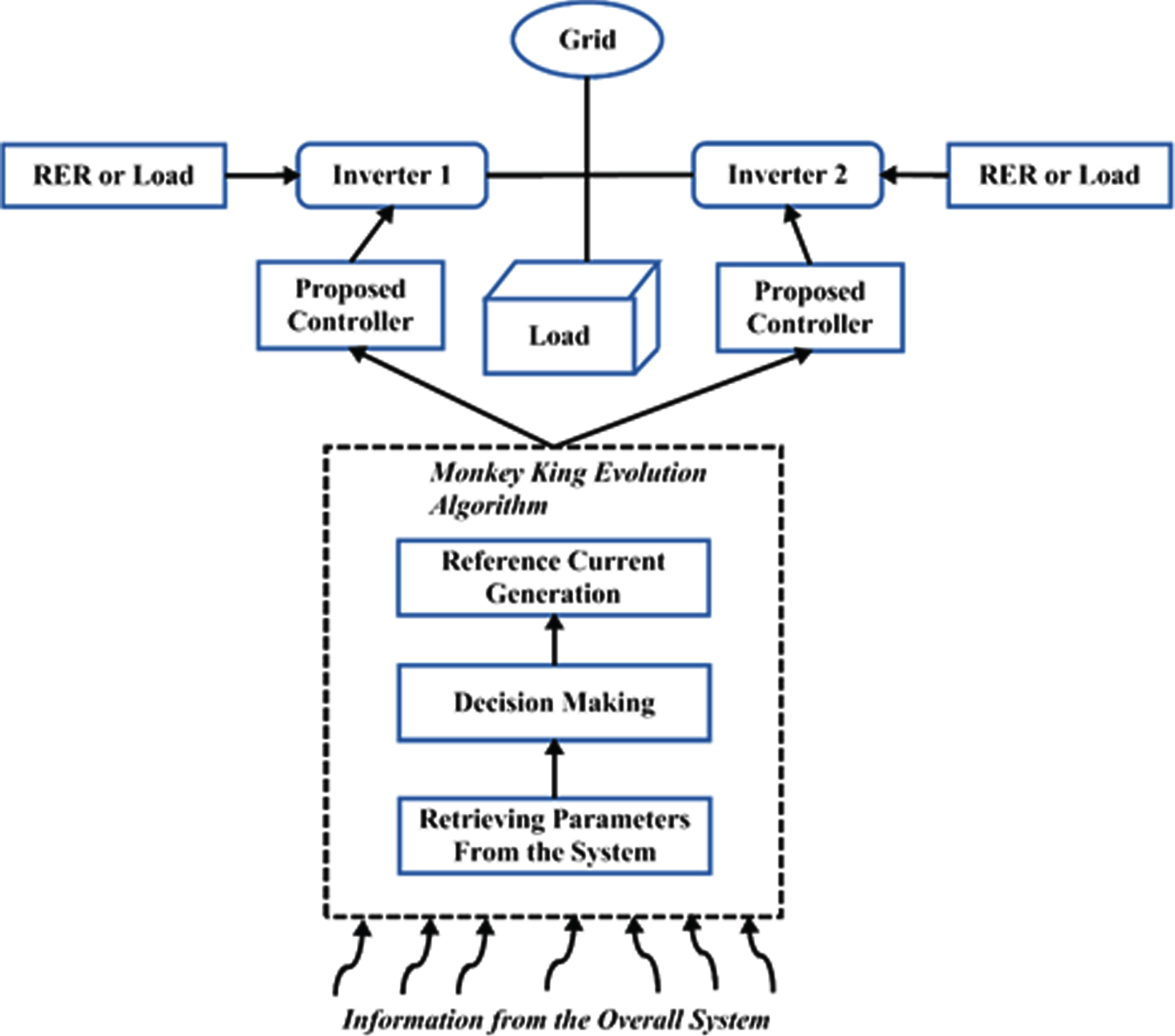
In this section, a clear description about the proposed methodology is presented. This paper aims to develop an optimization based controlling strategy for a grid connected inverter. For this purpose, the Monkey King Evolution Algorithm (MKEA) is developed for generating the reference current to the inverter. In this design, two inverters are connected with the grid and the optimized solution obtained from the MKEA is utilized by the controller for generating the reference current. The clear flow of the MKEA based controller design is shown in Fig. 1.
Flow of the proposed optimization based grid connected inverter.
The MKEA developed by Meng et al. [33], is an inspiration by the super power action of the monkey king, a famous character of a Chinese popular mythological novel, ‘Journey to the West’. Here, it is assumed that during a critical situation, the monkey king with super power transforms into several small monkeys. Then, the small monkeys search the solution for the appropriate problem, and report it to the monkey king for choosing the better solution. After receiving the feedbacks from all monkeys, the monkey king evaluates the best suitable solution, and then takes the corresponding action and moves forward with the small monkeys.
The flow of the MKES is depicted in Fig. 2. Here in this work, MKES is mainly developed for getting the optimal solution for reference current generation. In this algorithm, the number of monkeys (i.e. 4) and its position are initialized first. Then the information such as real power, distorted power due to load, reactive power of load and apparent power of inverter are collected from the system. After that, the monkey king receives the optimal solutions for these parameters from the monkeys, where the solution 1 is denoted as INS 1, solution 2 is denoted as INS 2, solution 3 is denoted as ω1, and solution 4 is denoted as ω2. Based on these values, the better decision is taken by the monkey king. The major benefits of using this algorithm are as follows: It is easy to implement It required only few parameters It has the ability to solve different kind of optimization problems Faster convergence rate Non-differentiability
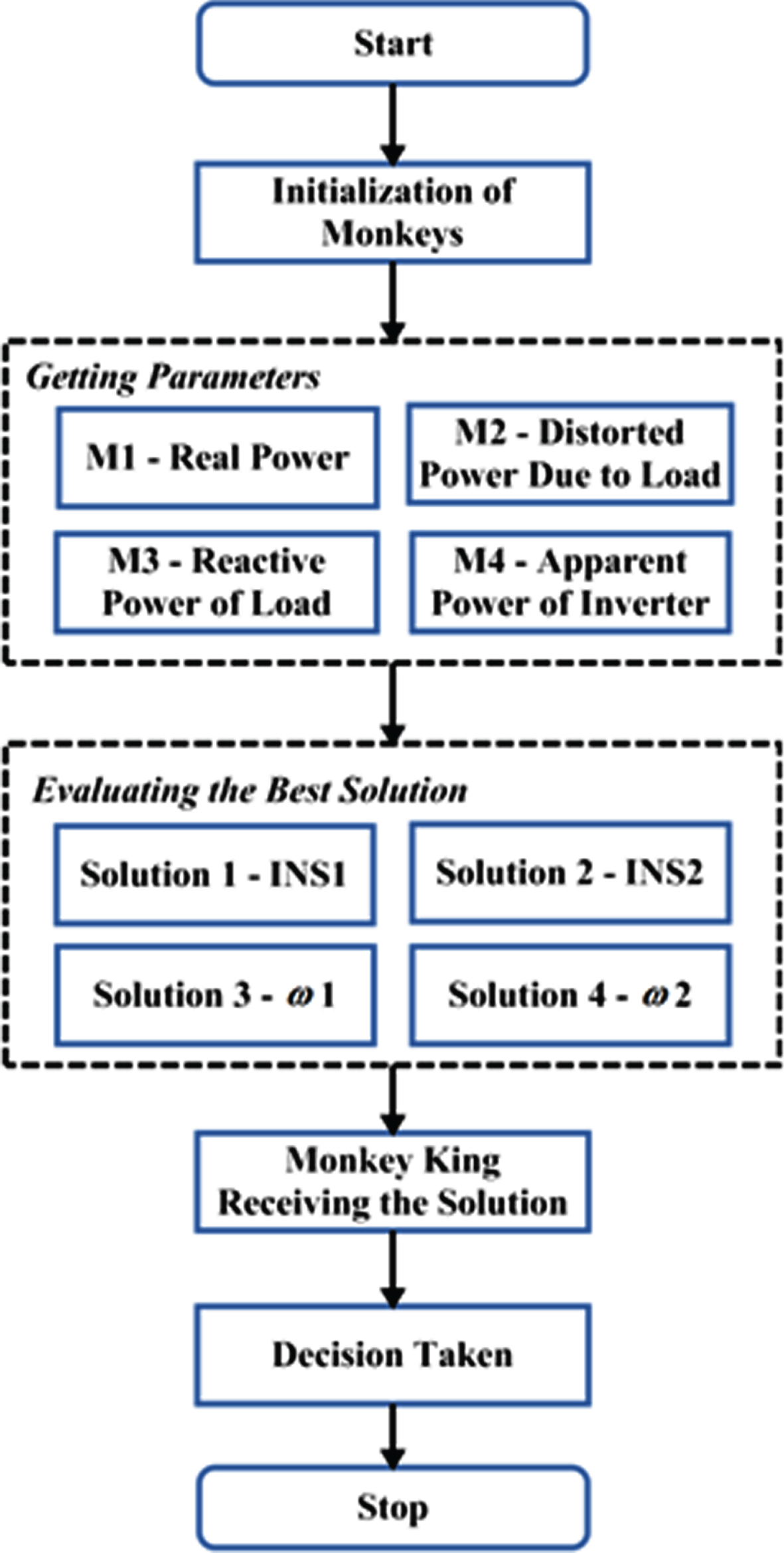
Monkey king evolution strategy.
After selecting the optimal solution, the reference current is generated as shown in Fig. 3 based on the values of INS 1, INS 2, ω1, and ω2 through which the inverter is ultimately controlled via proposed controller.
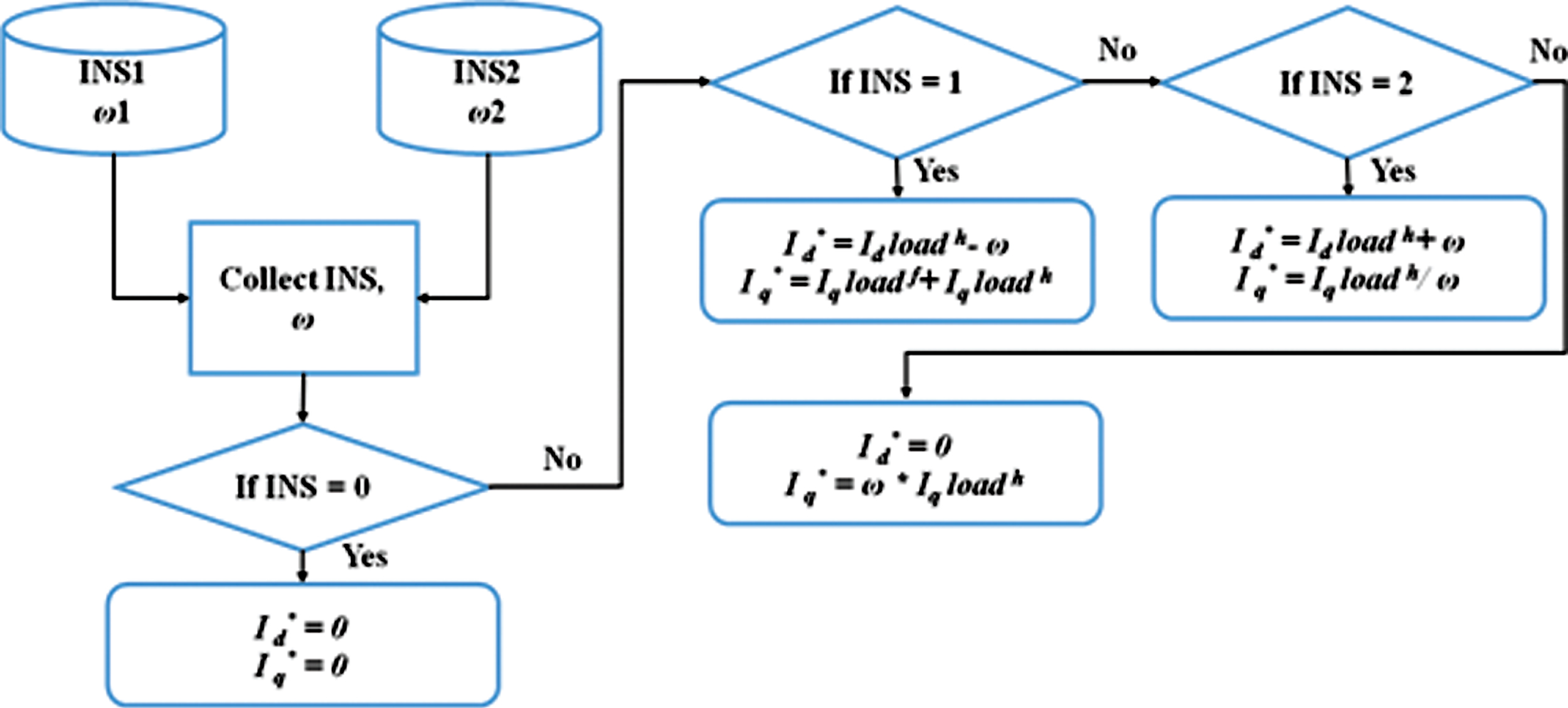
Reference current generation.
The parameters that are collected from the system are abbreviated in the algorithm as follows;
RP1: Real power of inverter 1,
RP2: Real power of inverter 2,
DP: Distorted power due to load,
AP1: Apparent power of inverter 1,
AP2: Apparent power of inverter 2,
RAP: Reactive power of load
Step 1: Initialize the number of monkeys 4;
Step 2: Getting the parameters of real power, distorted power due to load, reactive power of load, and apparent power of inverter;
Step 3: Then, collect the optimal information from all the monkeys;
Step 4: If
Controller design
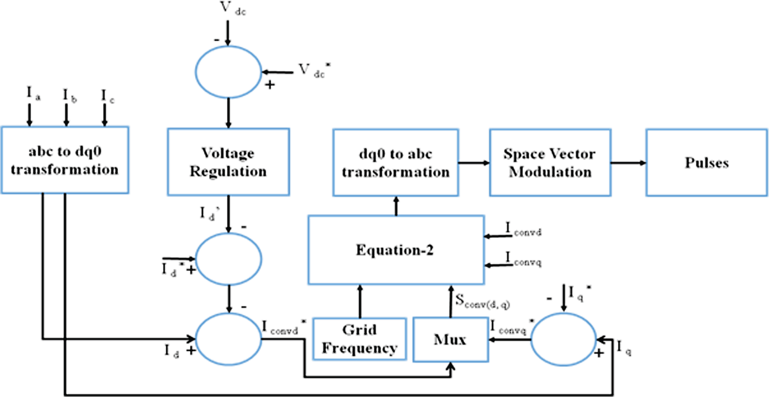
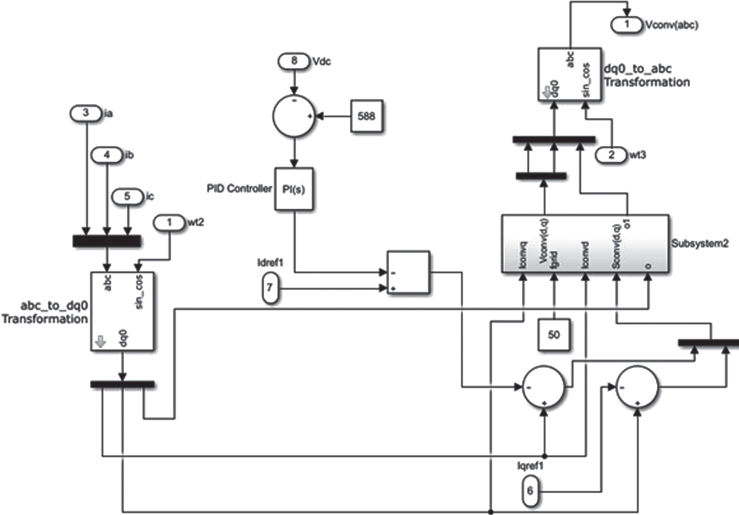
In this design, three phase current (i.e. Ia, Ib, and Ic) are given as the input for performing abc to dq0 transformation. During this process, the direct voltage and reference voltage are controlled by voltage regulation, and its output of direct current and indirect current are produced. Later, the value of ∂ is estimated based on the measures of converter current in q axis Iconvq, frequency of grid fgrid, and converter current in d axis Iconvd which is shown in Equation (1). The output which is obtained based on ∂ and Sconv (d,q) is shown in Equation (2).
Again, the dq0 to abc transformation is performed. Based on this operation, the pulses are generated by using the Space Vector Modulation. Figure 4 shows the schematic of proposed controller.
Proposed controller.
Here, the PI controller is mainly used to analyze the proportional and integral variations, where the output of the controller is manipulated as the variable input. Also, it regulates the voltage for maintaining the voltage at a constant level, which improves the dynamic response of the system by reducing the error rate. Moreover, the Space Vector Modulation (SVM) is employed to generate the pulses for inverter, which is a kind of interceptive model that uses rectangular pulses for modulation. Typically, the SVM is a control algorithm that synthesizes the reference signals based on the vectors. The three phase voltage source inverter should not be shorted and the output current must be continuous. Based on these conditions, the SVM generates pulses. In this technique, the pulse width modulation is in the high state, if the reference signal waveform is further than the modulated waveform. It is implemented based on the following processes: Sector selection Switching space reduction Carrier based modulation Switching carrier reduction
The major advantage of using SVM is that it effectively reduces the THD contents in the output voltage and current. The major advantages of the proposed controller are good dynamic response, increased robustness and reliability.
In this sector, the simulation results of the proposed MKES based controller design is analyzed by using different measures such as phase voltage, phase current, active power, reactive power, apparent power, grid voltage and output voltage. Using the above said measures and during the simulation, MATLAB/Simulink tool is used to test the effectiveness of the three phase grid connected inverter. The dynamic controllability of the system is tested with variation of load as shown in the Table 1.
Load variation
Load variation
The MATLAB/Simulink simulation of the system is shown in Fig. 5. The system consists of grid simulated with 50 Hz frequency with a line length of 100 km.
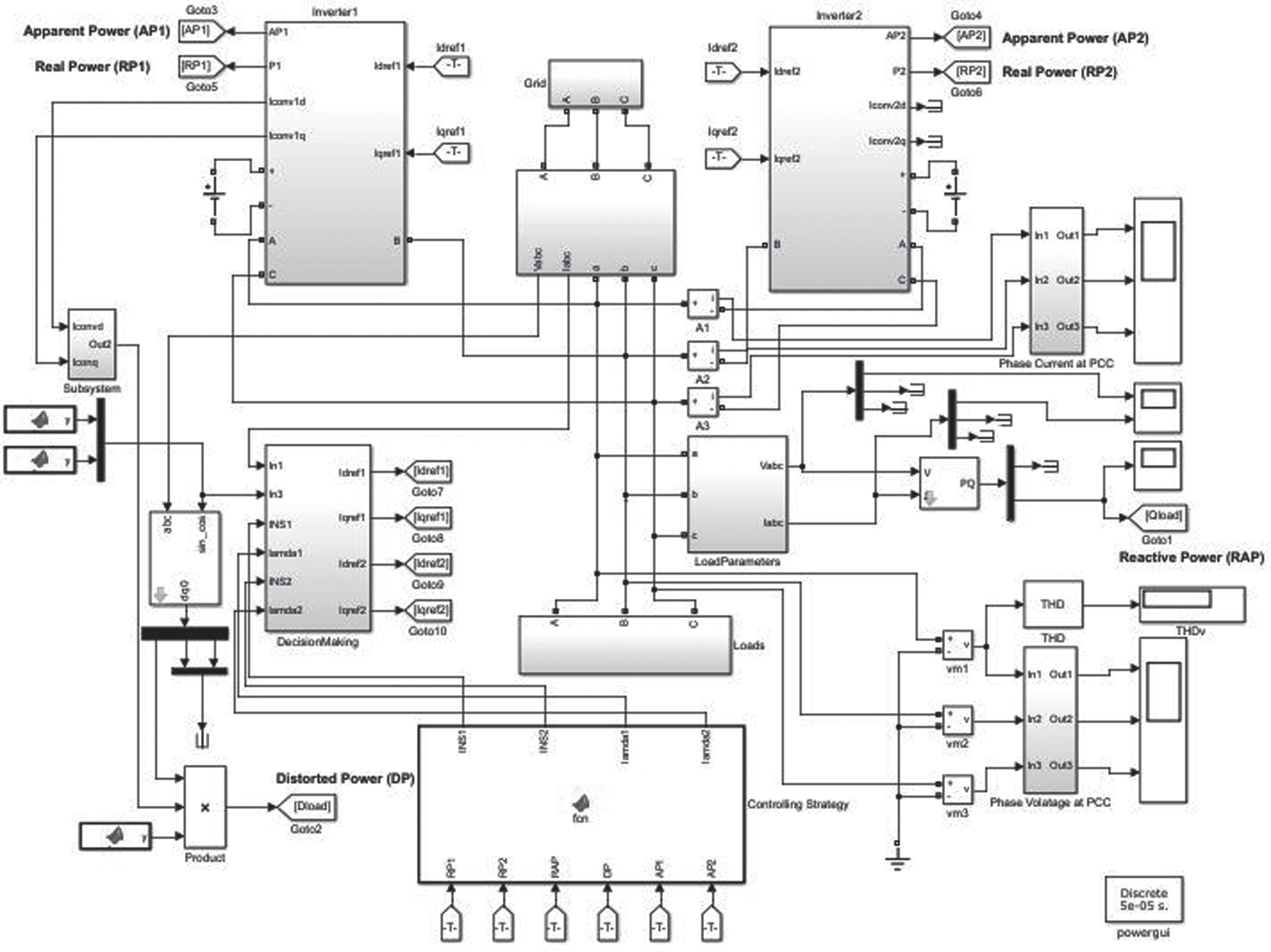
MATLAB/simulink model of the proposed system.
The loads that are connected to the grid are non-linear and reactive and are set with a timing control for variation as shown in Table 1.
The inverters are connected to the grid and the load at the Point of Common Coupling. The control strategy block receives the information of Reactive Power (RAP), Distorted Power (DP), Apparent Power of Inverter 1 (AP1), Apparent Power of Inverter 2 (AP2), Real Power of inverter 1 (RP1) and Real Power of Inverter 2. Based on this information, it provides solutions to the decision making block for deciding the optimal solutions for the reference current generation, and this is accomplished through novel Monkey King Evolution Algorithm. The decision making block then generates the reference current to the inverter through which the efficient operation of the inverter is achieved. Figure 6 shows the simulation of inverter which is connected to grid and load at the Point of Common Coupling with proposed controller. The controller output is given to the SVM for generation of pulses that needs to be given to the inverter switches. The simulation of the proposed controller is shown in Fig. 7.
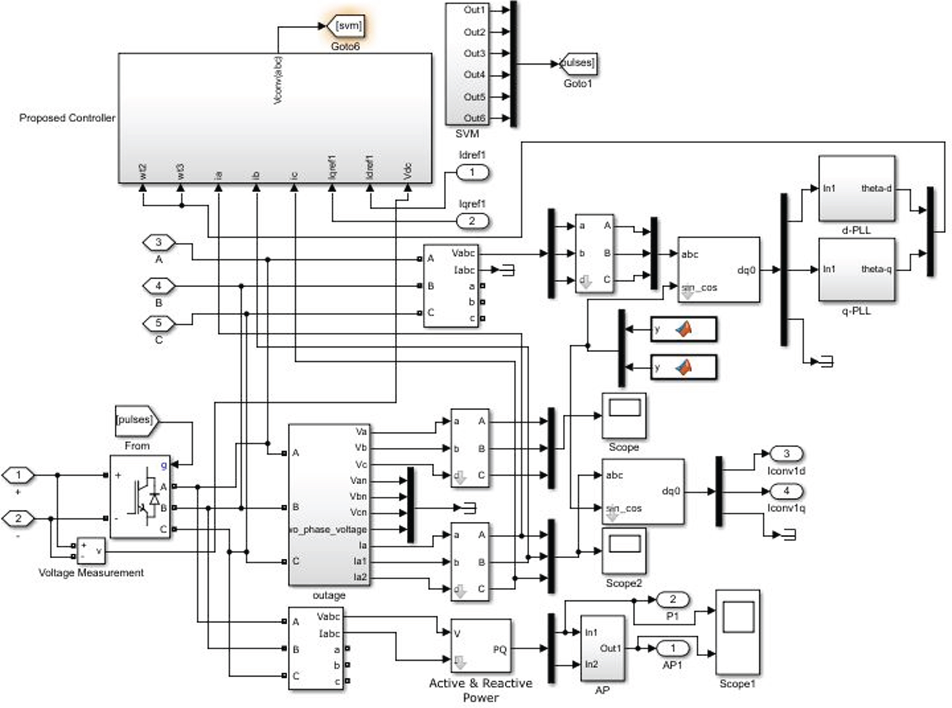
Simulation model of inverter.
Simulation model of the proposed controller.
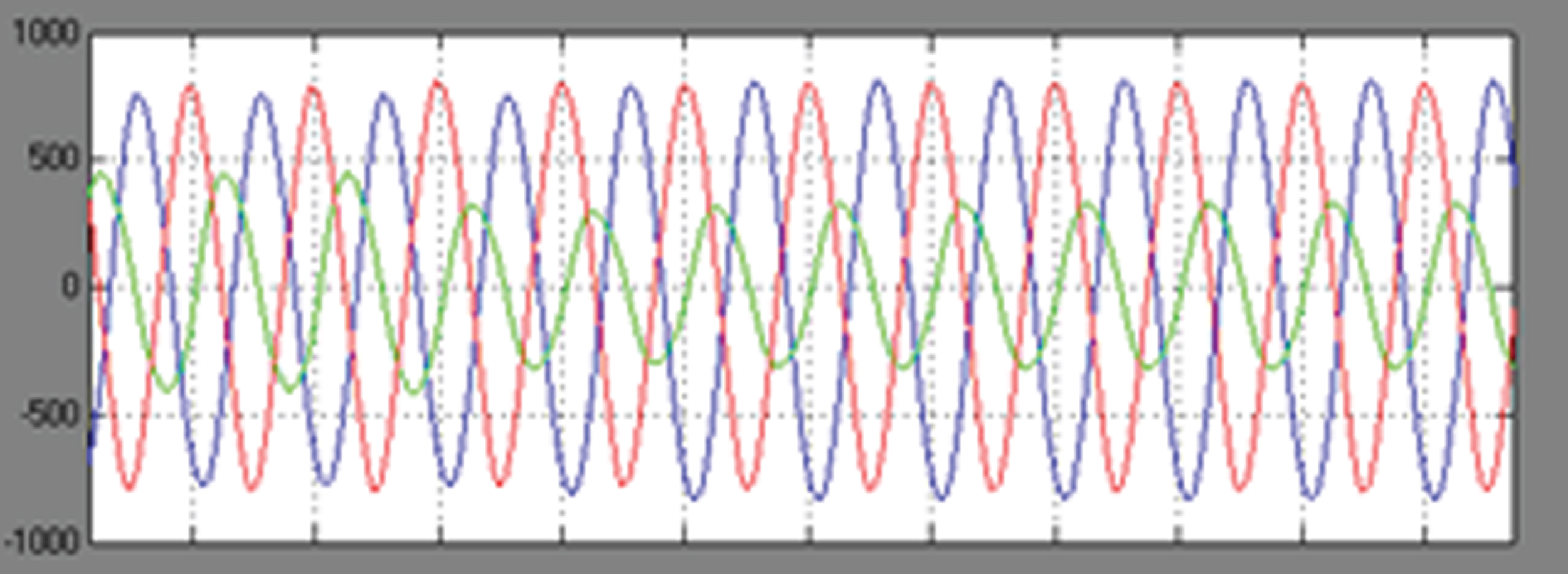
The output three phase voltage and current obtained at PCC with respect to time is shown in Figs. 8 and 9, which is sinusoidal and does not have any voltage spikes. So, the power quality of the system is maintained without fluctuations. Here, the THDV is reduced to 2.95% and THDI to 1.10% by using the MKES based controller design which is well within the limit as specified by IEEE 1547 and is evident from FFT analysis which is shown in Figs. 10 and 11. Also, the voltage controller is utilized to control the output voltage and frequency of the PV inverter.
Phase voltage at point of common coupling.
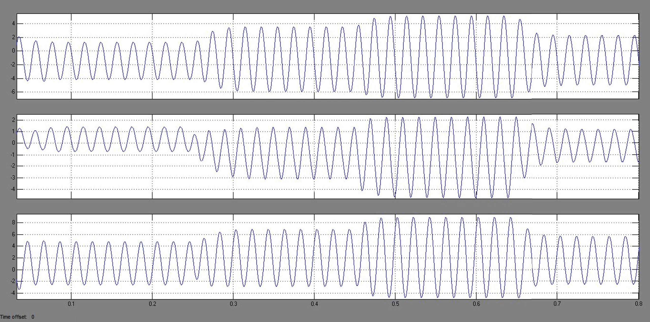
Phase current at point of common coupling.
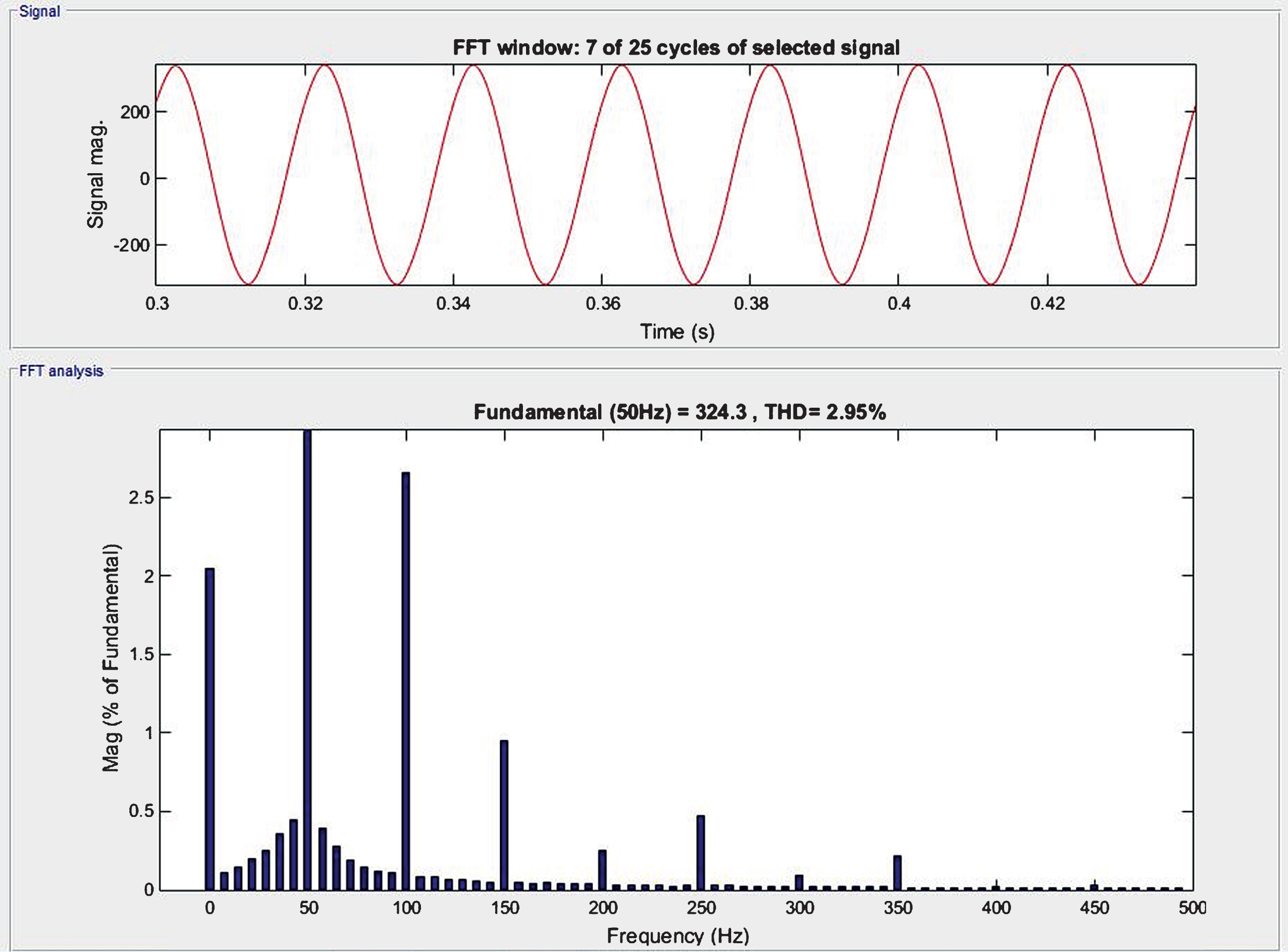
Total harmonic distortion – voltage for phase voltage at PCC.
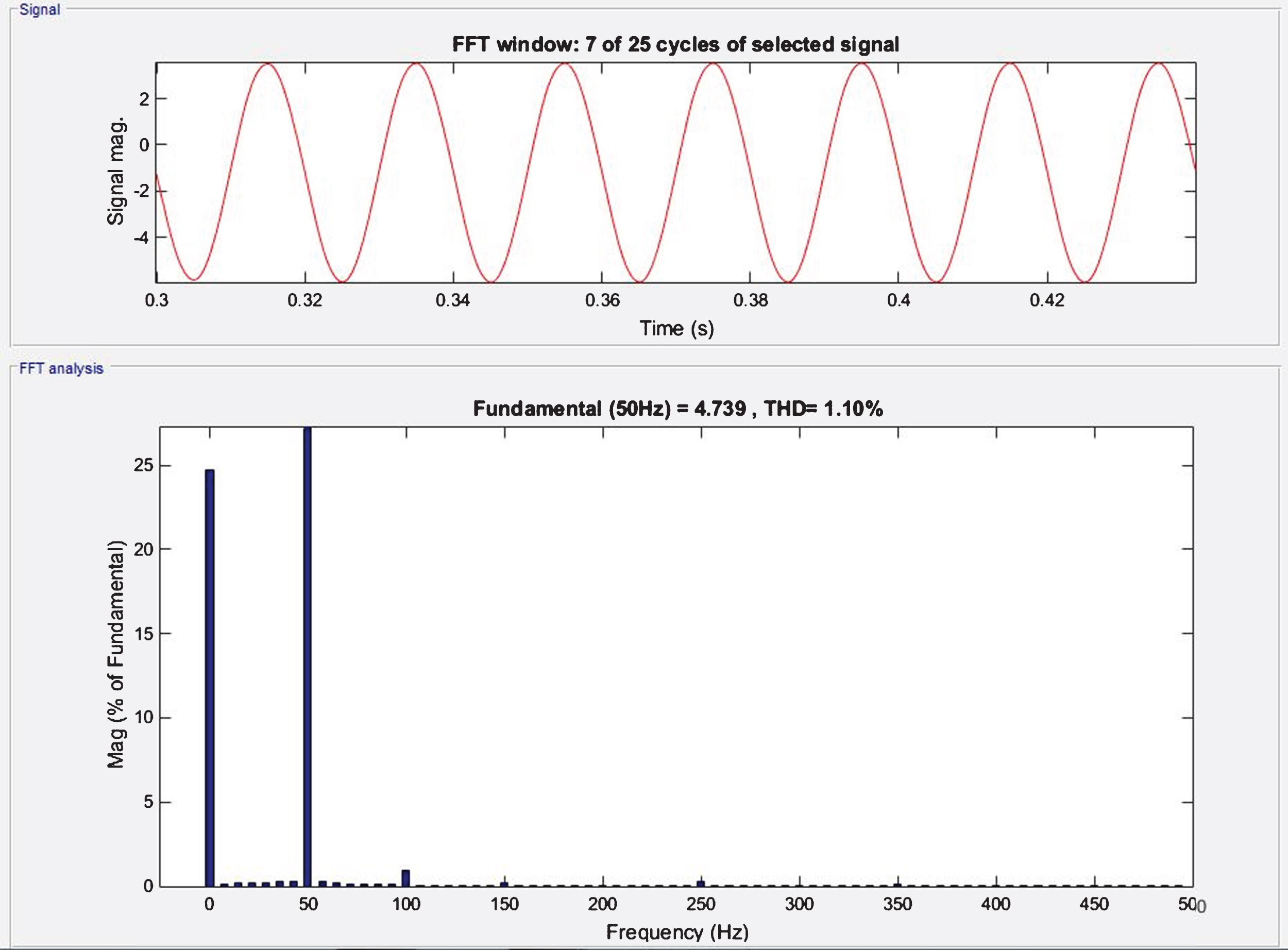
Total harmonic distortion – current for phase current at PCC.
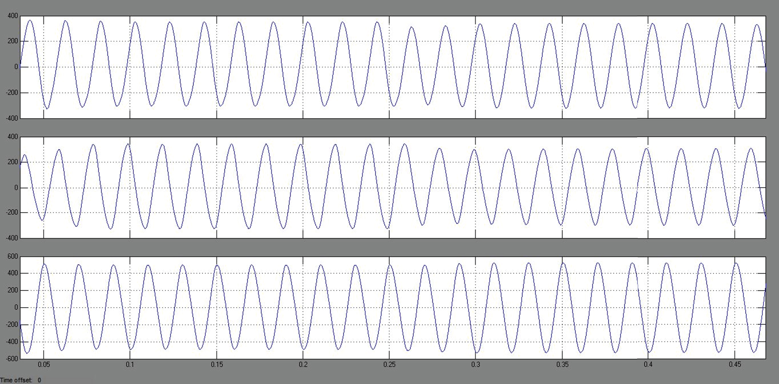
The active, reactive and apparent power of inverter 1 and inverter 2 are estimated as shown in Fig. 12. The active power is defined as the product of voltage across the load and its flow of current. If the circuit is totally resistive, it is estimated as follows:
Active, reactive and apparent power of inverter.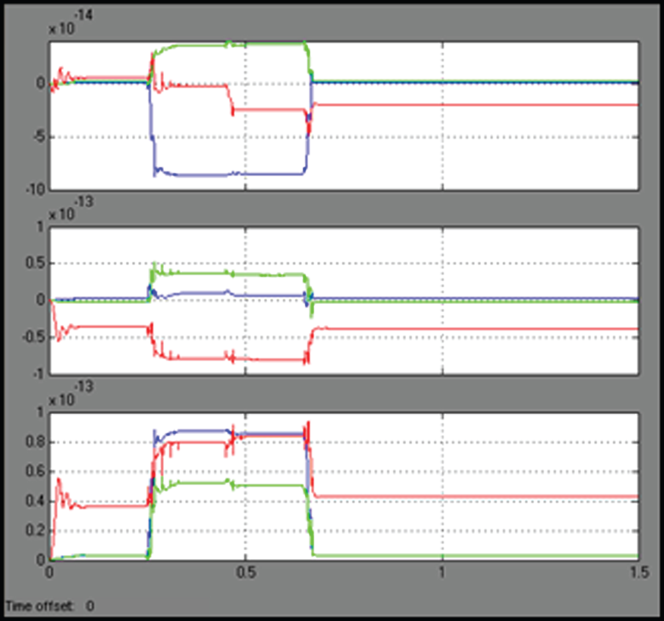
Moreover, the apparent power is estimated based on the combination of both active and reactive power supply to the circuit. It is the product of current and voltage, which is shown below:
In Equation 4, APR indicates the apparent power, AP indicates the active power, and RP indicates the reactive power. From this analysis, it is observed that the active, reactive and apparent powers of both inverters are maintained in an efficient manner.
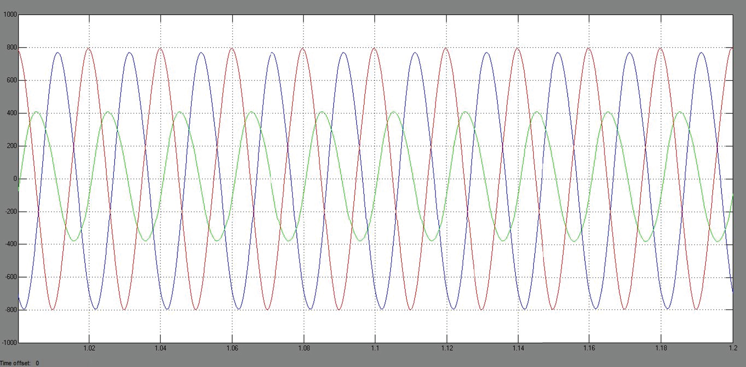
The grid voltage waveforms of the three phase inverter is shown in Fig. 13, where the x-axis denotes the time in terms of seconds and the y-axis denotes the voltage in terms of volts. The grid voltage is mainly analyzed to examine the fluctuations in the power system. Moreover, the power quality of the inverter is verified in both on and off states. In this investigation, it is proved that the grid voltage is maintained without fluctuations.
Grid voltage.
The output voltage of both inverter 1 and inverter 2 is depicted in Figs. 14 and 15, where the x-axis indicates the time in seconds and y-axis denotes the voltage. In this design, the PI controller is used to perform the voltage regulation. Here, the output voltage is mainly estimated to analyze the effectiveness of the inverter’s output. Typically, the AC voltage is depicted in a sinusoidal waveform, so the output voltage obtained is in a sinusoidal form with improved quality.
Output voltage of inverter 1.
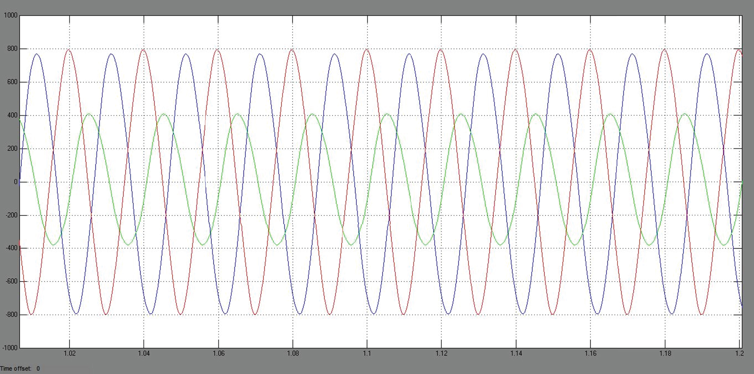
Output voltage of inverter 2.
In order to validate the effectiveness of the control strategy and controller, an 850 VA grid-connected three-phase inverter was experimentally tested. A switching frequency of 10 kHz was utilized for the inverter operation with IGBT CT60AM and driver IR2110. The proposed evolution algorithm based control strategy was implemented using the dsPIC 30F2010 with a sampling frequency of 20 MHz. The circuit schematic of the experimental system is shown in Fig. 16. The voltage drop across the current shunt is measured by using the integrated circuit 1NA168 which produces an analog voltage signal, which is directly proportional to the current. The current shunt is connected at the output current path.
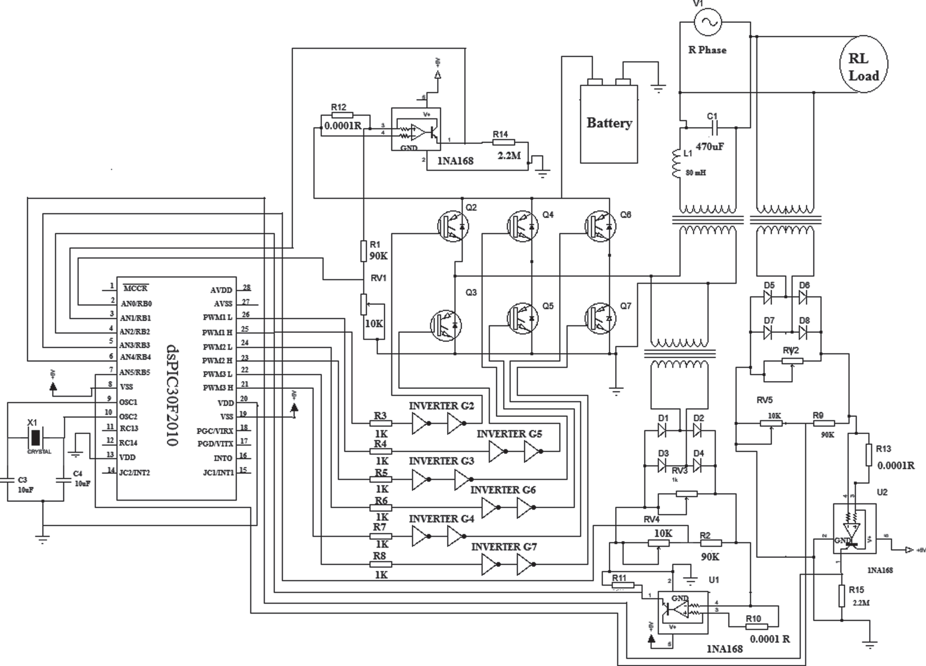
Circuit schematic of the experimental system.
The voltage input (feedback) to the dsPIC controller is given by a potential divider provided at the rectified output of inverter, load. In this way the Voltages and Currents of the system are measured and feedback to the controller platform for generation of reference currents and gate pulses to the switches of the inverter. Laboratorial hardware prototype setup of the system with load condition is shown in Fig. 17.
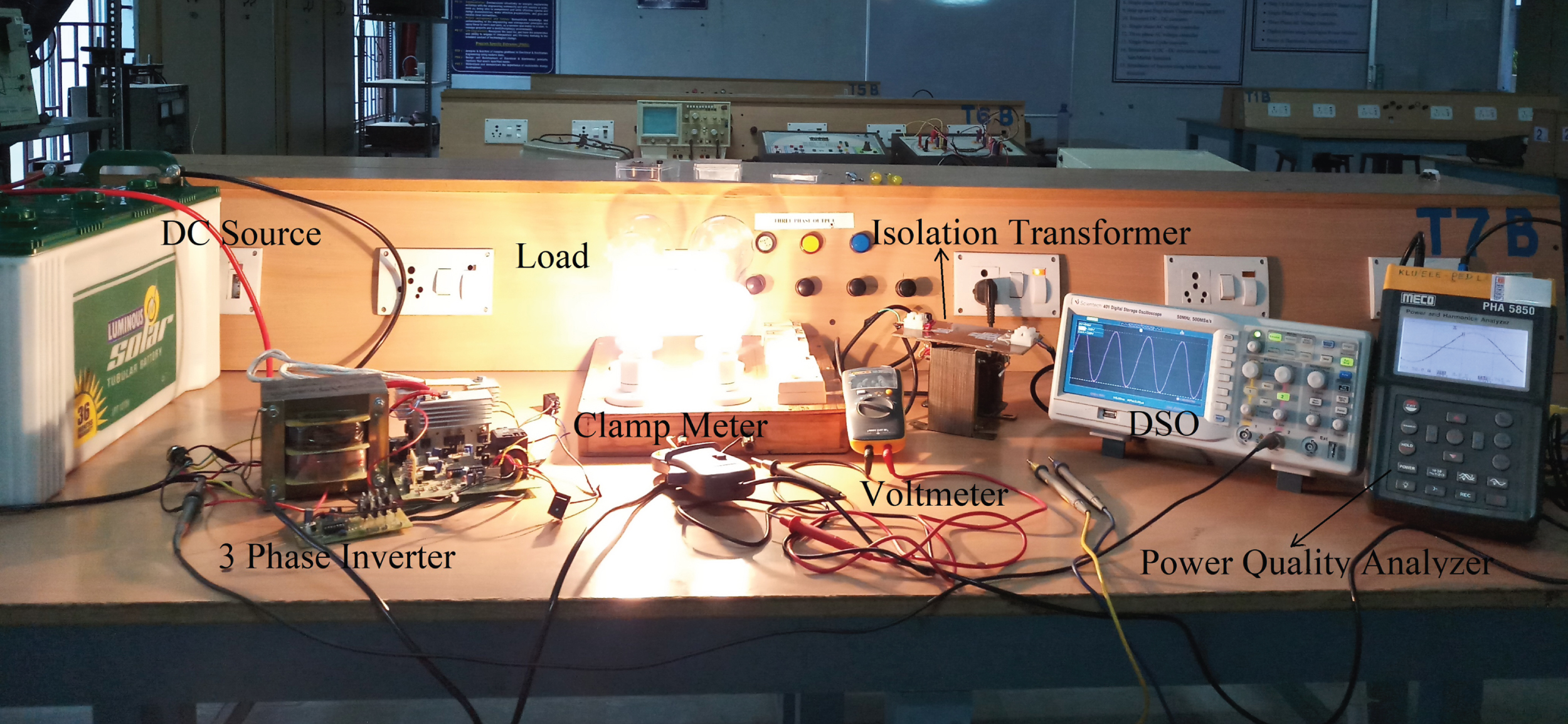
Laboratorial hardware prototype setup in loaded condition.
The VAr injection into the grid is provided by the inverter DC voltage source through a step-up transformer. Figure 18 shows the experimental outputs of gate pulse for triggering inverter switches and Fig. 19 shows the output voltage of inverter connected to the grid with load.
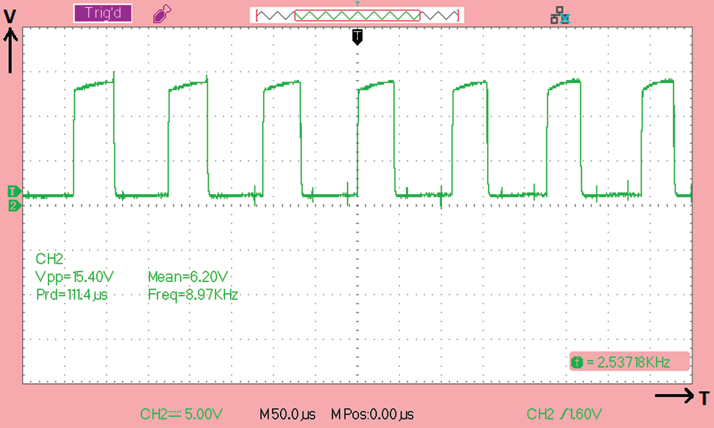
Experimental outputs of gate pulse for inverter switches.
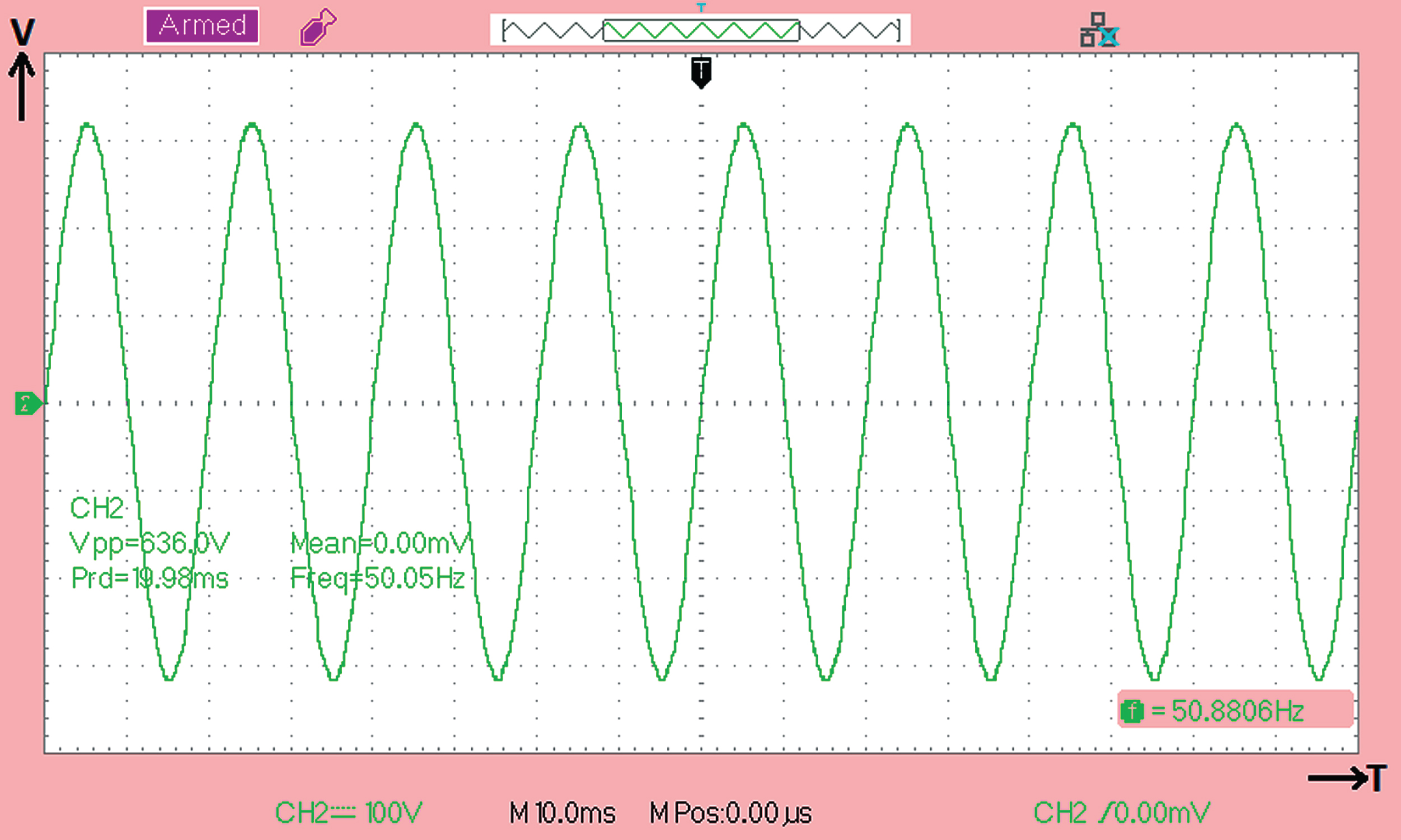
Experimental result of inverter output voltage.
Figure 20 shows the peak to peak output Voltage (Vpp= 443 V) of inverter with resistive load of 120 W connected to the grid. Figure 21 shows the peak to peak output load Current (I l=0.511A) of inverter with resistive load of 120 W connected to the grid. Both the output voltage and current waveforms are found to be sinusoidal with no distortions in them, thus ensuring the enhanced power quality.
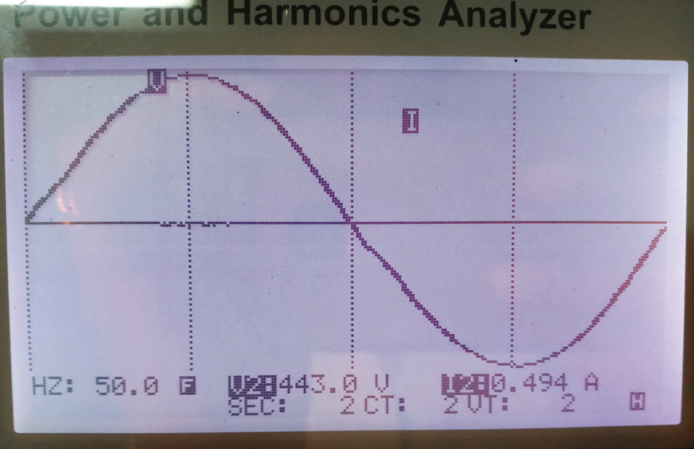
Experimental result of output voltage of inverter in power analyzer.
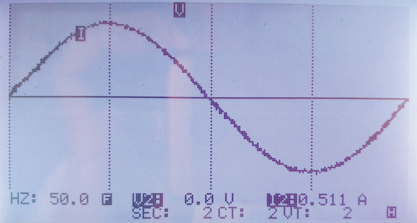
Experimental result of load current in power analyzer.
The authors have developed a robust controller using Monkey King Evolution Strategy technique for the governance of grid connected inverter, which is found to be the first of its kind. The technique has resulted in increased efficiency and performance of the grid connected inverter. The motive of this paper is to control the inverter without affecting its output voltage. Also, it focuses to overcome the drawbacks of the traditional controlling techniques by improving the performance that includes direct power control, and voltage oriented control. In the proposed technique, a four number of monkeys are initialized, which estimate the optimal solution based on the parameters of real power, distorted power due to load, reactive power of load and apparent power of inverter. In this technique, the monkey king collects the optimal solutions from all the monkeys and based on this information, a best solution for reference current generation is opted. Further, the PI controller is used to regulate the voltage at a constant level and SVM is employed to generate the pulses for inverter. This technique attains an enhanced power quality by using a multi-function grid connected inverter, which acts as an interface between the energy resource and load. The major benefits of the proposed controller are good dynamic response, increased robustness and reliability. During simulation, the performance of the system is analyzed based on the different power quality analysis measures. From the experimental examination, it is observed that the proposed MKES based controller provides better results of output waveforms with increased power quality.
In future, this work can be enhanced by implementing a new soft-computing technique for voltage sag compensation as stringent grid codes demands connectivity of system to the electrical network even in voltage sag conditions [34].