
Abstract
The intelligent tracking car can realize self-perception, behavioral decision-making, automatic driving, etc. for environmental information, and has a wide application in our lives. In this paper, a new intelligent car is designed based on STM32F407ZGT6 MCU. The track information is collected by the OV7725 camera. The fast OTSU adaptive threshold algorithm is used to obtain the path guiding center line, which can realize image collection, image analysis and sensor data fusion, blocked path identification and intelligent judgment, automatic tracking function. The test results show that the algorithm is effective and feasible. When there are obstacles or partial loss on the track, it can intelligently identify the effective and obstacles and realize the independent decision making. It has good dynamic and robustness.
Introduction
Intelligent car has been widely used in many fields because of its convenience and even can replace people to complete highly dangerous work, which shows great superiority. At present, the research of mobile robots has been paid more and more attention in various countries, varying from hardware construction to soft programming and from sensor networks energy saving [1, 20] to secure transmission of data[2–5].
As the basic platform for the research and testing of mobile robots, intelligent car has made a series of corresponding achievements [6–10]. With the emergence of concepts such as machine vision and artificial intelligence, image-based driverless technology is one of the current research hotspots [11]. Wang improved the Back Propagation network algorithm and established AGV visual system to recognize the road sign [12]; an innovative two-dimensional vision sensing method was used for a four-degree of freedom (4-DOF) robot arm to grip a moving target on a moving platform [13]. Even the blurred image, which is a problem when the visual guidance vehicle used to locate a two-dimensional code, can be processed by blurred image restoration algorithm based on the optimal number of iterations [14]. The application of machine vision in intelligent car mainly involves image acquisition, image processing, target recognition and navigation control [15]. It is one of the important means for mobile robot to perceive the external environment and obtain information.
In this paper, based on STM32F407ZGT6 single-chip microcomputer as the control core, the OV7725 digital camera is used to collect path image information, the moving direction and speed of the car are calculated through image analysis. By adjusting the speed of the wheel, the car can move correctly according to the guiding path. Moreover, intelligent obstacle avoidance and path planning can be realized under complex path conditions as well by obstacles recognition and path compensation.
Overall structure of the system
The control core of intelligent car is STM32F407ZGT6 MCU, which realizes information processing, motion decision-making and motion control. The OV7725 digital camera is used to collect path information. When the path image is saved, the camera will transmit it to MCU. The MCU performs deep processing and decision on the data to obtain the offset of the driving track. Under the action of the PWM module, the control signal is transmitted to the BTS7960 motor drive module to adjust the speed and steering of the four motors. When the ultrasonic, infrared and other sensors of the car detect obstacles, the obstacle avoidance module is used to obtain the environmental information until the vehicle avoids the obstacle and returns to the normal trajectory guide line, thereby completing the obstacle avoidance during the tracking process. The motion platform adopts the Mecanum wheels with excellent maneuverability and flexibility, which can realize four-wheel drive such as forward, translation, oblique line and rotation, thus improving the obstacle avoidance function of the car. The overall framework of the hardware platform is shown in Fig. 1.
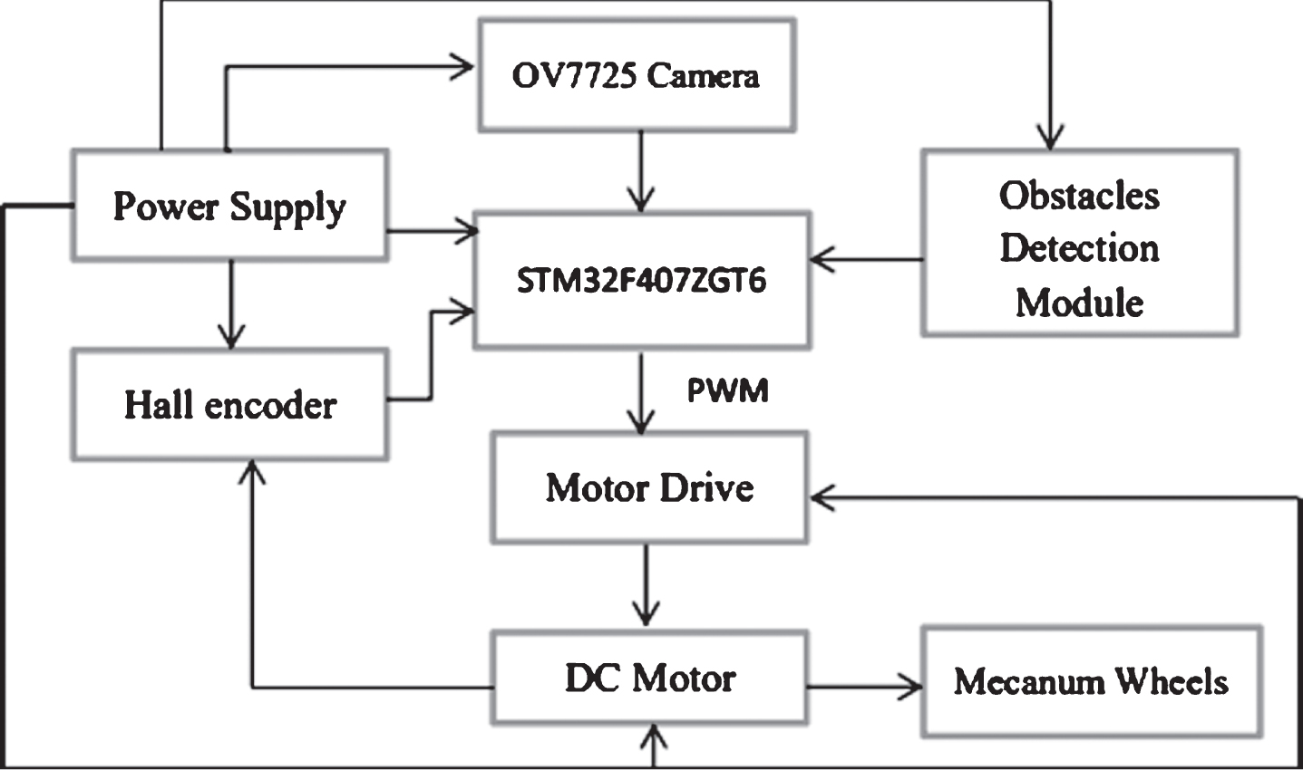
Overall framework of the hardware platform.
Core control module
The single-chip computer system is the core control module of the smart car, and is also the most critical module. Therefore, the performance of the single-chip system directly determines the performance stability of the whole platform. STM32F407ZGT6 MCU system has advanced Cortex-M4 CPU and up to 1M FLASH and 196K embedded SRAM. It has abundant I/O interfaces and registers as well. The processing capacity of 210 DMIPS and processing speed of 168 Mhz, and abundant peripherals guarantee a better reliability of the system. Because of its high performance-price ratio, powerful function and convenient use, STM32F407ZGT6 single-chip computer is selected as the core controller in this system to process image information effectively, and judges the feasible path according to the image analysis result to determine the motion track and parameters such as trajectory, steering and speed. The PWM wave is output to control the motion of the intelligent car, which ensures that the car can work steadily according to the trajectory.
STM32 has lots of wiring ports, and some I/O ports can be reused. Reasonable allocation of the STM32 ports is an important part of the automatic obstacle avoidance control system. The allocation status of STM32 is shown in Table 1.
Ports allocation of the STM32F407ZGT6
Ports allocation of the STM32F407ZGT6
Image acquisition is one of the main function modules of intelligent vehicle based on vision to obtain path information. In order to reduce the complexity of hardware system, enhance the independence of module circuit, and improve the stability and cost-effectiveness of the system, OV7725 digital camera is selected in this system. The camera integrates sensors, active crystal oscillators and FIFOs with high image quality, standard SCCB interface and IIC interface. It has rich output format and low power consumption, supports automatic exposure and image scaling, and can meet the image acquisition requirements of this system. After OV7725 collects the image, the image is stored in the FIFO module, and then the FIFO image data is read by the single chip compute.
Motor and drive module
Motor modules are very important actuators. ZGB37-520B DC motor with Hall sensor is selected in this paper, rated voltage 12 V and rated speed up to 1000 rpm. When the power supply of Hall sensor is turned on, the Hall sensor outputs A-phase and B-phase pulse, and the two-phase is separated by a half cycle pulse, which can be used to detect the positive and negative rotation. For the Hall sensor of the ZGB37-520B motor, the motor outputs 12 pulses per revolution. The pulse frequency can be calculated by capturing the pulse, so as to know the rotation speed of the intelligent car, and thenfeedback.
According to the motor parameters, the high-power drive BTS7960 chip is selected as the motor drive module. The module has overheating and overcurrent protection functions, and also has powerful driving and braking effects. The circuit diagram of the motor and drive module is shown in Fig. 2.
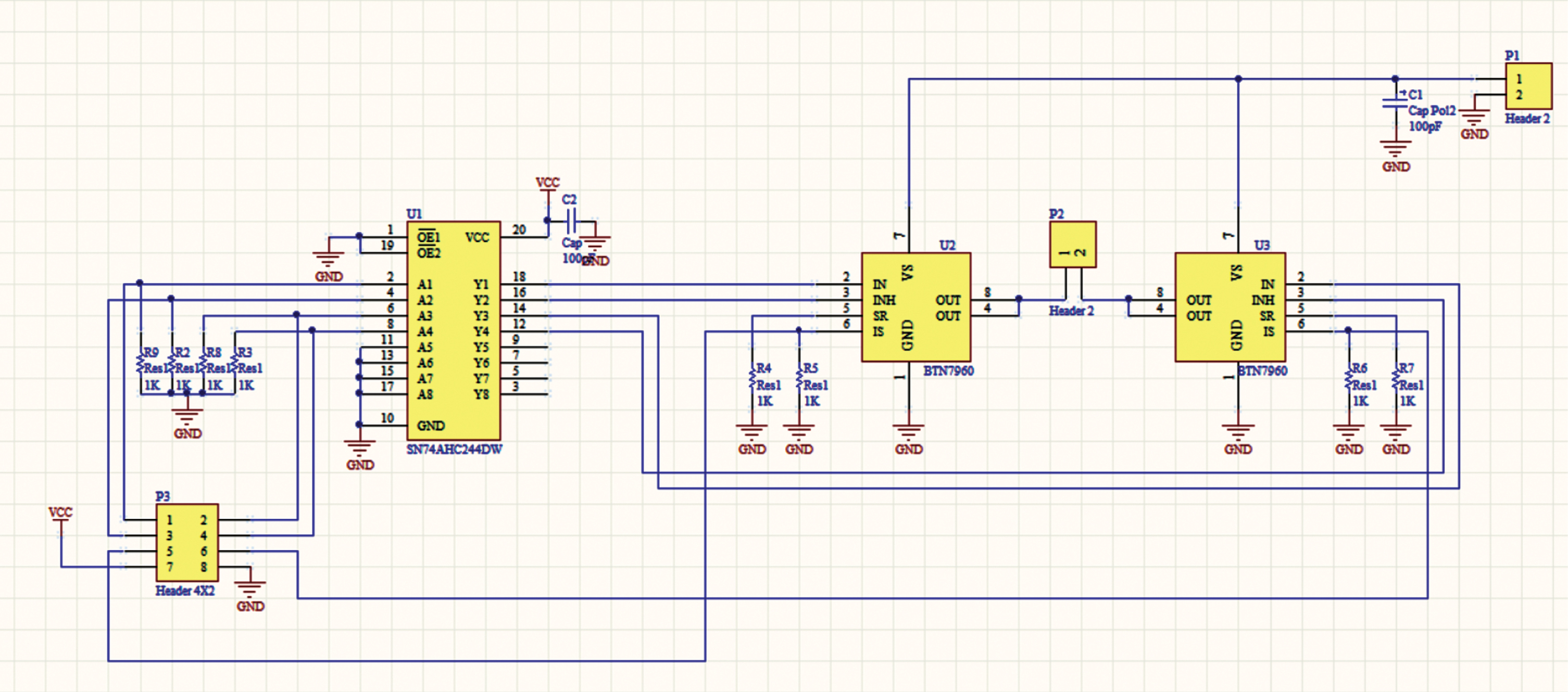
Circuit diagram of the motor and drive.
The obstacles detection module contains several ultrasonic sensors HC-SR04 and infrared sensors, which can effectively measure the position information of obstacles and transmit the signals to the MCU to calculate the direction and speed of the next car movement. Among them, the circuit diagram of the ultrasonic ranging module is shown inFig. 3.
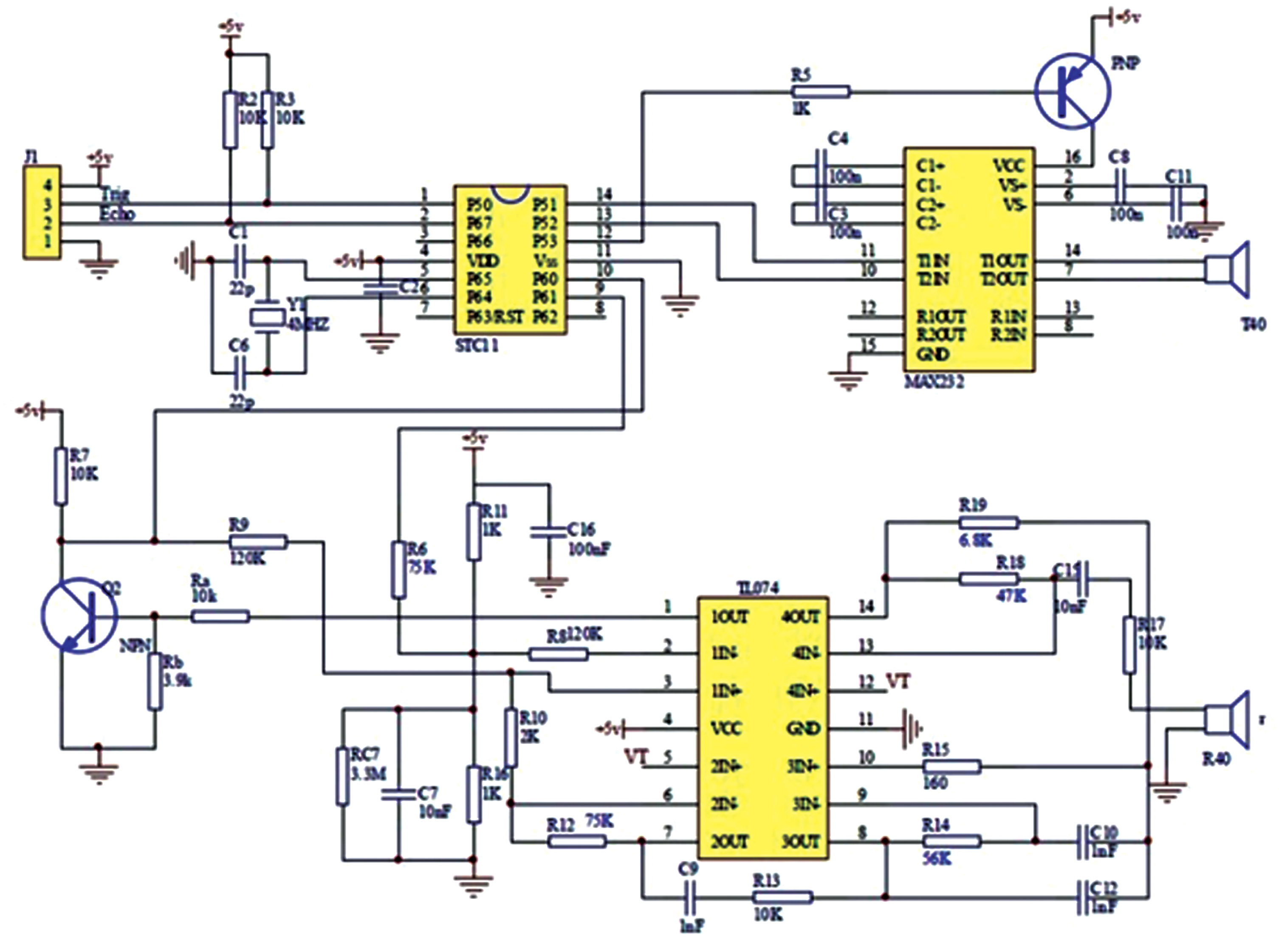
Circuit diagram of the ultrasoniic sensor.
The power supply module mainly provides stable voltage for the single chip computer system, OV7725 camera, BTS7960 motor drive and other modules. For the motor, the power supply voltage has a certain relationship with the speed. Therefore, when setting the power supply module, the voltage and current should be taken into account comprehensively, requiring its efficient conversion and improving the anti-interference of the power supply. Therefore, a fixed-wing 5300 RC battery with 11.4 V 2200 mAh and a 5 V rechargeable battery are used to form the power supply module. Fig. 4 shows the voltage applied to each module. The rechargeable battery output voltage is 5 V, which can be lowered to 3.3 V by a specific device, while the motor is directly powered by the 5300 RC battery.
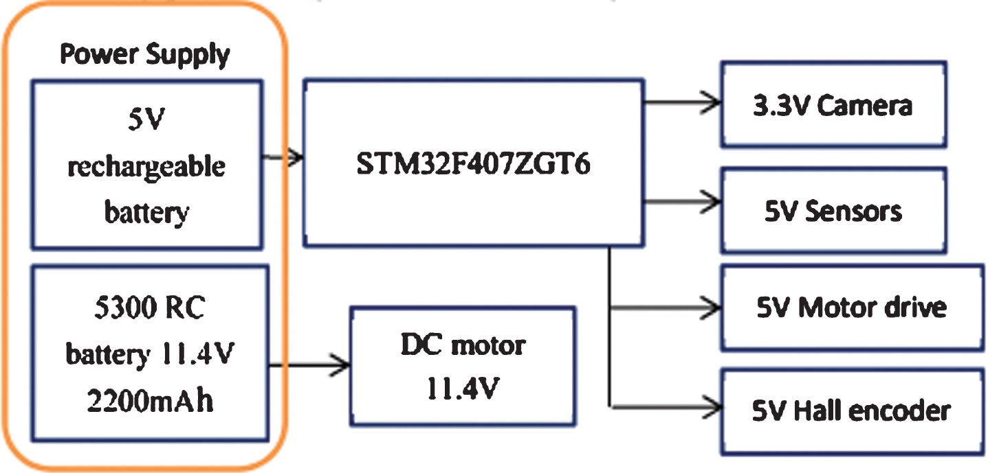
Power supply distribution.
In the test, the information in the camera can be observed in real time through the LCD display screen. The LCD module is TFTLCD, the display driver is LIL9341, the data transmission format between LCD and camera is RGB565, the display resolution is 240*320, which matches the resolution of QVGA image.
Mecanum wheels
Because the Mecanum wheels are extremely maneuverable and flexible, special Mecanum wheels are used in this platform. According to the wheel structure, it is possible to control the speeds and the direction of the four Mecanum wheels such as forward and backward movement, left and right movement and rotation, and realize four-wheel drive such as forward, horizontal, oblique, and rotation, thereby improving the obstacle avoidance performance of the car. Since the intelligent car has four Mecanum wheels, it should use eight PWM wave outputs to fully control the speed and direction of the four Mecanum wheels. When four wheels are given the same speed in different directions, the car can achieve displacement in various directions(see Fig. 5). The four Mecanum wheels are in O-rectangular installation(see Fig. 6).
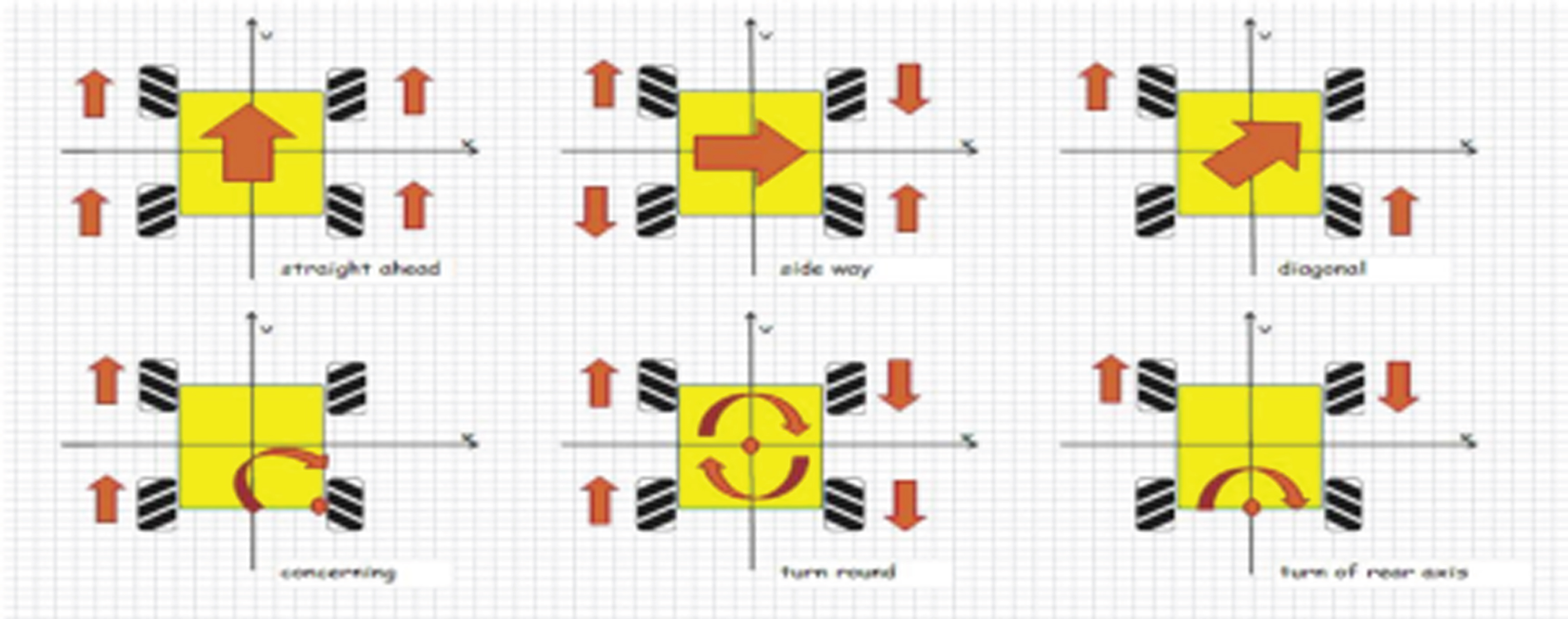
Directions of Mecanum wheels.
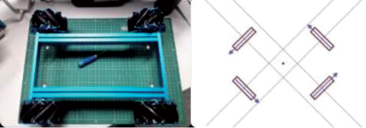
O-rectangular installation of Mecanum wheels.
Finally, the specific layout of the car body hardware is shown in Fig. 7. The camera is installed at the front of the car, maintaining a tilt angle of 30° with the ground to ensure high quality of road surface information. The motor drive modules are respectively installed at the four corners of the car chassis. Because it is an aluminum alloy chassis, the radiator can be directly fixed downward and installed symmetrically. The power supply modules are installed in the middle of the bottom of the car. The MCU module is over the power module, raised by four nylon columns to reserve a certain installation space for the power supply to facilitate charging. The ultrasonic module is placed in the middle of the front of the car, and cannot block the field of view of the camera. The infrared modules are installed at the four corners of the chassis, assisting the left and right translation to avoid obstacles.
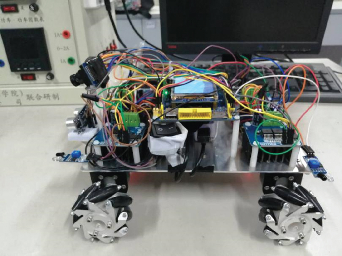
Overall of intelligent car.
An efficient and stable software system is the core of the stable operation of intelligent car. The system obtains the path information through the camera module, and the encoder detects the real-time speed of the intelligent car. After the analysis and calculation by the single-chip computer, the corresponding PWM waves are output to control the speed of the wheels, and the moving direction of the car is adjusted, so that the car can track correctly. Moreover, when the path is incomplete or passing through the intersection, the correct decision can be made. When encountering unknown static obstacles, the obstacles can be avoided.
Therefore, the system software design mainly includes the speed feedback control of the wheels, the path image information collected by the camera, the path center line extraction, the obstacle avoidance and the effective path determination algorithm. The flow chart of main program of the system is shown in Fig. 8.

Main flow chart.
In this system, both obstacle avoidance and tracking require high speed accuracy of the car. Especially when considering the special structure of the Mecanum wheels used in this platform, the accuracy of the speed is more precise than the ordinary wheels, so the speed control of the car is particularly important.
There are several rollers on the circumference of the Mecanum wheel. The axis of the wheel is at an angle of 45° to the axis of the roller. The rollers are independent of each other and can rotate freely. The force analysis of the four Mecanum wheels installed by O-rectangle during motion is shown in Fig. 9.
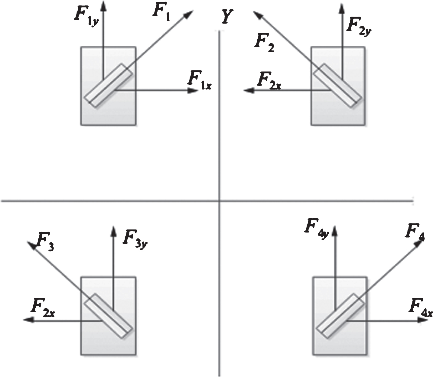
Force analysis of a group of 4 Mecanum wheels.
Kinematics theory is used to analyze a single Mecanum wheel (see Fig. 10). R represents the radius of the wheel; V ix is the speed of the i-th wheel along the X-axis (m/s); V iy is the speed of the i-th wheel along the Y-axis (m/s); V g is the speed of the roller (m /s), that is, the rotational speed (rad/s) of the omnidirectional reel axle. i = 1,2,3,4 respectively represent the left front wheel, the right front wheel, the left rear wheel, and the right rear wheel [16].
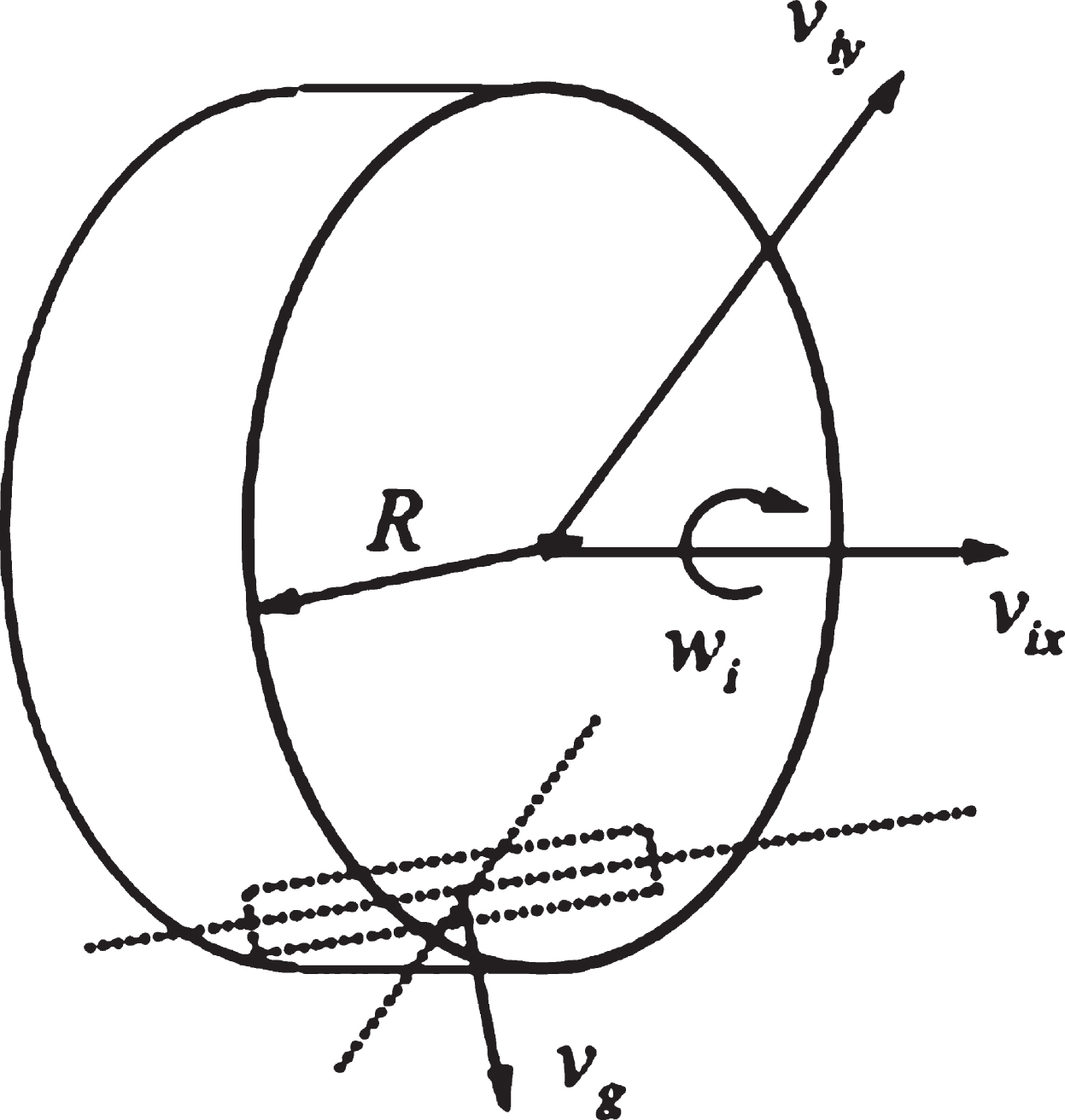
Force analysis of a single Mecanum wheel.
From the kinematic analysis, the speed of the wheel is
a = 45° when i = 1,4 while a = –45° when i = 2,3 [16]. Substituting the Equation (1), we have
In Equation (2), a = 45°, l0 = W + l cos α, W represents the width of the intelligent car, l represents the axle distance between the front and rear wheels [16]. Its inverse kinematics equation is
Where, K is the inverse kinematic Jacobian matrix, rank(K) = 3.
There are two main parts of car speed control by PWM waves, firstly, set the duty cycle of the PWM to change the speed, secondly, capture the signal generated by the Hall encoder to perform feedback control. PID control is the most extensive regulator control law in engineering applications, with simple structure, reliable operation and convenient adjustment. The PID formula is written as Equation (4).
This PID control algorithm is calculated based on the deviation of the current state value from the preset value. The resulting output is related to the past state because the error accumulation is used. When the output u (k) error occurs, it will affect the position change of the actuator.
Therefore, this paper adopts PID incremental control algorithm(see Equation (5)).
The algorithm is based on the latest error increment rather than the deviation of the actual position deviation, that is, there is no need to increase the incremental PID. The determination of the control increment u (k) is only relevant to the last three sample values. It is easy to obtain better control effects by weighting. When the system fails, the incremental system will not seriously affect the system’swork.
In the process of image acquisition, because the FIFO memory of the camera is 380 kb, we chooses the resolution of QVGA (320*240), which can grasp the details well for MCU processing. There are mainly three steps.
First, the image is collected by camera and stored in the FIFO. The frame image in FIFO is read out by MCU, and displayed on LCD screen after graying and binarization.
Then, the pixels in the middle of the display screen are processed to determine the position A and B on the left and right sides of the track by judging the position of the black points. Thus, the center of the track (A + B)/2 is obtained. In order to make a more accurate judgment, the system also collects and assists the black pixels on the left and right sides to assist in judging the track condition.
In the third step, the deviation is obtained by subtracting the coordinates (A + B)/2 of the track center from the coordinates of the screen center 160, and then determining the road condition by the number of black pixels around the screen center.
Because the human eye is different in sensitivity to images, green is the most sensitive and blue is the least sensitive. Therefore, the weighted average method is used to generate a more reasonable gray image, that is, multiplying the three components of RGB by different weights. The weighted average gray processing is expressed in Equation (6).
Where, R (i, j), G (i, j), B (i, j) are red, green and blue components at coordinate points (i, j), f (i, j) is the gray value, range from 0 to 255.
Image binarization is the process of obtaining the overall and local features of an image by selecting appropriate thresholds on the gray image. It makes the image simple and highlights the outline of the target, which is to show the entire image a distinct black and white effect. Let the output binary image data be g (i, j), then
Where, threshold is the image threshold, which is selected by using a fast OTSU adaptive threshold algorithm [17–18]. If the threshold is selected well, the background and foreground of the image can be well segmented, and the binarization effect is obvious.
In addition to the basic tracking functions such as straight-forward and turning, the car can also implement autonomous obstacle avoidance and effective path determination under complicated road conditions such as obstacles on the track, loss of the track, and crossroads(see Fig. 11). The ultrasonic module is placed in the middle of the front of the car, marked as a red square. The infrared modules are installed at the four corners of the chassis of the car, marked as 4 blue squares(i = 1,2,3,4 represents infrared sensor of left-front, right-front, left-rear and right-rear respectively).
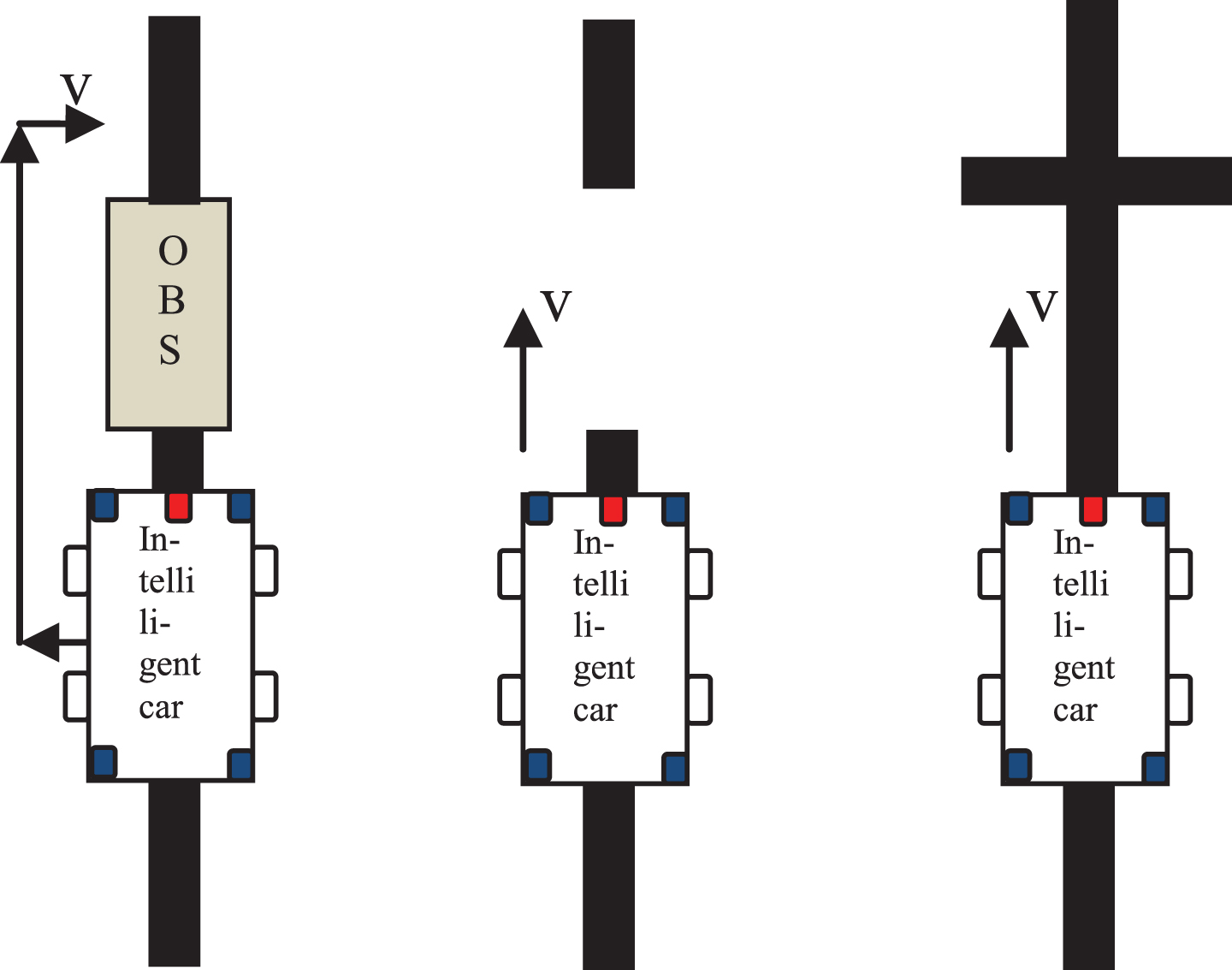
Obstacles on the track, loss of the track, and crossroads.
The system mainly detects obstacles through infrared sensors and ultrasonic sensors. When there are obstacles on the trajectory, the car moves to the left until the infrared sensor on the right front end of the car detects no obstacles within the safe distance, then the car moves forward until the infrared sensor on the right rear end of the car detects no obstacles within the safe distance, it stops, then moves to the right, cooperating with the camera image processing, until it returns to the original trajectory. Thus obstacle avoidance is completed. The flow chart of obstacle avoidance subprogram is shown in Fig. 12.
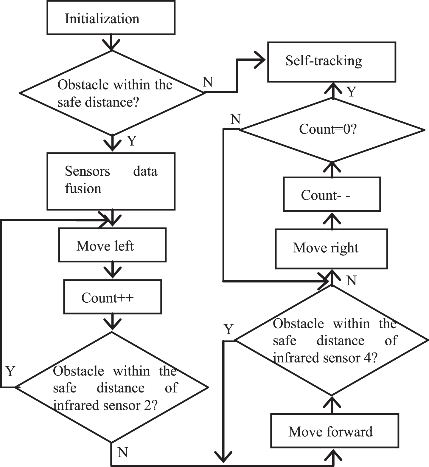
Flow chart of obstacle avoidance subprogram.
When the track is lost, the intelligent car will continue to move forward for a certain time to capture the next frame of track image for processing. The two track images will be compared. At the beginning we believe that the track loss for a short distance and will continue straight away for a short certain time. When the time is too long, we will consider the track is completely lost and the car stops. The flow chart of obstacle avoidance subprogram is shown inFig. 13.
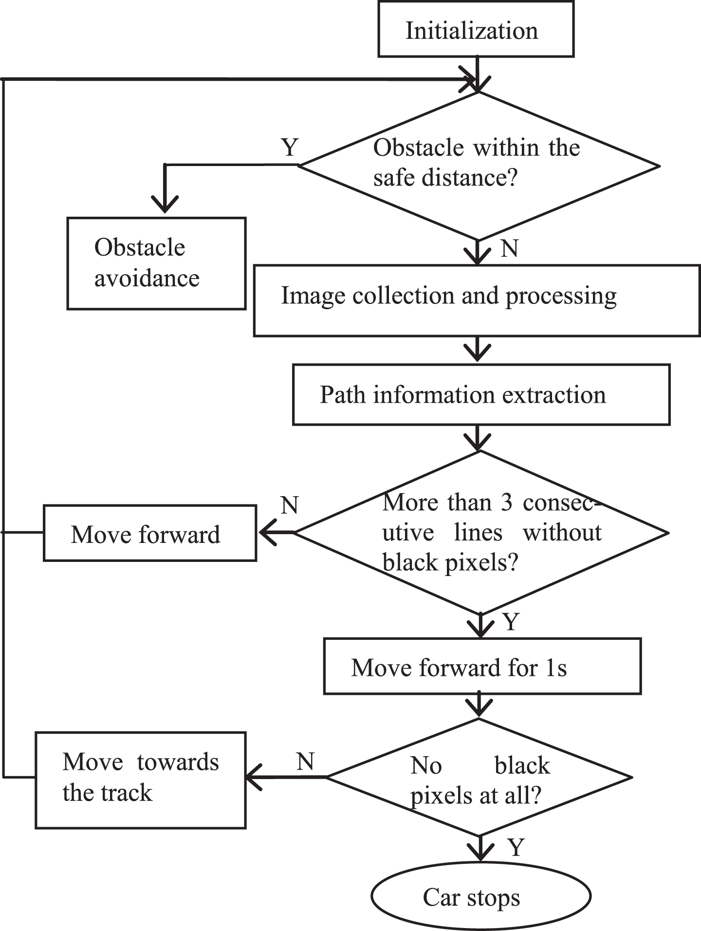
Flow chart of partial track loss subprogram.
Since the camera lens is spherical, the image pixels at the intersection are not a straight horizontal black line, but a certain degree of inclination. By studying the serial port data, it is found that the captured pixels are regular, increasing from the left pixel to the full and decreasing, while the right pixels are on the contrary, from decreasing to increasing. Therefore, this paper first captures the multi-pixel points on the left side and then captures the multi-pixel points on the right side.
The principle of judging a path as a T-junction or an intersection or a right/left turning is similar. Thus, cross-type conditional judgment is added to the right/left turning program in the tracking. We compare the two images stored in sequence, analyze the absolute value of the difference, and divide it into four categories: left turning, right turning, T-junction, crossroad. Among them, the left and right turnings will send different PWM waveforms to make the Mecanum wheels turn to the corresponding direction. If it is a T-junction, the priority is to turn left. And if it is a crossroad, the intelligent car will move forward straightly.
Experiments
As mentioned before, because the camera lens is spherical, the track displayed on LCD is in a small curve. Therefore, compensation is needed when processing image data. Normally, the intelligent car usually moves along the trajectory. As shown in Fig. 14-(a), the car is at the center of the track. The path image is displayed on the LCD screen in real time, as shown in Fig. 14-(b). The serial port data is shown in Fig. 14-(c). It can be seen that the estimated center of the car deviation from the trajectory is 3 pixels, so the car should continue straight ahead in this situation.
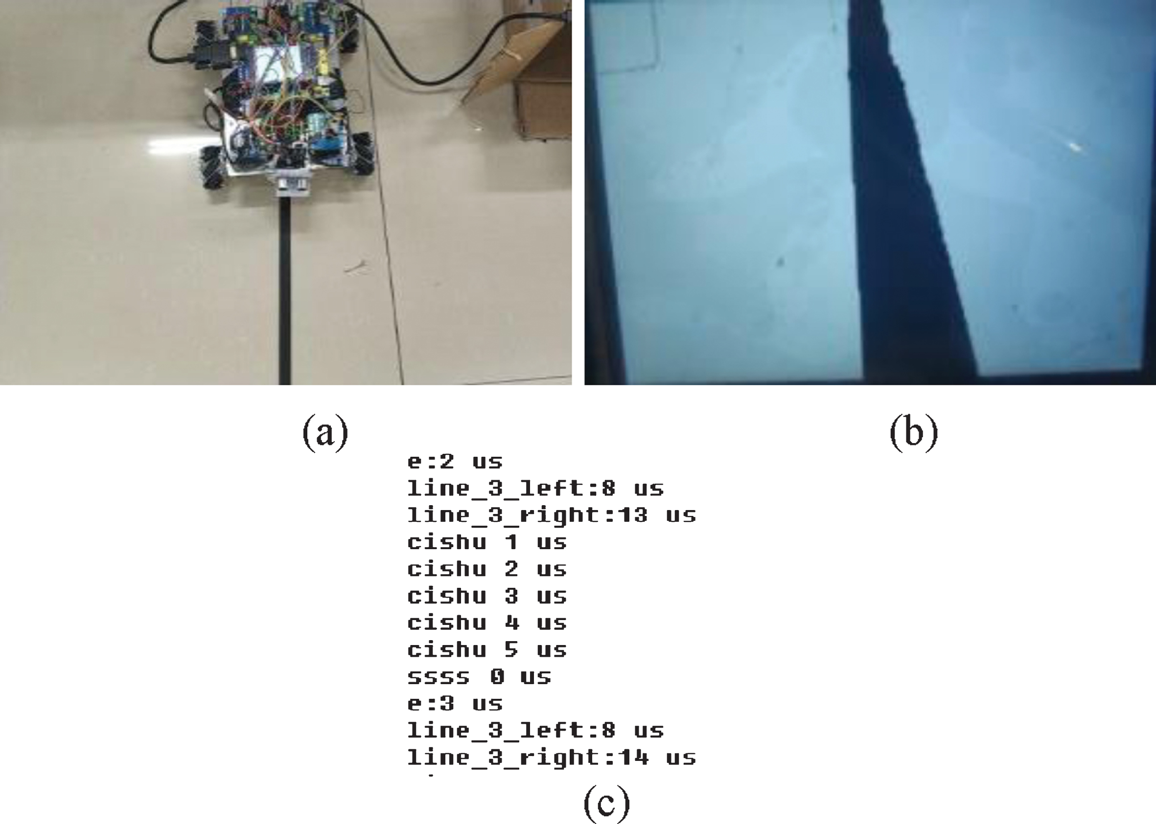
(a) Moving forward (b) Track on LCD (c) Serial port data.
When the car turns left or right, it will slightly deviate from the track just after the turning point. Fig. 15-(a) shows that the car is off track, on the left side of the track, and the deviation is large. It can also be seen from Fig. 15-(b) that the path displayed on the LCD is in the right part. We can find that the analysis error e has reached 122, which is shown in Fig. 15-(c), and the left pixel is 0, the right pixel is 27, therefore the black track is on the right side of the car. As a result, the duty cycle of the PWM wave output to the left and right wheels is different, so as to change the speed of the wheel to turn right and back to the track.
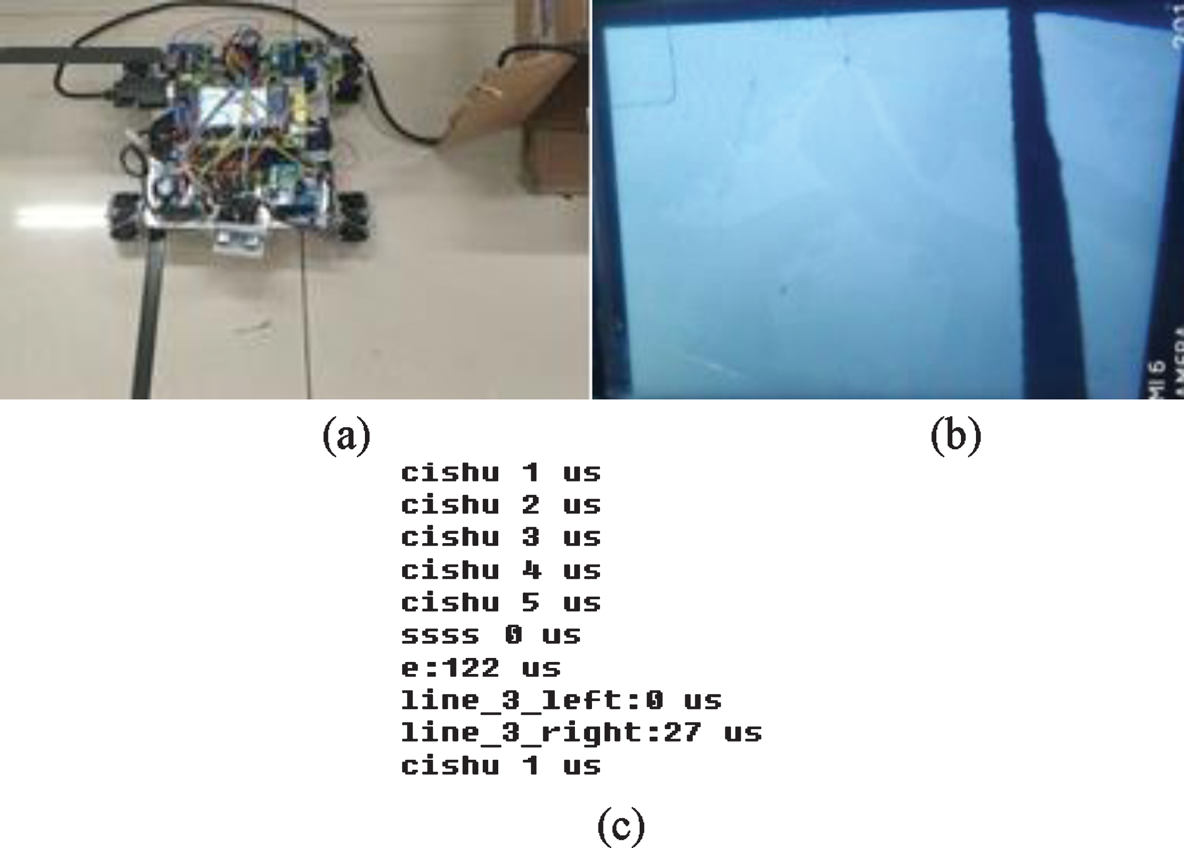
(a) Turning deviation (b) Track on LCD (c) Serial port data.
When the car passes the crossroads, it needs to compare the path images or judge by the conditional statement of the program. Only when the corner is continuously captured twice, the car turns. Otherwise the car won’t turn if the condition is not satisfied. In other words, the car will go straight through the crossroad. When the car is slow, the number of frames captured is enough for comparing. After the two frames of image data are subtracted, the path information in the same direction will become the next direction of the car. Both of the above conditions can make the car go straight through the crossroads smoothly. The practical testing results are showed in Fig. 16.
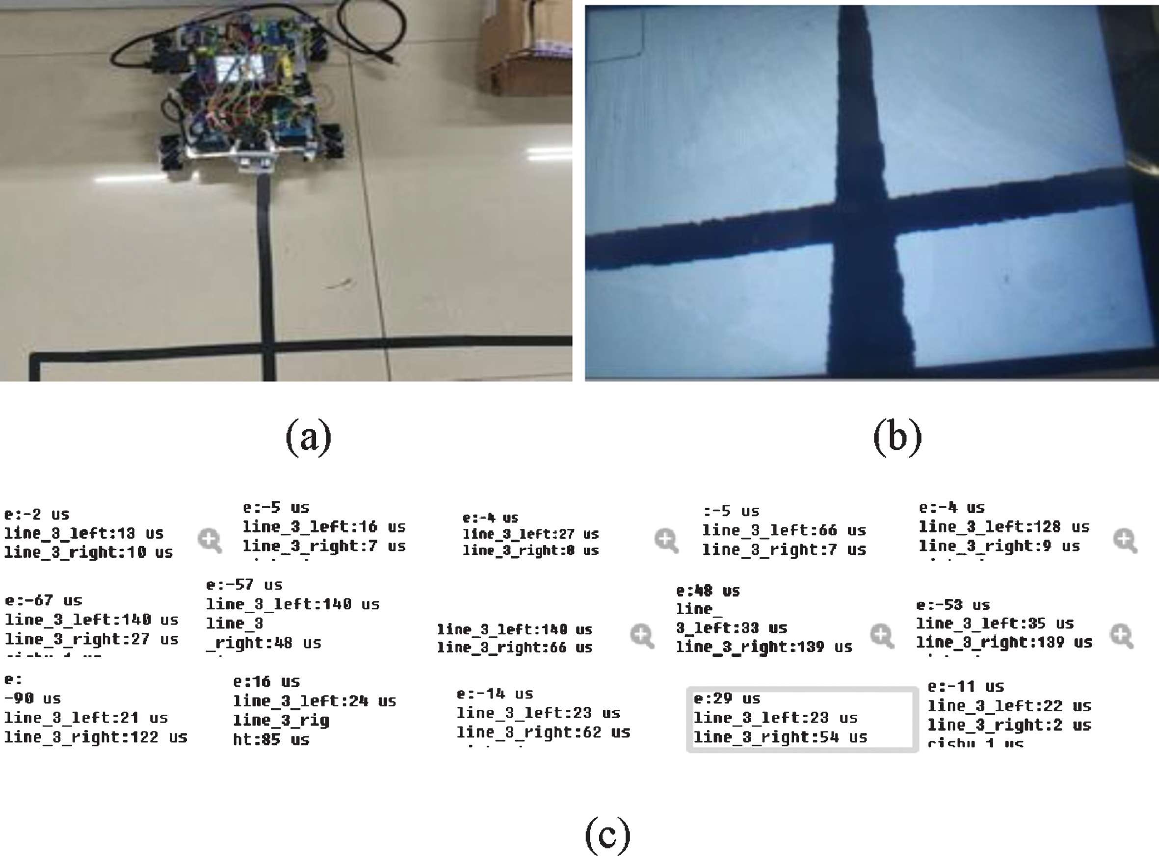
(a) Crossroads (b) Track on LCD (c) Serial port data.
From the above experimental testing, the intelligent car performs well and proves the algorithm is effective and feasible. However, there are still some problems that need to be further solved. Firstly, the obstacle avoidance method is considered only when the obstacle is on the track. The obstacle avoidance strategy of the intelligent car should be more complicated if the obstacle is at the corner or the intersection or in the center of the crossroad. Secondly, the camera is fixed on the car with a specific angle, which brings certain limitations to image acquisition. We consider improving the image acquisition quality by increasing the number of cameras and increasing the degree of freedom of the camera, such as rotatable and liftable. These are further modifications of the intelligent car platform and our next research plan.
Conclusion
This paper introduces the design and implementation of an intelligent car with machine vision analysis in detail. The intelligent car is based on STM32 single-chip computer system, combined with camera module, motor and drive module, obstacle detection sensors, power supply and LCD to build the hardware platform. The fast OTSU adaptive threshold algorithm is used to segment the image to extract the path guide line, and the PID algorithm is used to realize the car’s speed control. Experiments show that the car can track automatically and stably, and it can automatically avoid obstacles and make decisions independently under complicated road conditions such as part track loss, obstacles on the track and crossroads. The intelligent car system can be extended to robots, automated work platforms and other fields, and has certainpracticability.
Footnotes
Acknowledgments
The authors would like to thank the anonymous reviewers for their valuable comments. This work is supported by Initial Scientific Research Fund of Fujian University of Technology (GY-Z12079, GY-Z160124), Fujian Provincial Education Department Youth Fund(JAT170367,JAT170369), Natural Science Foundation of Fujian Province(2019J01773,2018J01640,2017J01728) and China Scholarship Council(201709360002).