
Abstract
In order to implement and demonstrate all the processes associated with the real stability trial system on vessels, a ship’s model was made. The developed model consists of electrical and hardware parts. It is concluded that the model is applicable for the study of issues of automatic control of the ship’s list, simulating various loading options. Scalable loading studies of various types and sizes of cargo were carried out. The results of the study showed the correct operation of the model according to a specified algorithm. To work with the microcontroller and to code, the mathematical modeling environment Matlab/Simulink was used. The results of the study showed that the created control system is able to secure the vessel during various types of loading operations, speed up the loading process, thus reducing the time spent at the port stay and save port costs.
Keywords
Introduction
The decision of the vessel’s seaworthiness is made on the basis of analysis, including stability criteria. Calculation of such criteria is a rather laborious process, often accompanied by errors. At one time, specialized analog and digital computing devices that automate calculations were developed and implemented on board the vessels. Their accuracy depended entirely on the careful accounting of the cargo loaded on board the vessel. However, they were not appropriate in cases of water ingress into the ship’s hull or when the load was shifted during a storm. Therefore, later the tools appeared that evaluated the real stability of ships by the dynamics of the vessel’s pitching and rolling. A Siemens device was among such devices, the sensitive element of which was a pendulum. A Wendel stability device may be mentioned as well. The principle of operation of the Wendel device was to measure angular accelerations during pitching.
Recently, the vessels have been equipped with all-possible tools of satellite radio navigation systems (SRNS) Navstar GPS and Glonass. On their basis, shipboard automated seaworthiness monitoring systems (SASMS) began to be created. They were designed for the timely assessment of the vessel’s seaworthiness under these navigational conditions when proceeding at desired speeds and courses relative to the wave. These systems provide the watch deck officers with the operational information required to prevent an accident from losing stability. The on-board SASMS is based on a high-performance personal computer, to which pitching sensors, stress sensors of the hull elements, gyrocompass, log, gyrotachometer, inertial motion meters, wind direction and speed sensors, Navstar GPS and Glonass receivers, as well as thrust, rotation and torque sensors of the propeller can be connected via a multiplexer. With the development of the SRNS, the SASMS kits began to include the GPSMS (GPS Motion Sensor) satellite pitching sensors. They had at least four spaced antennas and one specialized receiver. By means of the GPMS, roll and trim angles, fixed positions, vessel absolute velocity vector and vertical shifts were measured. It is clear that SASMS, due to its high cost, still has the prospect of installation only on large-tonnage vessels. For small vessels, which are more likely to sink due to the loss of stability, inexpensive but still accurate instruments are required, by means of which it is possible to calculate stability criteria in real time and to inform the OOW promptly about the imminent danger.
Consequently, there is the problem of developing an effective system to control the ship’s list automatically.
The most common cause on ships when loading at the port is the uneven loading and unloading of cargo. It can provoke an emergency situation with a constant list, violating the vessel’s stability. This problem can be solved by means of ballast, which serves to improve the stability of the vessel due to the shift of the center of gravity in the right direction. This idea can be realized by pumping liquid ballast between tanks using pumps. Accurate positioning of the vessel will maintain her stability. For the purpose of research, it was proposed to simulate an automated list control system of the vessel, which provides continuous list compensation for all types of loading operations in the port [1–3].
The list compensation system has some specific features. These are the main contributions of the paper: it allows one to load and unload cargo onto the ship more safely and quickly; it reduces port stay time and saves port costs; it prevents damage to ramps, rolling cargoes, containers, etc.
Development of a model of an automated ship’s list control system
To implement and demonstrate all the processes associated with the real stability trial system on vessels, a ship’s model was made. The developed model consists of electrical and hardware parts.
1. The hardware includes a model of the vessel, containing two tanks of ballast water, two pumps for transferring ballast between the tanks, two drivers for pumps, an accelerometer for determining the angle of inclination of the vessel and a programmed microcontroller [2, 4].
The hull was constructed using extruded polystyrene foam. The control system is based on the stm32f4 microcontroller. Since each external device has its own address from the pool and its own control signals, they can be accessed by supplying the required microcircuit signal. The microcontroller is programmed using the STM32F4DISCOVERY debug board. To determine the angle of list, a three-axis accelerometer LIS3DSH is installed, capable of determining acceleration with an accuracy of 0.06 mg. This accelerometer is connected to the microcontroller (MK) via the SPI bus, after setting which, by sending the necessary data to the registers, parameters such as measurement limits, sampling capacity, band-pass filter are set to reduce the “bounce” of readings. The electrical schematic diagram of the components of the model is shown in Fig. 1.
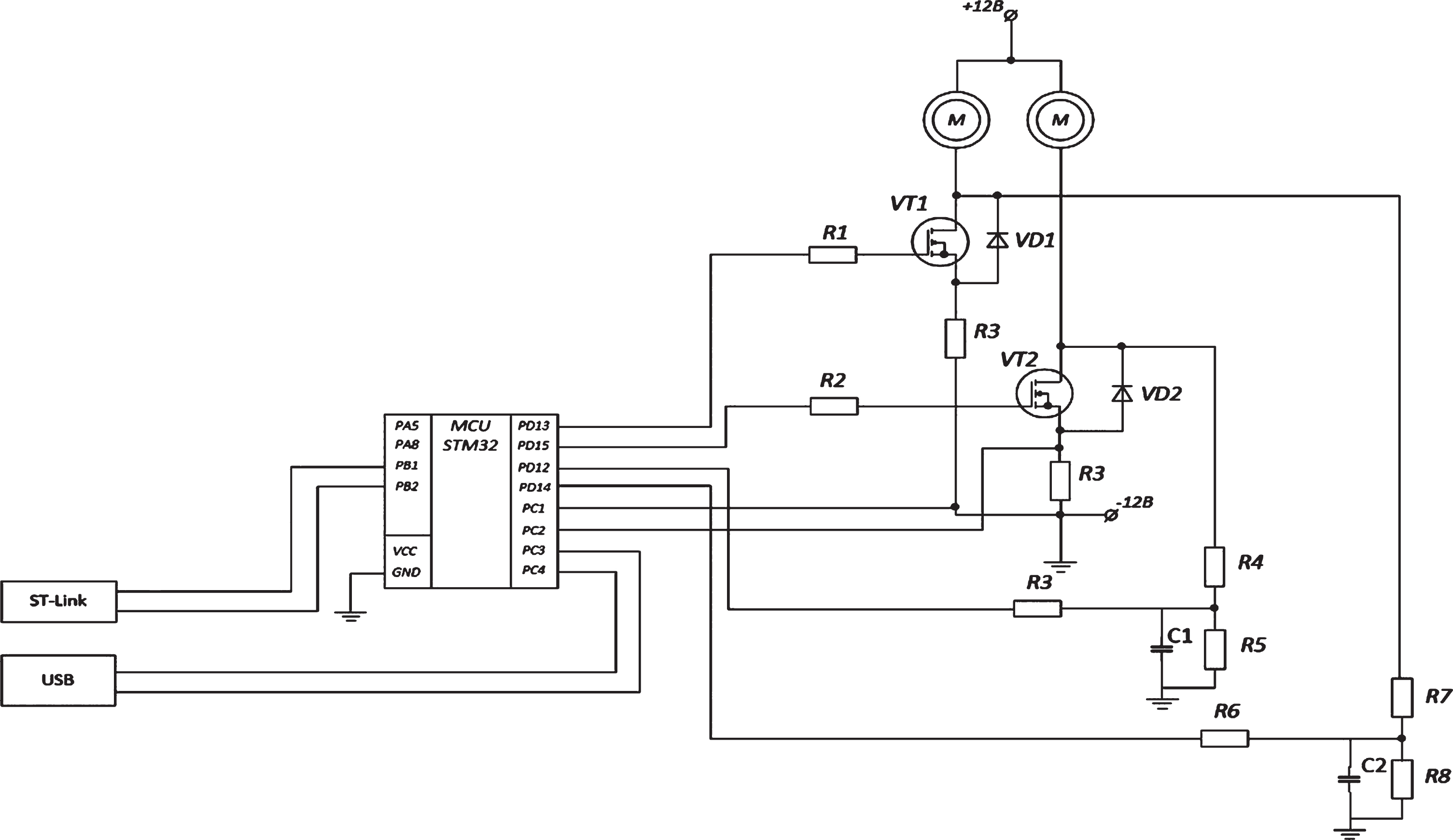
Driver for connecting pumps to the microcontroller.
The specialized algorithm of the system (Fig. 2) consists of the initialization cells of the controller and peripheral devices. Further, after polling the buttons, a control scheme is selected, i.e. manual and automatic. Both control circuits operate on a cycle of polling sensors and comparing them with actual parameters. After making a decision, the system sends control signals to the PWM control generation unit.
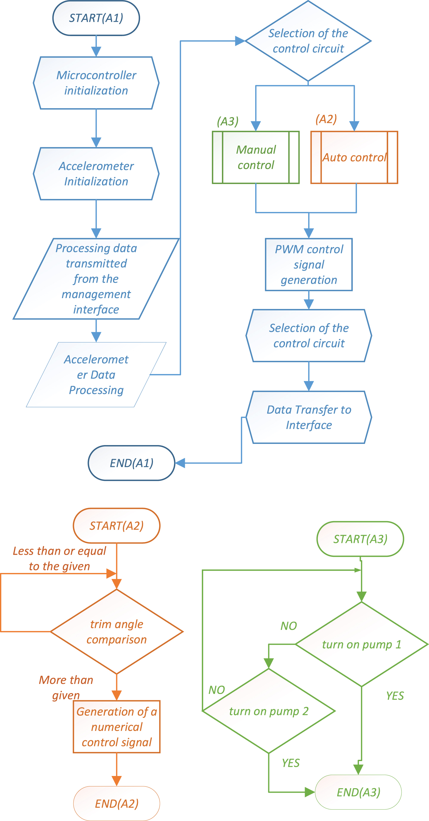
The algorithm of the automated list control system.
To work with the STM32F4 microcontroller and to code it, the mathematical modeling environment Matlab/Simulink is used with the addition of WaijungBlockset extension libraries.
Program of the lower level “SPI”.
Component blocks of logic elements and register addresses of the initialization block LIS3DSH.
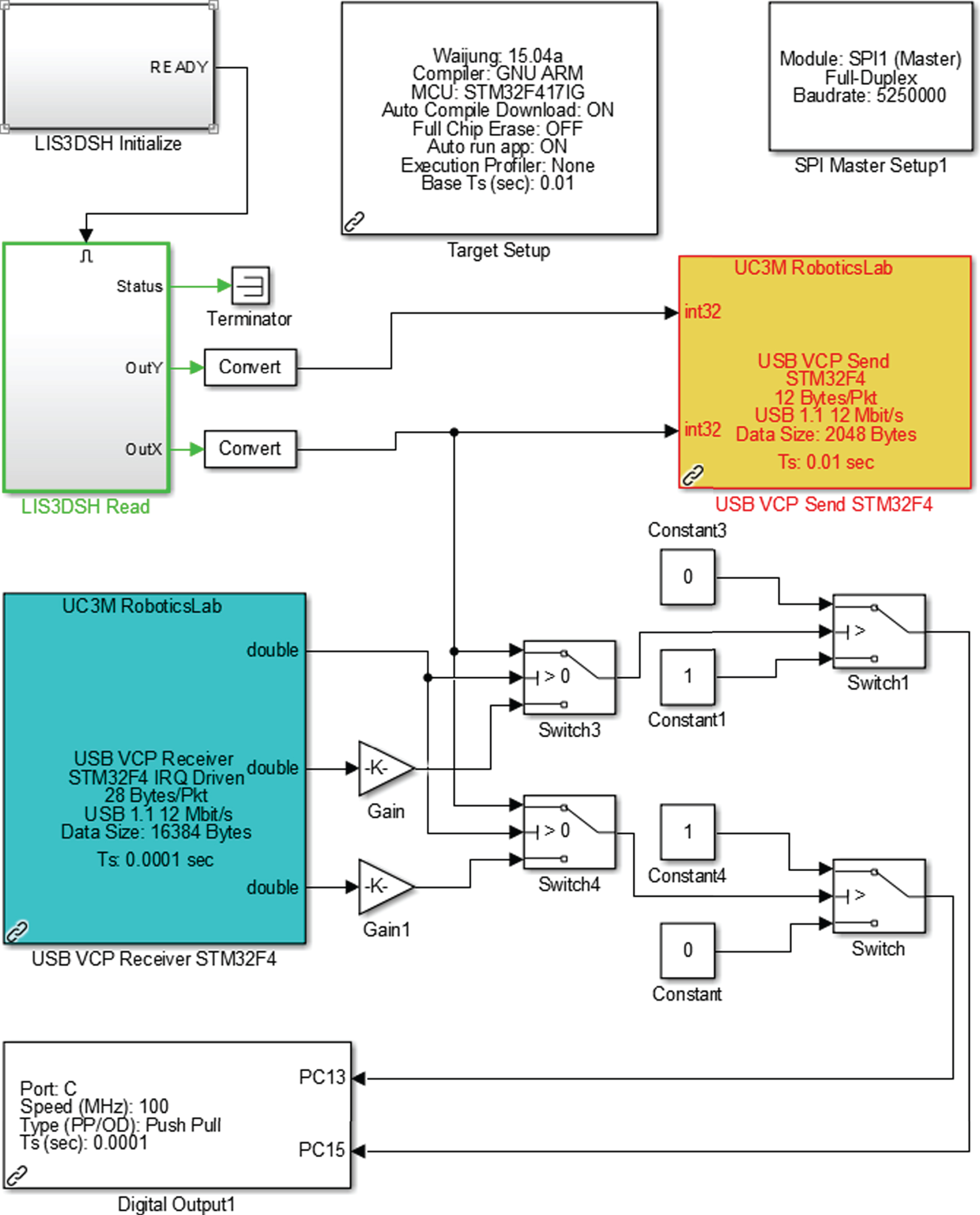
In order to interact and to make the data exchange by the microcontroller with a peripheral device (accelerometer) possible in the environment of Matlab and Simulink, the SPI MasterSetup block is used.
To initialize and configure the microprocessor, the TargetSetup block is used. This block selects the type of microcontroller used (Fig. 3). Also, this block generates a code for the selected MC and a cross-compiler type for compiling the generated code, selects the clock frequency and controls the process of code assembly starting from automatic compilation till loading [6].
WaijungBlockset has an integrated Multirate Single Tasking scheduler. This means that the base interrupt timer (based on the SysTick module) will be automatically set to the minimum system fetch time.
Initialization and interaction with the accelerometer is carried out on a register. To write and read registers, one needs to send the data address via the SPI bus of a specific format.
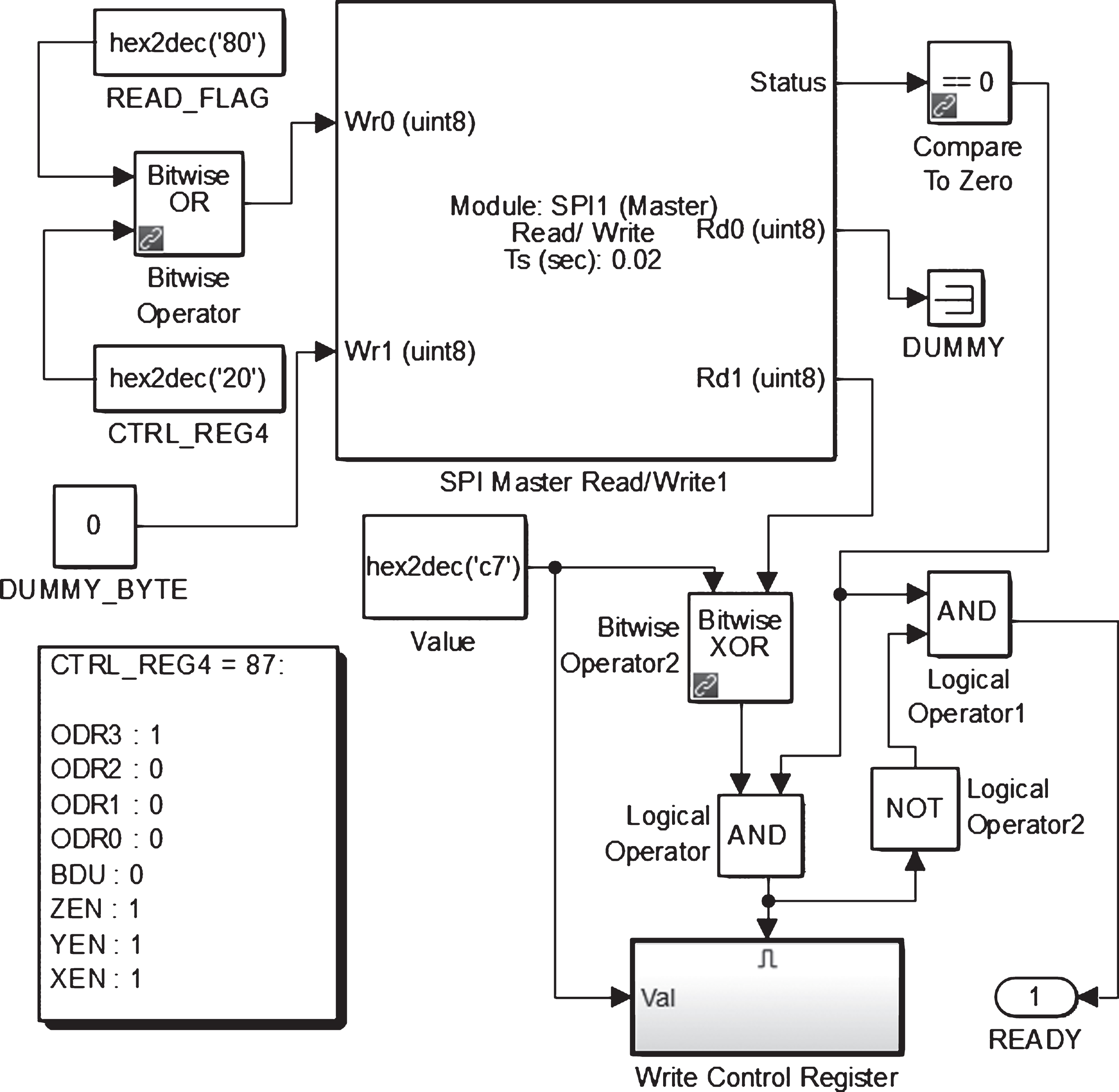
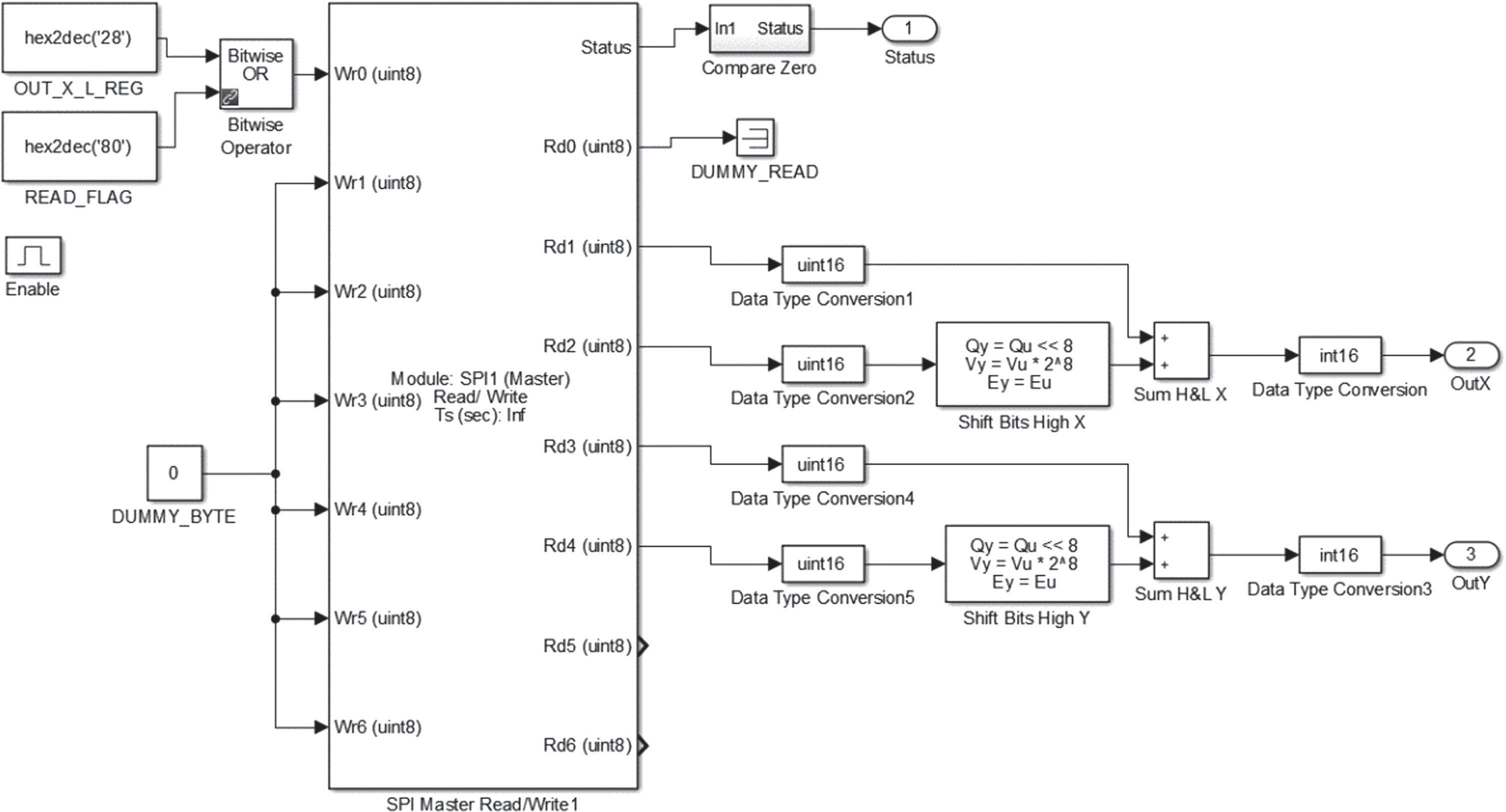
The initialization block consists of the following logic elements and register addresses for setting and checking the operation mode of the LIS3DSH accelerometer (Fig. 4).
In addition to the mechanism above, Waijung also automatically classifies tasks as critical in real time or not critical in real time (background tasks). Examples of real-time tasks are reading ADC inputs or generating DAC outputs. Examples of real-time non-critical tasks are symbolic LCD updates, CANBUS or other communication message processing as well as web server message processing. For critical tasks in real time, Waijung automatically generates and places the main functions for such tasks in the main (Systick) timer interrupt processing routines. Procedure of a non-real-time task provides a more flexible and practical application. For example, the system can be configured to work with a fast internal control loop (such as pulse width modulation control or capture input signals) as critical tasks in real time, while an LCD (non-real-time task) updated at 30 Hz; it works without blocking critical functions in real time. Provisions in the form of a subsystem for calling asynchronous interrupt functions become available if real-time responses are needed to be used with critical non-real-time tasks [7–12]. As Waijung is trying to determine the sampling time automatically, the “Diagram” needs to be updated twice. The first update is the determination of the sampling time of all units in the system, except for the target setting block. The second update should determine the base sampling time (sampling time of the target setting block) based on the information of the first update.
The register addresses are set by the READ_FLAG and CTRL_REG4 command blocks and are written to the microcontroller memory block using the SPIRead/Write protocol. First, 2 bytes of information are supplied: the first byte is the CTRL_REG4 register (control register that sets the frequency value, power control bit, measurement range selection bit, self-diagnosis control bit); the second byte is READ_FFLAG (status register).
The register CTRL_REG4 possesses the following parameters (Table 1):
Parameters of the register CTRL_REG4
Parameters of the register CTRL_REG4
ODR [3 : 0] is used to set the power supply mode and select ODR. Table X (data transfer rate selection) shows all available frequencies.The BDU bit is used to prohibit updating of output registers until both the upper and lower parts of the register are read. In the default mode (BDU=‘0’), the values of the output register are constantly updated. When the BDU is activated (BDU=‘1’), the contents of the output registers are not updated until both MSb and LSb are read, thus avoiding reading the values associated with different sampling times.
Since the CTRL_REG4 register transmits address data every 20 ms period, the register is alternated. This period of time for polling the sensor is required to convert the obtained angular acceleration into the angular velocity that we need. To write a value to the CTRL_REG4 register, the Value block is used with further bit parameters, which must be converted to a HEX value (Table 2). For the device developed, the value of the CTRL_REG4 register is C7.
Configuration of the parameter ODR in the register CTRL4
The BitwiseOR operator block skips writing to one of two registers. The READ_FLAG register transmits address data in a constant mode. Since the CTRL_REG4 register transmits address data every 20 ms, and then register writing is alternated. This period of time for scanning the sensor is required to convert the produced angular acceleration to angular velocity. The set of logic blocks on the right-hand side serves to check the operating modes of the LIS3DSH accelerometer and determine its state if there is 1 at the output of the READY block. This will mean that the device is ready for operation. Upon receipt of a positive generated signal from the initialization block, the LIS3DSHRead information scanning block is turned on. LIS3DSHRead according to the specified parameters of the generated signal, reads the accelerometer information along two axes X and Y, and also converts the value of angular acceleration into angular velocity (deg/s).
Figure 5 shows the visualization program for scanning the information and its transformation with further transfer to MC.
Information scanning program.
OUT_X_L_REG is an eight-bit register for recording acceleration data along the X, Y axes. Since the value of the angular velocity in a 16-bit number system, it is required to connect the desired value of the angular velocity from two 8-bit registers. On the right side of the program, it is converted to the desired format and then the specified parameters are converted from angular acceleration to angular velocity [7, 13–14].
Figure 6 shows the implementation program for launching actuators (pumps for pumping water from ballast tanks).
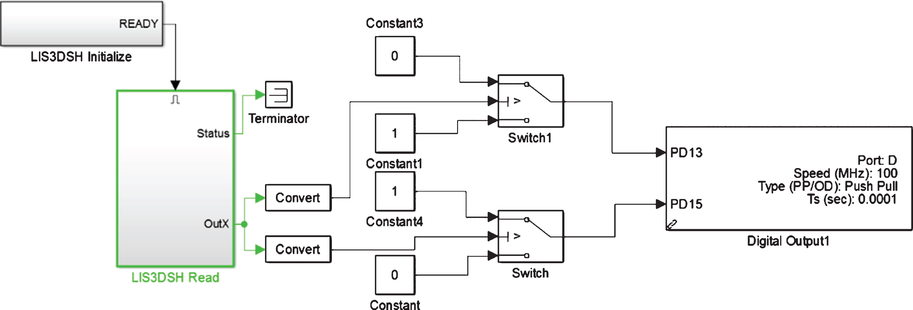
The program for implementation of the executive actuators starting.
The upper level program “HOST”.
The value of the angular velocity “X” when the board is rejected is converted and fed to the switching unit “Switch 1”. The switching unit “Switch 1” is configured so that if the numerical value of the angular velocity (X-) is greater than or equal to –1820 units. (10 degrees of deviation along the X axis), then a constant value “0” will be applied to the port of the digital output unit “PD13” (there is no power), as soon as this value becomes lower, a constant value “1” will be sent to the port “PD13” (there is power). “Switch0” works in a similar way, only to deviate to the other side (X+). The pumps are started using the digital output unit. This block implements the DigitalOutputModule (digital output module) for generating digital output logic from the pins of the microcontroller. The input port accepts any type of Simulink data. The microcontroller generates an output signal from the terminals based on the following logic: if (inputport = =1) OutputLogic1
else
OutputLogic0
End
The digital output unit is configured for every port separately. This means that every unit is used to configure the outputs of the specified port. To configure different outputs of the same or different ports, it is possible to have as many digital output units as required by the project.
To sample the information and its output to PC monitors, the USBVCPSendSTM32F4 block is used, which takes the values of the accelerometer and transfers them to the PC via the USB bus (Fig. 7).
To scan information further by the computer from the microcontroller using the Simulink medium, the HostSerialRx block is used. To send information from the computer to the microcontroller using the Simulink medium, the HostSerialRx block is used. Information from the accelerometer is scanned by the computer using the HostSerial Rx block and converted to degrees. On the X axis, the converted numerical values are output to numerical value monitors and a graphic monitor (Table 3).
Parameters of the register Host Serial Setup
Parameters of the register Host Serial Setup
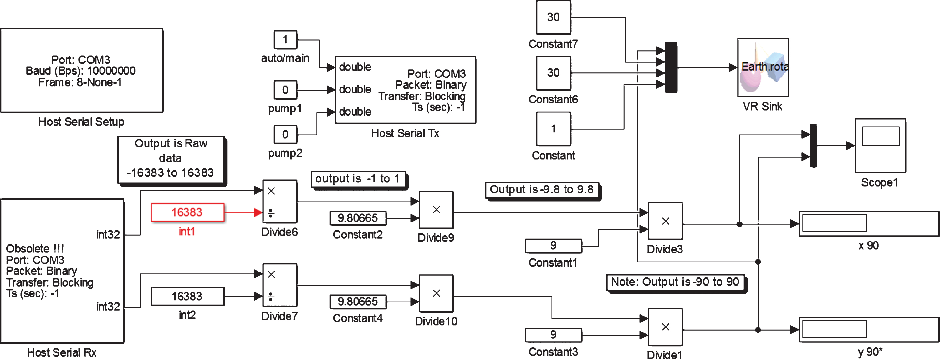
To implement the manual and automatic control for ballast pumps using a PC, a subsystem is implemented in the Simulink environment (Fig. 8).
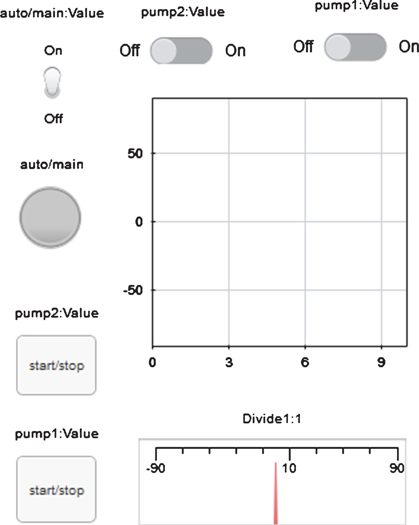
Subsystem for the manual and automated control.
The constant value “auto/main” controls the automatic or manual operation of the pumps and sends a signal to the “double” input of the HostSerialTx block. If the value is “1”, the computer sends a single signal to the “Switch 3 and 4” switches using the HostSerialTx block, they will remain in the open condition, and data coming from LIS3DSH will pass through “Switch 3 and 4”.
When changing the angle of inclination of the board with the microcontroller, the numerical values of the accelerometer will directly proportionally change from –16383 (–90 degrees) to 16383 (90 degrees). In the horizontal position, the value will be “0”, “Switch0” and “Switch1” will be in the open condition (as described above), the pumps will not be powered.
As soon as the MC changes position more than 1820 or less than –1820 (–10 /+10 degrees), then “Switch0” and “Switch1” will close and supply power to the pumps powered by “PD1” 5 and “PD13”. If one switches “auto/main” to the value “0” then “Switch3” and “Switch4” will close. In the closed condition, “Switch4” and “Switch3” will pass the numerical values coming from the PC via USB VCP.
For the experiments, the weight of the designed model was measured and the weight of the load was selected, the distances between the center of gravity and the point of applied mass were measured. The mass of the vessel is 4 kg, and the mass of cargoes are as follows: m1 = 355 g, m2 = 285 g, m3 = 175 g. The distance between the first point on the bow and the forecastle is 45 cm, and the second point is 23 cm. The length of the ship itself is 1.1 m. The maximum deviation during loading and the time of full compensation (Fig. 9).

The graph of the change in the angle of inclination over time and its full compensation.
On ships in operation, every opportunity should be used for trial verification of the position of the center of gravity and empty displacement of the vessel, taken in the stability calculations; in particular, such verification should be required when there is a reasonable doubt that the actual stability indicated in the stability poster is consistent.
The research results showed the correct operation of the model according to a specified algorithm. With a certain hull inclination designed by means of the applied load at a specific point on the deck (on the bow and forecastle), simulating loading operations in this way, all pumps begin to pump liquid ballast between the tanks in automatic mode as well as in the manual one if required. In accordance with the above program, which shifts the center of gravity to the desired position, the hull is aligned horizontally to compensate for the list of the vessel. To implement the alignment of the hull in the longitudinal vertical plane it is required to supply additional ballast by transfer pumps along the sides of the vessel. All the required data on the inclination of the vessel are displayed on monitors in the desired numerical format.
After repairs or installation of new pieces of ship devices and equipment on board the ship, tests should be performed, which are prescribed during their manufacture and installation on board the ship. Tests are carried out in accordance with the Guidance on technical inspection of the construction of ships and the manufacture of materials and products with the relevant paperwork.
When checking the stability of mixed navigation vessels, as well as non-specialized vessels used for the carriage of goods with a small specific loading volume, it is mandatory to check stability according to the acceleration criterion with the weather restrictions if necessary.
Stability calculations should be based on the experimental determination of the position of the center of gravity and the displacement of the vessel (heeling).
At the initial survey, the design features of the vessel, taken into account in the stability calculations, are subject to verification in relation to: openings in the end bulkheads of enclosed superstructures and in deckhouses, as well as openings on open decks and sides of the vessel; availability of the bilge keels; equipment of holds for the transport of bulk cargo; special devices for shifting the point of application of the towline tension on the tugs; the use of balancing pontoons in dredgers with a long-belt or conveyor method of the spoil ground removal; taking liquid ballast (if available).
The provision of stability is confirmed by the approval of the stability information for the master to be issued to every vessel. The information should consider the carriage of all types of cargo which the ship is designed for.
The physical model of the ship’s list control system was developed. It was concluded that the model was applicable for the study of problems associated with the automatic list control with modeling various loading options. Scalable loading studies of various types and sizes of cargo were carried out. Based on the study, a program for automatic roll control was developed. The results of the study showed that this control system was capable of securing the ship for various types of loading operations in the port, speeding up the loading process. It would thus reduce the time at the port and save port costs.