






Abstract
A combination of two optical elements: neutron guide followed by monochromator for neutron reflectometer was optimised. Several shapes of neutron guide were studied: classical, parabolic and elliptic ones. Flat or focusing monochromators considered. Guide coating and monochromator mosaicity were also varied. Calculations were made in the McStas package. The optimal combination for the maximum flux at the sample was found. For better performance an additional neutron guide after the monochromator is proposed.
Introduction
Recent years have shown the great advance in the neutron guides design: first ballistic [1,2], then more sophisticated parabolic [3,6] and elliptic guides [5,9] were developed. This progress was hugely motivated by the decision of construction of ESS. As a consequence a lot of attention was devoted to time-of-flight techniques, for example the problem of placing choppers on novel types of guides was discussed (see e.g. [4]). The general overview of different guide types performance was given in [7].
Meanwhile in Russia at the Petersburg Nuclear Physics Institute (PNPI) the construction of the high-flux PIK reactor in Gatchina has come to its final stage. A great number of instruments are planned for construction in the reactor (RH) and the neutron guide halls (NGH). Neutrons will be delivered to the NGH via an extensive guide system. Several instruments in the NGH will be of the crystal monochromator type. The aim of this article is how to choose the optimal neutron guide and monochromator for such an instrument.
The usual configuration is a guide with a constant rectangular cross-section with top and bottom walls coated with m higher than side walls. It is then followed by a vertically focusing monochromator. We take this case as a basic case and propose two alternatives. A second possibility is to build an expanding divergent guide (in our case of parabolic shape) that brings a well-collimated beam of large cross-section to the monochromator which focuses the beam on the sample. The third combination is a ballistic guide, namely of elliptical shape, with a focusing monochromator either in front or behind the elliptical focal point so it could additionally focus or refocus the neutron beam on the sample.
These three variants (see Fig. 1(a)–(c)) are discussed below in general and in particularly for the reflectometer NeRo [10]. This instrument was transferred from Helmholtz Zentrum Geesthacht, Germany to PNPI and now undergoes significant reconstruction to be installed at PIK.
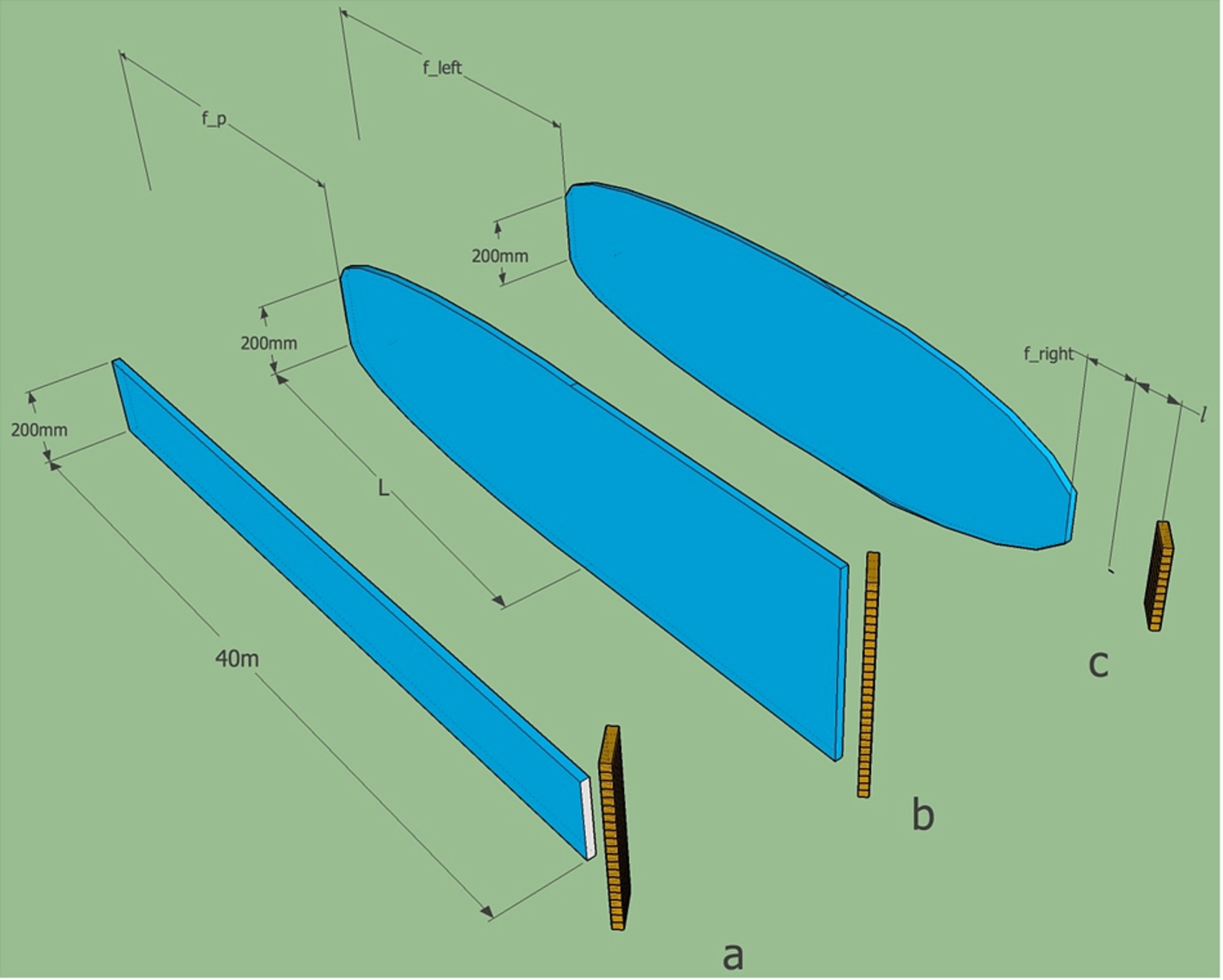
Three different configurations of neutron guide and monochromator considered for optimisations: a – straight guide; b – expanding guide of parabolic shape; c – ballistic guide of elliptic shape.
The part of the instrument to be simulated is presented in Fig. 2 (see also Fig. 1). The NeRo reflectometer guide is planned to be installed at horizontal experimental channel (HEC)-3. This beam tube views the cold source which has a spherical shape with diameter of 436 mm and is filled with deutirium. Beamtube length is 1.645 m, its height and width are 250 mm and 120 mm respectively. The exit window has a height of 200 mm, and a width of 320 mm. The source spectrum was described by three Maxwellians with
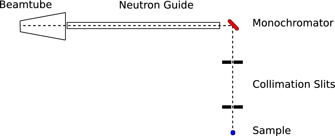
The schematic layout (top view) of reflectometer NERO part from source to the sample. Dashed line indicates the neutron beam.
Based on the planned position of NeRo in the neutron guide hall guide length was put to
For the monochromator we have used pyrolytic graphite with (0 0 2) reflection, which corresponds to interplanar spacing
The height of the sample was taken to be 1 cm based on a standard reflectometer sample size. Monochromator–sample distance was
The figure of merit for all simulations was flux through the sample with collimation slits in. All simulations were performed using McStas package [8,11].
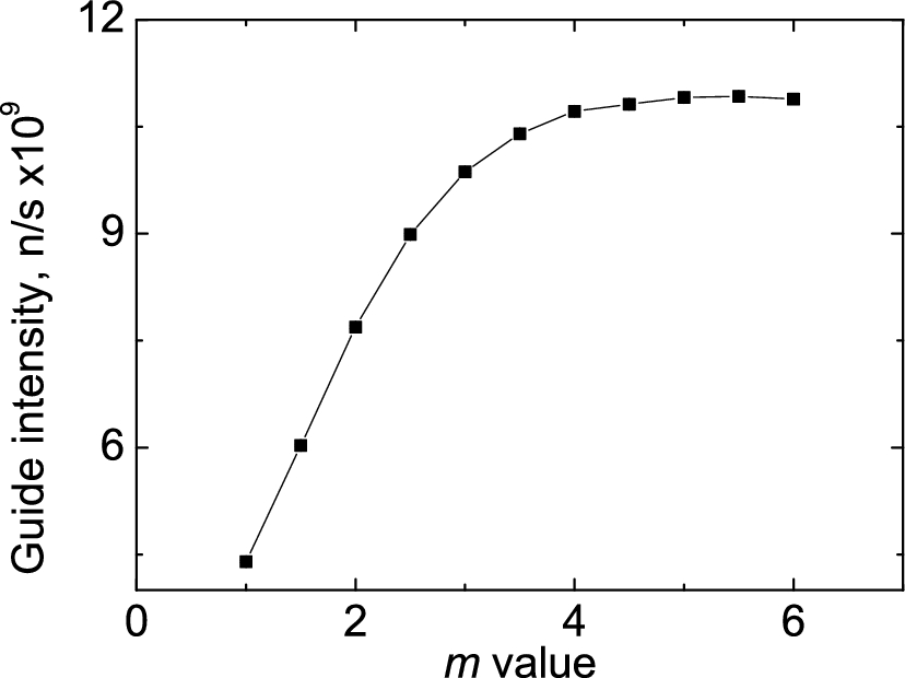
The intensity at the straight guide exit depending on the top and the bottom walls coating.
We first consider a straight guide with constant rectangular cross-section. Figure 3 shows the dependence of the flux versus critical angles of the top and the bottom walls. It indicates how the flux increases when m values increase up to
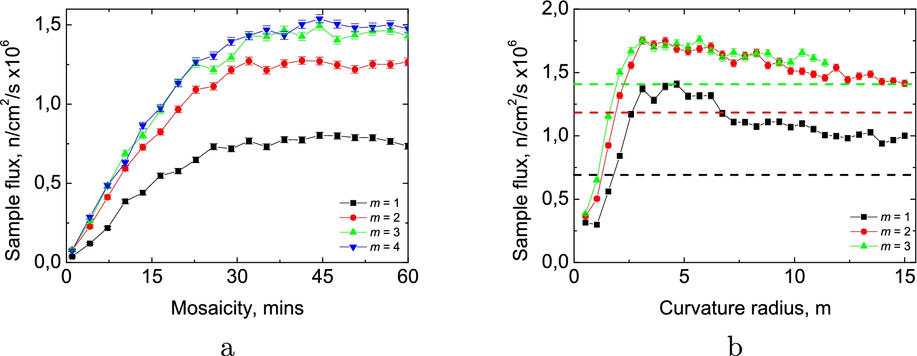
Flux at the sample position for the straight guide case: (a) for different monochromator mosaicity; (b) for different monochromator curvature. Dashed lines stand for sample flux with flat monochromator.
Finally we vary the optimal monochromator focusing condition. Results are presented in Fig. 4(b). The largest relative gain from curving the monochromator can be found for
Following this method we have found optimal parameters: guide coating
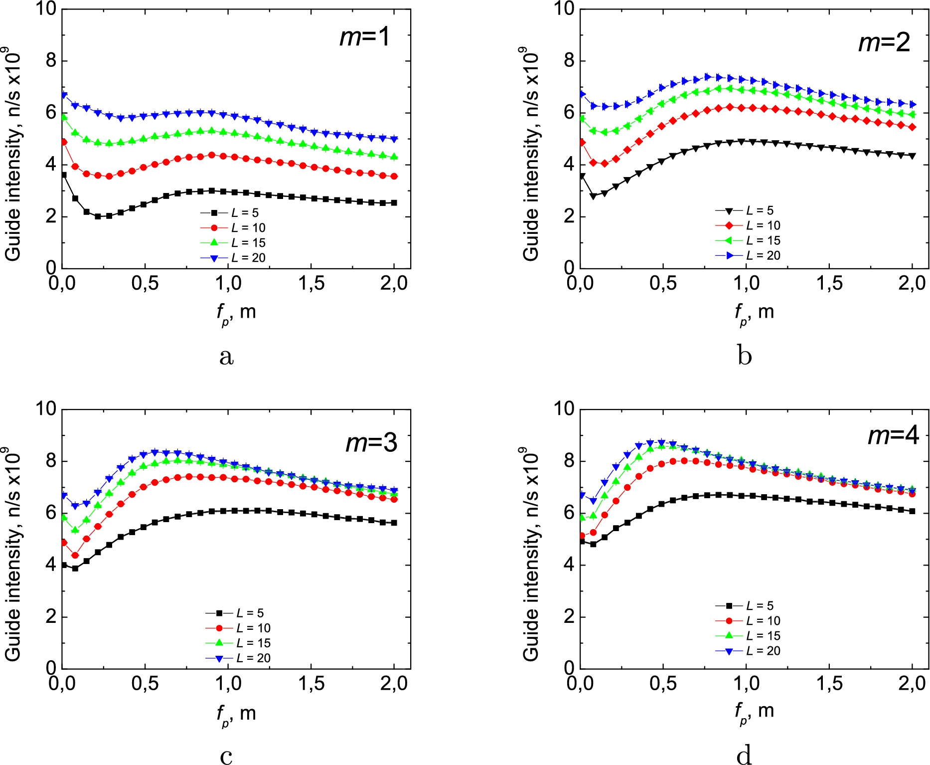
Flux at the expanding guide exit for different straight guide coatings (m = 1–4 at (a)–(d) respectively) and different expanding section length L in meters.
Given the fact, that a well-collimated beam is better suited for focusing we decided to use an expanding section in the beginning of the guide to get a large cross-section low divergent beam at the monochromator position. We have chosen a parabolic shape for that expanding part with a coating
First we take a look at the flux at the guide exit. The results are presented in Fig. 5. Based on these plots we can define the focal point position for each geometrical configuration (see Table 1). Increasing the expanding part length, L, and straight part coating, m, leads to an increase of the flux, but again the difference in overall flux between
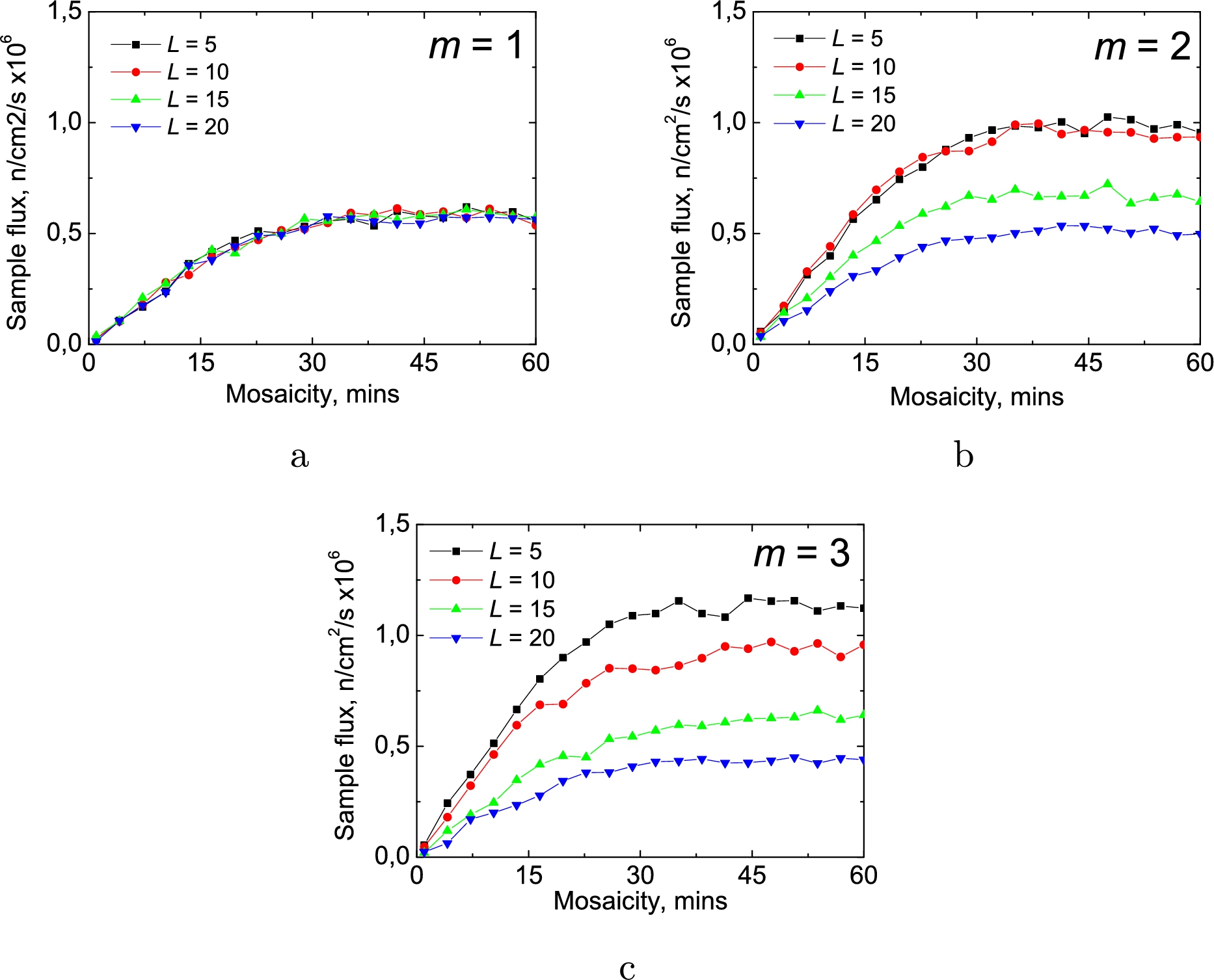
Flux at the sample position using flat monochromator for expanding guide case. (a), (b), (c) stand for straight guide coating m = 1, 2, 3 respectively.
Figure 6 shows the flux at the sample position versus mosaicity of the flat monochromator, which is placed at the end of the guide. Mosaicity dependences show similar behaviour to that for the straight guide case (see Fig. 4(a)). For a nickel coating all curves are the same, while for higher m value a short expanding section is preferable. This is due to the fact that a long expanding section leads to low divergent beam which is well transported by a nickel-coated guide. Shorter sections perform not so well and need higher m. The overall gain for shorter sections is due to flat monochromator nature: it needs higher brilliance, not total flux, while with an expanded guide one gets a low flux density.
The focal distance
Having found the mosaicity and focal point positions we consider a curved monochromator configuration, which was expected to have the best performance. Results are presented in Fig. 7. Focusing increases significantly the flux at the sample (up to
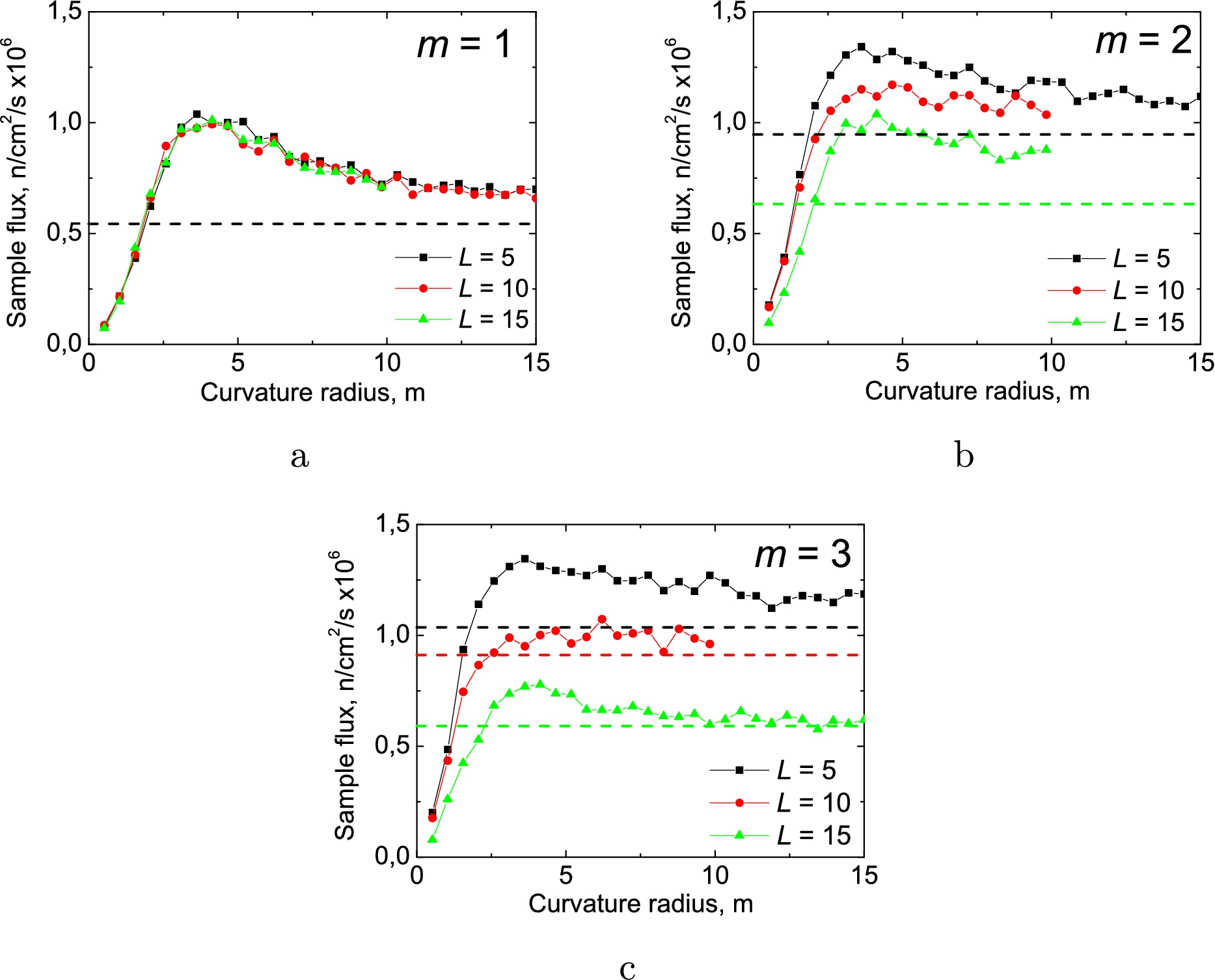
Flux at the sample position using a curved monochromator for the expanding guide case. (a) to (c) stand for straight guide coating
To verify the step-by-step optimization process we once again performed simplex optimisation with all variables set free. We discovered that the focal position tends to be as far away from guide entry as possible and expanding guide length tends to be minimal. That means that the whole configuration tends to become similar to the one with the straight guide described above.
Let us now consider the third configuration to transport high vertical divergence to the sample position. We use an elliptic guide, which has a higher acceptance angle viewing the source and forms a virtual source before the monochromator, which in turn refocuses beam onto the sample. Here the variable parameters are: distance from guide entry and exit to the left and right foci respectively; monochromator position relative to the right focal point; and its mosaicity and curvature radius.
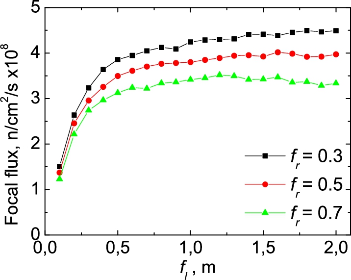
Flux density at the guide exit for ballistic guide case.
Figure 8 shows the optimisation of an elliptic guide geometry. Note we measure here not total flux at the guide exit as for other cases but flux through 1 cm2 to find the optimal focal distance. The best solution is to use a larger left focal distance
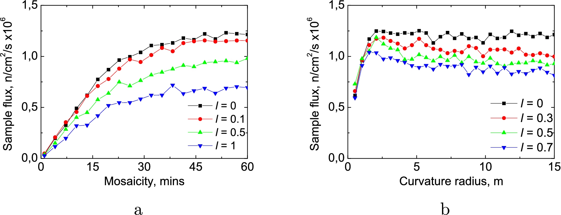
Flux at the sample position for ballistic guide case: (a) for different monochromator mosaicity; (b) for different monochromator curvature.
The free simplex optimisation leads to very large values of both focal distances
Figure 10 shows a horizontally integrated beam cross-section at the sample position for different guide configurations. Blue lines indicate the sample height. As one can see from this picture the total flux from a ballistic guide gives factor 0.35 of the total flux from the straight one, while expanding parabolic guide provides 1.79 larger flux than the straight one. If we take into account the sample size we get different ratio for these three cases, but in any case both alternative configurations are inferior to the standard one (straight guide with focusing monochromator) and provide only factor 0.7 of the flux of that one.
While for the TOF reflectometers the task of increasing the sample flux can easily be accomplished by transporting high divergence from source, for the case of crystal monochromator instrument it is not so straightforward. The monochromator effectively puts a limit to the largest possible useful divergence. For example (see Fig. 8) the elliptic guide allows to transport much more neutrons than the straight one, but these neutrons can not be reflected by monochromator to the sample position. The important parameters occur to be both the monochromator sample distance and the sample size. Their combination defines the accepted useful divergence, which in our case is perfectly transported by the straight guide.

Vertical beam cross-section at sample position for different guide configurations.
Figure 10 also shows that for all cases a lot of neutrons miss the sample. To improve the situation it seems useful to introduce a focusing guide section between the monochromator and the sample converging in the vertical direction. Figure 11 shows possible gains using such a device with maximum of 2.25 times relative to the no-guide case. About 71% of all reflected neutrons are transported to the sample position (ones with highest divergence are absorbed), which means that application of a more sophisticated guide shape here would in principle give an additional 40% gain. At the same time it should be noted that construction of such a guide could encounter technical restrictions due to monochromator shielding, precise positioning inside of vacuum vessel, interaction between guide and flipper etc.
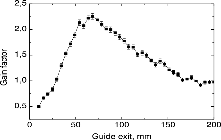
Gain factor due to using focusing guide for different guide exit heights.
We have discussed three possible configurations of neutron guides for a monochromatic beam reflectometer: using a straight guide (standard), a parabolically expanding or a ballistic of elliptical shape. The standard one shows the best performance, while parabolically expanding could be advantageous for very large samples (more than 8 cm high, see Fig. 10).
We note that it is crucial to optimise the guide and monochromator together and with respect to the sample size.
We have also shown that a large gain in flux of at least 2.25 could be achieved using a focusing section between the monochromator and the sample. We assume that building such a device is the most practical way to upgrade monochromatic reflectometers in future.
Footnotes
Acknowledgements
The authors wish to thank Dr. N. Pleshanov and Dr. V. Syromyatnikov for useful discussions. The work was partly funded by a grant from Ministry of Education and Science of Russian Federation number 14.616.21.0004.