
Abstract
With a nominal beam power of nearly 1.4 MW, the PSI High Intensity Proton Accelerator (HIPA) is currently at the forefront of the high intensity frontier of particle accelerators. Key issues of this facility are minimization of beam losses as well as safe operation of the SINQ spallation source. Particular attention is being recently paid towards an improved understanding of the properties of the SINQ beam line by both enhancing the beam transport simulations and developing new diagnostic elements which can also, in some cases, preserve the target integrity by preventing too large beam current density, inaccurate beam steering or improper beam delivery. Moreover, part of the SINQ beam diagnostic concept is being rethought in order to include important missing devices like BPMs. On the simulation side, newly developed composite calculations involving general purpose particle transport programs like MCNPX and BDSIM will deliver insights about beam losses and transmission through collimators. All recent and planned developments of the SINQ beam line will be discussed in this contribution.
Introduction
The PSI High Intensity Proton Accelerator (HIPA) generates a continuous wave beam with a maximum power of 1.4 MW. Protons are brought to 590 MeV energy by an accelerator chain consisting of a Cockcroft–Walton generator followed by an injector and a ring cyclotron [10,14]. After extraction, the beam is delivered to four different target stations, two meson production targets and two spallation sources. The 590 MeV proton channel and the secondary beam lines are displayed in Fig. 1. The beam is transported through a 60 m long beam line provided with two graphite target stations, so-called TM and TE and installed 18 m apart from each other. TM has a thickness of 5 mm and absorbs ~1% of the beam. TE is 40 mm (alternatively 60 mm) thick and absorbs ~8% (~12%) of protons. The highly divergent 570 MeV (560 MeV) beam leaving TE is reshaped by a system of four copper collimators and delivered to the SINQ spallation source. A total fraction of protons in excess of 20% (30%) is stopped by the collimators or by the local shielding while ~70% (~57%) of protons are transmitted to the SINQ target through a 55 m long beam line. The SINQ target consists of a 40 cm deep vessel containing over 300 zircaloy tubes filled with lead rods and cooled by heavy water. Should the SINQ facility undergo a technical stop, the meson production targets can still be operated. In this case, after scattering off TE the beam is absorbed by a dump designed for a maximum power of about 700 kW.
In 2011 the ultra cold neutron source (UCN) was brought into routine operation [1]. This second spallation source runs concurrently to SINQ and is driven by the full power beam thanks to a fast kicker magnet located some 15 m downstream of the extraction point and capable of diverting the proton beam into the UCN line within 1 ms time. UCN macro-pulses with length up to of 8 s occur every 300 s, with a maximum allowed duty-cycle of 3% (at 2.0 mA proton beam current).
During the 44 years of operation, the beam current of the PSI proton accelerator has been growing from 0.1 to 2.4 mA. At the maximum beam intensity and when the 40 mm TE is in operation almost 1 MW power is dumped into the SINQ target. Under such conditions, a sudden change of the beam optics and/or position can easily lead to excessive thermomechanical stress of the spallation target. The investigations carried out after the damage suffered by SINQ target 11 in June 2016 pointed to an undetected missteered and overfocused beam which could have potentially triggered the occurrence. In order to avoid such events in the future, a campaign has been launched aiming to increase the target safety by improving the beam diagnostics. At the same time, new light is being shed in the understanding of the beam loss processes through targets and collimators thanks to the employment of software tools like MCNPX in addition to the traditionally used Turtle particle tracking code [12]. After a detailed description of the SINQ beam line, the following sections will present the progresses made so far in both aspects.
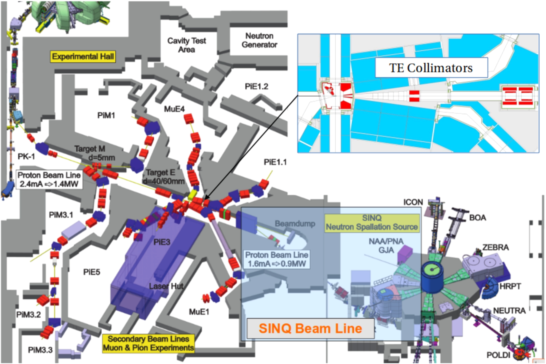
Drawing of the PSI-HIPA 590 MeV proton channel along with the two meson production targets TM and TE as well as the SINQ spallation source. A detailed view of the TE region with graphite target, wheel, the local shielding and the four copper collimators in red colour is depicted in top right corner.
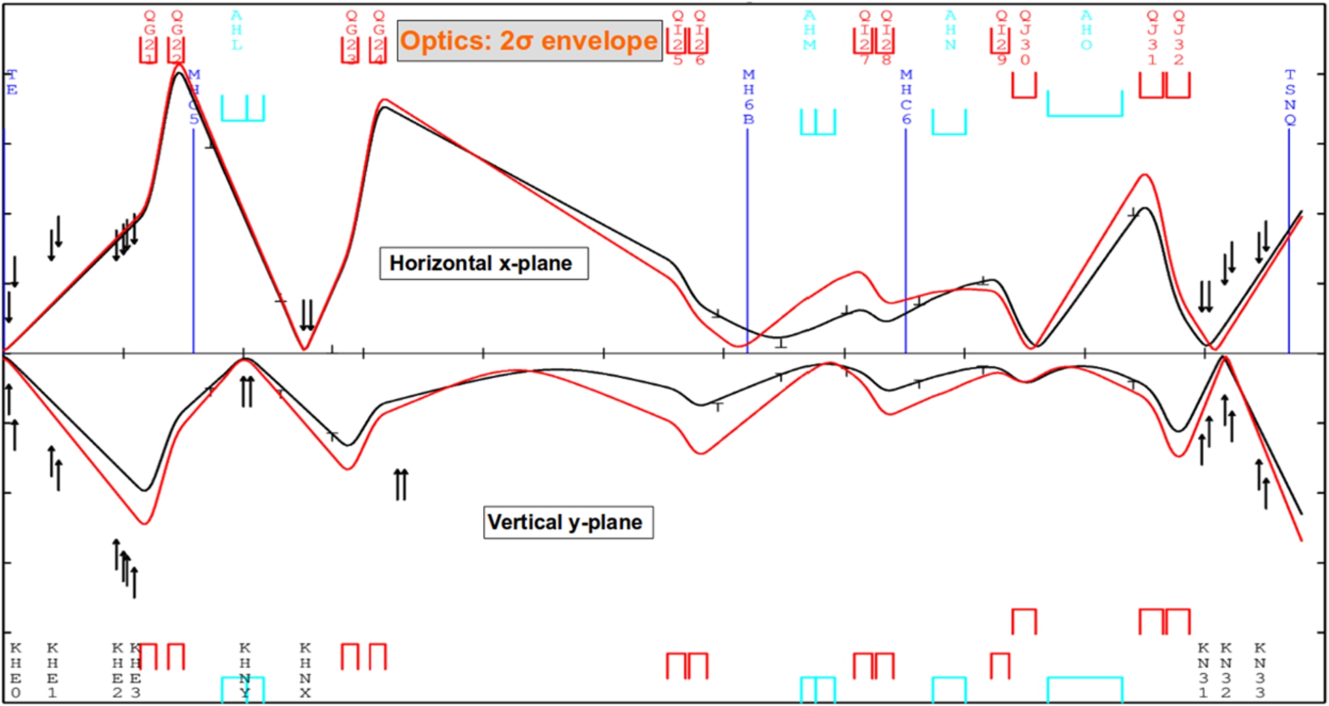
Beam envelope fit between TE and SINQ for TE40 (black) and TE60 (red). The T-shaped marks represent the 2σ widths of the Gaussian fit of beam profiles measured when TE40 was in operation.
Figure 2 shows 2σ envelope fits of the proton beam along the 55 m beam line between TE and the SINQ target (TSNQ) in case of a 40 (black) as well as 60 mm (red) thick target (TE40 and TE60 in the following). The fit constraints are given by the beam widths measured by the profile monitors. The half aperture in both horizontal (upper) and vertical planes is 150 mm. The quadrupole magnets are depicted by the red rectangles. The location of the TE copper collimators (KHE0-3), the vertical and horizontal scrapers (KHNY-X) as well as the three copper collimators protecting the SINQ target (KHN31-33) are displayed by black arrows.
After passing through TE and the collimator system, the beam gets cut short in the horizontal plane (upper envelopes) by KHE2-3. Downstream of the first doublet, the beam is diverted downwards and then upwards by means of four dipole magnets (light blue rectangles) before being vertically dumped into the SINQ target. In the region between the last doublet and the SINQ target the beam optics has to follow the rather complicated shape of the KHN31-33 collimators.
During its design phase (some twenty-five years ago), the beam line between TE and SINQ was furnished with the following diagnostic tools:
13 beam loss monitors (MHI21-24 and MHI31-39); 2 second harmonic resonator beam current monitors (MHC5-6) [5]; 8 aperture monitors located at the upstream end of collimators or slits and made out of thin nickel foils (MHB5-6, MHB21-22, MHB31-34); 18 wire scanner beam profile monitors (MHP41-58).
Beam position monitors were not foreseen by the beam line designers and, for this reason, since then and to date are not present in the SINQ beam line. However, BPMs are installed in the section between the ring and TE. Together with the steering magnets, they are part of the beam centring loop which keeps a stable beam position within 0.1 mm tolerance on both meson production targets TM and TE.
A challenging issue is the potential missteering of the 590 MeV beam, which could cause a fraction of protons to miss the 6 mm wide TE graphite wheel. Due to the large momentum acceptance of the SINQ beam line, this unscattered full energy protons would reach the SINQ target. Since its relative current density is about 20 times larger compared to the beam going through TE, even small amounts of TE-bypassing beam must be detected within a time range of few tens of ms in order to allow for a beam interlock before a damage in the SINQ target occurs. Since the very beginning of SINQ, the standard method to detect the TE-bypassing beam and interlock the machine before a damage to the spallation target occurs is to monitor the beam transmission through TE by comparing the proton current measured by two devices located respectively down- and upstream of TE. The capability of this method to effectively detect proton side-wise by-passing TE has been significantly limited since 2001, when the TE-wheel was provided with 12 slits allowing for thermal expansion. Since TE rotates at 60 rpm (1 Hz), the slits produce a 12 Hz modulation of the beam current with a 3% amplitude variation. As a consequence, only a transmission increase of at last 3.5% can be interpreted as TE-bypassing beam and trigger therefore a beam interlock. Such an amount of TE by-passing beam is already potentially dangerous for the integrity of the SINQ target.
For the MegaPie experiment carried out in SINQ in 2006, two additional safety devices have been conceived and installed. The first is the VIMOS [15], a glowing tungsten mesh based visual monitor located 40 cm upstream of the SINQ target and providing qualitative information about the beam footprint on target. The latter, the KHNY30 slit, consists of a pair of vertically movable copper jaws and located in the high dispersion region inside the quadrupole magnet QHJ30 [13]. Thanks to the particle shower produced by the interaction of the TE-bypassing beam with the lower copper jaw and detected by the beam loss monitors, this system can spot fractions of beam bypassing TE in the order of 1% of the full intensity. Unfortunately the reliable operation of this system can not be guaranteed. The 30 cm long uncooled massive copper blocks of KHNY30 would in fact need a constantly centred beam in order not to overheat and generate massive beam losses with consequent beam line activation. This condition can not be fulfilled due to the absence of BPMs.
The lack of BPMs prevents also the implementation of an automated beam trajectory correction which would stabilize the beam position on the SINQ target. Moreover, the frequent tuning of the injector and the ring cyclotron by the operators has an impact on the quality of the extracted beam and can generate beam position instabilities with consequences on the beam loss level. The proton channel centring loop compensates for any change of the beam parameters, but only up to the last BPM, located around 4 m upstream of TE. The 60 m path between this point and the SINQ target is too long to avoid that even tiny beam displacements propagate into rough misalignment. Moreover, the last four meters of beam line upstream of TE host an horizontal magnetic bump which bends the TE-backscattered muons into one of the secondary beam lines. Any change of the bump setting has an effect on the proton beam position and/or angle on TE and therefore, on the beam centring in the SINQ beam line. Substantial deterioration of the beam losses is usually due to the fact that, if misplaced, the beam hits the scrapers KHNY-X asymmetrically, hence generating a larger amount of halo which might deposit onto the following beam line elements.
All these issues make the setting of the SINQ beam line a tricky task that has to take into account different and sometimes contradictory constrains like loss optimization and target safety. During beam operation, the beam line must be periodically checked and optimized by measuring beam positions and performing envelope reconstruction by means of the profile monitors. In order to make the beam line more user friendly and try at the same time to prevent any bad occurrence which could damage the SINQ target, a campaign has been recently launched aiming to improve the beam instrumentation. At the same time, it has become clear that the commonly used Transport/Turtle [12] simulation tools could not account for all beam loss mechanisms hence suggesting the employment of more sophisticated codes like MCNP/MCNPX [9], which could provide deeper insight into beam properties and loss distribution. These necessary steps towards improved beam line instrumentation and simulations have been strongly triggered by the failure of SINQ target number 11 occurred in 2016, when an unintentional beam hot spot likely broke one of the lead filled Zircaloy tube which caused a partial blockage of target water cooling loop [8] leading to an unscheduled four-month shutdown of the facility.
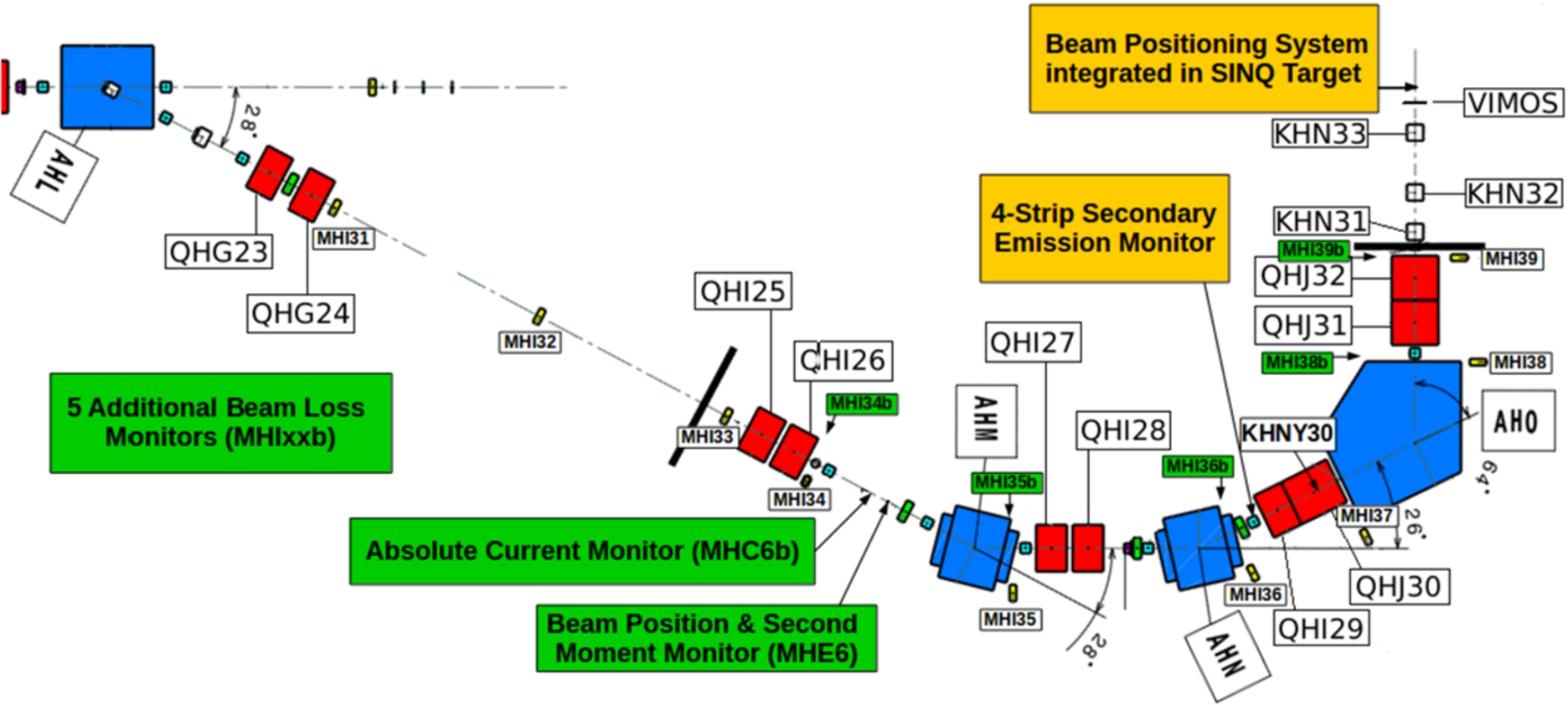
Drawing of the ~50 m long vertical portion of the SINQ beam line. The beam is diverted downwards by the AHL bending magnet and finally bent upright by AHO before impinging on the SINQ target. New diagnostic elements installed in 2017(2018) are described in the green(yellow) boxes.
During the HIPA shut down periods 2017 and 2018 the SINQ beam line was equipped with a number of new monitors (Fig. 3) aiming to simplify the beam tuning and increasing at the same time the SINQ target safety. Moreover, during the 2019 running period, a TE prototype provided with beam centring grooves was tested which delivered very promising results.
Additional beam loss monitors (BLM)
The last six out of the nine original BLMs (MHI31-39) are installed on the bottom side of the beam line. Due to the momentum dispersion introduced by the AHL dipole, the distribution of the low energy tail of protons scattered off TE results in a top/bottom asymmetry. In the downstream part of the beam line (starting from the quad QHI25), losses due to this tail will affect differently the upper and the lower side of the beam line up to the point where the dispersion is canceled by the AHO dipole. In order to try to assess this asymmetry, five additional BLMs were installed on the top side of the beam line, three of them in the non zero dispersion region (MHI34b, MHI35b, MHI36b) and two in the dispersion free region (MHI38b and MHI39b). The signals delivered by the additional BLMs proved to be very helpful for beam line optimization as well as for additional interlock triggers to constrain the beam losses during operation.
Absolute current monitor
The fast measurement of the beam current in the SINQ beam line plays a crucial role for the detection of unexpected losses [5]. This task is taken over by two 2nd harmonic resonators, MHC5, installed in the highly activated region downstream of TE, and MHC6, located some 25 m downstream. Although very fast, these monitors can only measure relative beam currents and must be calibrated by means of the absolute current measurement provided by a Bergoz® [16] monitor (MHC2b) located upstream of the first graphite target TM. This value has to be multiplied by the beam transmission through targets and collimators before reaching MHC5 or MHC6. The knowledge of the beam transmission comes from beam line simulations performed by means of the Turtle software tool. The critical point here is that the transmission rate is not fixed, since small changes in the beam divergence upstream of TE reflect in a variation of the amount of beam absorbed by the TE collimators [11]. Tests have shown that the beam transmission can vary by over 2% by slightly changing the quadrupole setting in the TM-TE beam line section. For this reason, a precise determination of the beam transmission cannot be performed without the help of a second DC current monitor. This device, called MHC6b, was installed in the SINQ beam line during the 2017 HIPA shut down and commissioned during the following run (Fig. 4). The Bergoz® turns out to be very useful also for correcting any MHC5 or MHC6 resonator beam current monitor calibration drift. Indeed, the temperature changes experienced by the resonators modify the resonance frequency, leading to a calibration drift.
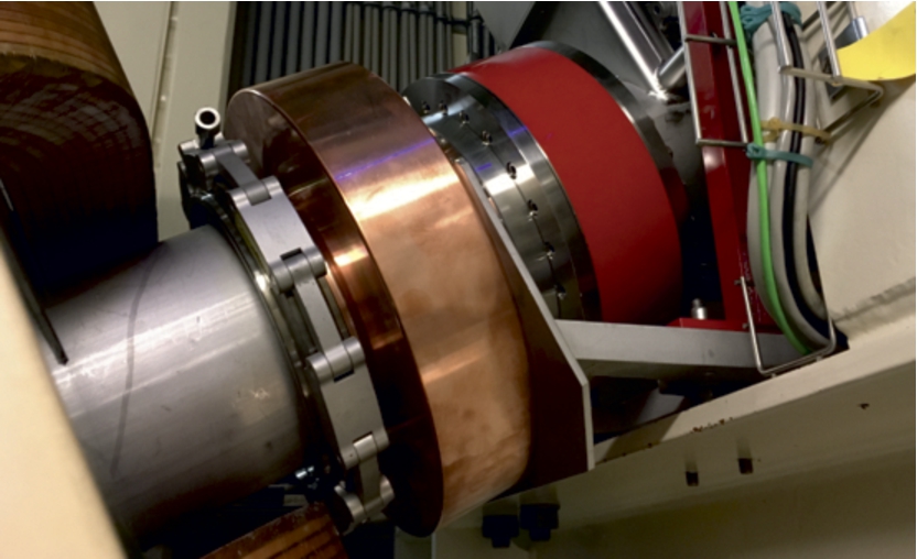
The Bergoz® absolute current monitor (right) and the beam position and second moment monitor (left) installed in 2017 in the SINQ beam line. The beam comes from the right.
Concurrently with and next to the Bergoz®, a beam position and second moment monitor (BHE6) was installed in 2017. This monitor consists of 8 wide-band magnetic pickup coils and can measure the moments
Layout of 4-strip secondary emission monitor. Signals from the four strips (cyan, blue) are read out individually. 2σ beam contours are indicated for regular (full red) and irregular (dotted red) beam.
The KHNY30 vertical slit is supposed to detect TE-bypassing beam. Yet finding a reliable working point for its massive and uncooled jaws without an automated beam trajectory correction proved to be very hard. This issue was overcome with the design of the 4-strip secondary emission monitor MHB28 (Fig. 5).This device was installed slightly upstream of KHN30 and commissioned during the 2018 run. By limiting the signal currents allowed at the close inner strips, the main beam is forced to be centred vertically. Being made by 20 μm Molybdenum foil strips, this device, contrary to KHNY30, does not overheat or produce any sizable beam loss (according to Turtle simulations). In the ideal condition of centred beam, the signal currents at the outer strips result from less than 0.1% of the regular beam. Even a small fraction of approximately 1% of beam missing TE clearly increases the signal at the outer lower strip, which is used to trigger a beam interlock. The relative difference of the signal currents at the inner strips provides the information for vertical beam centring. This monitor is discussed in detail in [4].
SINQ beam positioning system
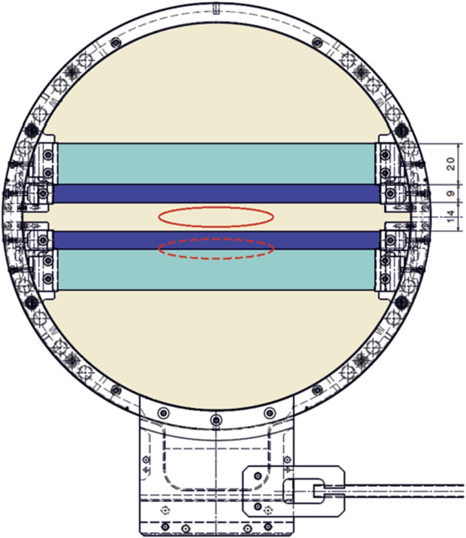
Several SINQ targets employed during the past runs have been equipped with a number of temperature sensors providing important information about the beam setting. The experience collected so far has allowed the development of a temperature based Target Beam Positioning System (TBPS) shown in Fig. 6. This tool is available on the SINQ target 13 employed during the 2018 run and to be used again in 2020 (in 2019 SINQ underwent an extended shutdown due to the neutron guides upgrade project [7]). It consists of four temperature sensors attached to the target rim and positioned along the elliptical edge of the beam footprint. Two additional temperature sensors located in the centre of the SINQ target and installed in two different zircaloy rods (rows 12 and 14 respectively) measure the temperature in the region of maximum energy deposition. At any given beam current and in case of a perfectly centred beam, the four sensors measure similar temperature values and both sensors located in the target reach a local maximum. Beam intensity dependent temperature curves have been determined by performing several beam current scans. Any deviation from the ideal case can point to a beam misplacement, over- or defocusing. An algorithm to calculate the beam position starting from these parameters is under study and should be applied during the next run in 2020. All the information coming from the TBPS is available in the HIPA control room and displayed in a GUI (see Fig. 6). In the future, these signals could be used by the machine interlock system.
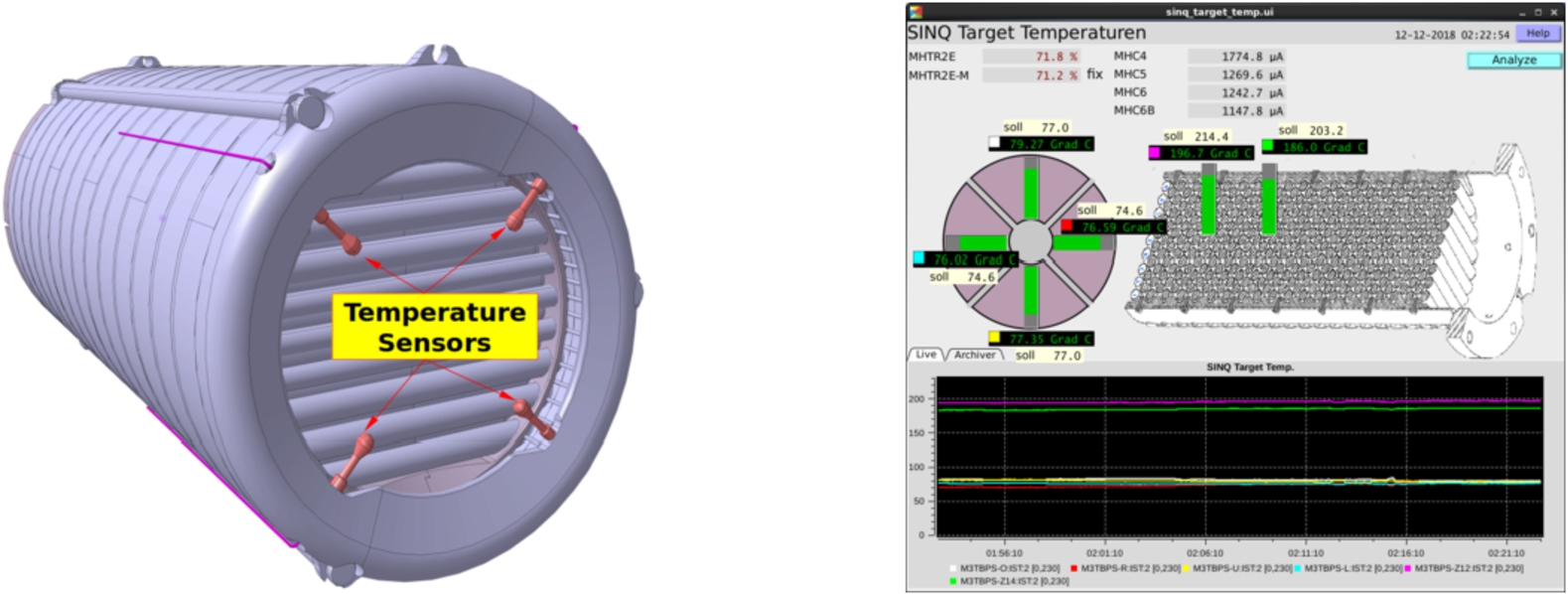
Drawing of SINQ target 13 with the new temperature based Beam Positioning System (left). The measured temperatures are displayed in the control room by the software shown on the right hand side.
As already discussed in this paper, even a very small percentage of protons missing the 6 mm wide TE leads to the formation of a pencil-like beam representing a potential threat for the integrity of the SINQ target. The philosophy of the two techniques employed so far to avoid such an occurrence, the TE transmission measurement and the KHNY30 slit, is to detect the TE-bypassing beam and interlock the machine before a damage to the SINQ target would occur. A new development has taken place that goes rather into the direction of preventing any TE-bypassing beam at all. The idea is to mill a number of grooves on the left and right sides of the TE graphite wheel following a different pattern for each side of the target. This way, a modulation of the beam current measured by the monitors located downstream of TE appears in case of a sideward drift of the proton beam on TE. The frequency of this modulation depends on the groove patterns and, for the first grooved TE prototype in operation between July and September 2019, it was chosen to be 114 and 138 Hz for the left and right side respectively. Four groove milling depths were tested, namely 0.3, 0.5, 0.7 and 0.9 mm (corresponding to 0.75, 1.25, 1.75 and 2.25% of the 40 mm target thickness respectively). The last one proved to be the best option. In Fig. 7 the grooved Target and a plot of the amplitude modulation of the beam current vs. the beam horizontal position at TE are shown. The results demonstrate that the grooved target enables to detect a beam displacement starting from ±0.7 mm from the target centre. A detailed description of the measuring technique as well as of the test results can be found in [6]. Due to the their small dimensions compared to the target size, the grooves give relatively little reason for concern about potential consequences on the long term stability of the target wheel structure. However, the integrity of the grooved target will be thoroughly checked after every target exchange.
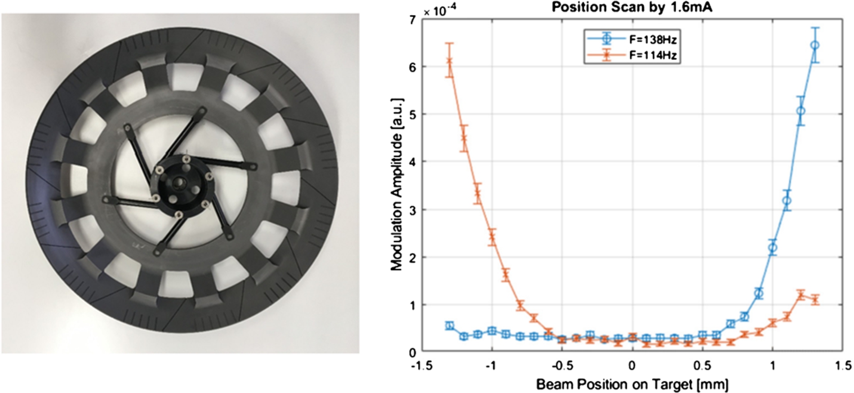
The Grooved Target-E employed for the test (left) and a plot showing the 114 Hz and 138 Hz spectral lines as function of the beam position on the target.
So far, simulations of the HIPA proton channel, including the SINQ beam line have been carried out exclusively employing the Transport/Turtle computer codes [12]. Although very fast, these tools suffer severe limitations in the description of complex geometries. Conical collimators with elliptic cross section like SINQ KHNs can be implemented, but more complicated elements like collimators KHE2-3 have to be simplified with consequent loss of accuracy. Moreover, Turtle relies on the external code Muscat, which provides parameters for multiple scattering, nuclear elastic scattering and absorption but does not include inelastic scattering. Both issues can be tackled by using a general purpose particle transport code MCNPX [9]. In order to get some preliminary results in a reasonable amount of time it was decided, as a first step, to combine Turtle and MCNPX, using the latter only for the two beam line sections where TE and collimators, but no magnetic elements, are present. This way, it was possible to exploit both the computing speed of Turtle as well as the accuracy of MCNPX as far as the interaction between particles and matter is concerned. The simulation procedure starts with 10 millions protons at the upstream end of TM. The initial beam parameters are taken from an envelope fit making use of the available beam profile measurements. Turtle tracks particles to the upstream end of TE. The resulting distribution is then used as an input for MCNPX, which, in turn, simulates the beam line section between TE and the downstream end of KHE3 (the last of the four TE collimators).
Compilation of beam transmission (in %) at different location of the TM-TE-SINQ beam line computed using pure Turtle as well as combined Turtle/MCNPX (MCNPX in the column title) simulations for TE40 and TE60. The measured transmission MHC6b/MHC2b is also displayed for comparison
Compilation of beam transmission (in %) at different location of the TM-TE-SINQ beam line computed using pure Turtle as well as combined Turtle/MCNPX (MCNPX in the column title) simulations for TE40 and TE60. The measured transmission MHC6b/MHC2b is also displayed for comparison
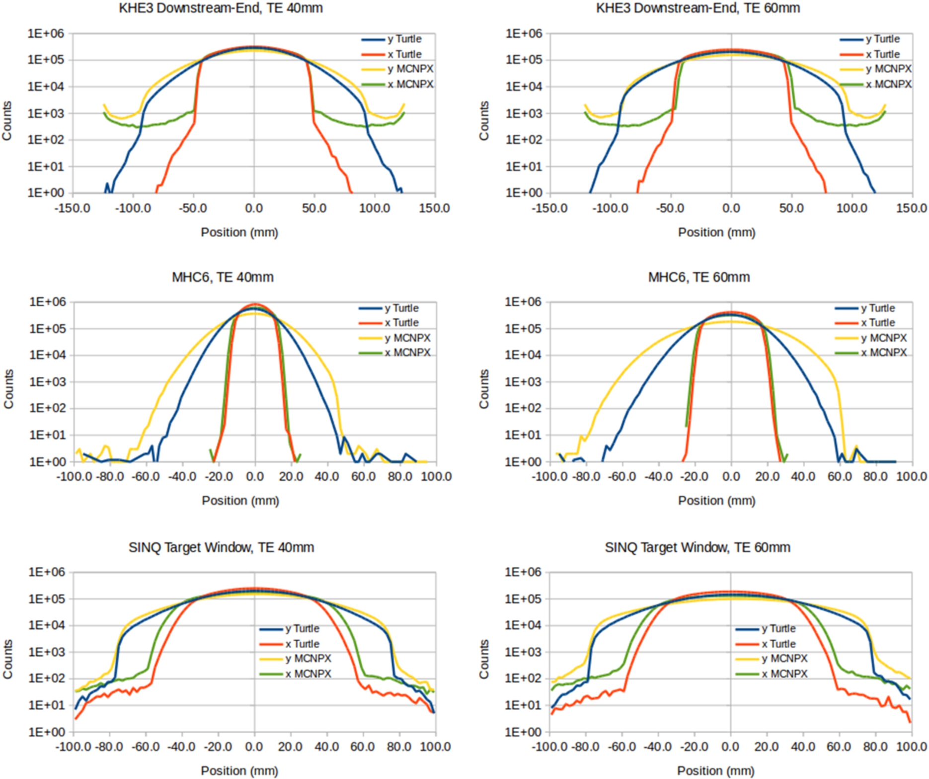
Proton beam distributions for TE40 and TE60 along the SINQ beam line obtained with pure Turtle as well as combined Turtle/MCNPX (MCNPX in the legend) simulations.
At this point Turtle takes over again, reading in the MCNPX output and tracking protons through the magnetic elements till the upstream end of KHN31 (the first out of three SINQ target collimators). MCNPX is then in charge of the very last part of the beam line, computing the losses through the SINQ collimators and dumping the beam distribution at the SINQ target entrance window. This procedure was carried out for both TE40 and TE60. In MCNPX particle parameters were written out on surface crossing without additional filtering. The resulting horizontal (x) and vertical (y) distributions, compared to the ones obtained by the pure Turtle simulation, are displayed in Fig. 8, whereas the corresponding beam transmissions are reported in Table 1. In the following analysis all percentages are relative to the initial sample of 10 millions particles. The upper plots of Fig. 8 display the situation at the downstream end of KHE3, i.e. after the last of the four TE collimators. The MCNPX distributions show huge tails both in x and y, while the Turtle distributions fall relatively fast towards zero. At this location, the beam transmission calculated by MCNPX is 4(5)% smaller than the one computed by Turtle for TE40(TE60). A deeper study has pointed out that the main difference between the two simulations happens in the collimator system KHE2-3, where for TE40(TE60) the beam absorption is around 22(30)% in MCNPX and only 15(20)% in Turtle. This huge discrepancy can be due to the simplified implemented collimator geometry as well as the absence of the inelastic scattering process in Turtle. When tracked through the beam line, the wider MCNPX distribution causes much larger losses than the Turtle one. At MHC6 (the second of the two resonators in charge of the beam current measurement) the plots show that the MCNPX distribution is much wider than the Turtle one especially in the vertical plane and the difference in beam transmission becomes 6.4(7.3)% for TE40(TE60). At this location, the computed transmission can be compared to the one obtained by taking the ratio between the values measured by the two absolute current monitors MHC6b and MHC2b. The values reported in Table 1 were obtained taking the average over the months of August 2017 for TE60 and August 2018 for TE40. It is interesting to note that the measured transmissions lie between the two computed values, i.e. none of the two simulation methods can reproduce the experimental results. Another, smaller, difference between Turtle and MCNPX is given by the estimated absorption through the KHNs collimators upstream of the SINQ target window. In this case for TE40(TE60) MCNPX predicts 1.0(1.2)% absorption, while Turtle only 0.2(0.2)%. At the location of the SINQ target, the MCNPX distribution matches very well the beam envelope fit (Fig. 2) in the horizontal plane (x), where the beam tails are largely shaped by the TE collimators. In the vertical plane (y), Turtle reproduces better the envelope fit, but only in case of TE40.
After the failure of the SINQ target number 11 in June 2016, a campaign towards an improved control and thorough understanding of the proton beam delivery to SINQ has been launched. The new diagnostic elements developed, installed and commissioned so far offer already great improvements in terms of beam loss surveillance, monitoring beam position and distribution at the SINQ target, detection of TE-bypassing beam as well as beam current measurement. New ideas are also being evaluated. The grooved TE concept proved to be a great tool to prevent the dangerous TE-bypassing beam and will be certainly pursued in the coming years aiming at its implementation in the machine protection system. The temperature based SINQ beam centring system is being further developed and an improved version is under study to be installed in the SINQ target number 14. The possibility of finally furnishing the SINQ beam with BPMs is under discussion [3]. New fast and more flexible electronics for beam loss monitors is being developed [2]. Last, but not least, a Machine Learning project aiming at automatic control of beam footprint on SINQ as well as beam interlock forecasting started at the beginning of 2019.
Parallel to the progress of the beam instrumentation, the beam line simulations are being re-thought. More complete tools like MCNPX are now employed in order to support and complement the Turtle code. The comparison between the pure Turtle and the combined MCNPX/Turtle simulations of the SINQ beam line shows a clear discrepancy among them. The main source of difference is clearly coming from the scattering in the TE collimators KHE2 and KHE3. None of the two simulations carried out so far is in agreement with the experimentally measured beam transmission. A deeper understanding of how the two tools differ in this respect is essential for the further development of this simulation study.