
Abstract
This study examined the failure mechanism of fiber-wound composite pipe and determined the optimum winding angle. Simulation models of glass fiber-wound composite pipe were established. Failure factor of the reinforced layer of fiber-wound composite pipes under internal pressure, torsion, axial tension and bending load are investigated in conjunction with the three-dimensional Tsai-Wu failure criterion. The results show that the winding angle has a significant effect on the stress distribution of the reinforced layer. The inner layer of the reinforced layer is prone to failure under internal pressure. The outer layer of reinforcement layer under torsion is the easy failure position. The failure-prone layer under tensile load is related to the winding angle. The inner layer of the reinforced layer is prone to failure when the winding angle is less than 60°, and the outer layer is prone to failure when the winding angle is more than 60°. The outer reinforced layer is prone to failure under bending loads. When the winding angle is less than 50°, the easily failed failure position is on the inside of bending. When the winding angle is greater than 50°, the easily failed position is on the outside of bending. The smaller winding angle is conducive to improve the tensile, bending and torsion resistance of the composite pipe. The larger winding angle is beneficial for improving resistance to internal pressure. The optimal winding angle range for each load is different and multiple winding angles should be used in the design to obtain a higher overall load carrying capacity. The research results can provide a theoretical basis for the improved design, manufacture and evaluation of fiber-wound composite pipes.
Introduction
With the oil well water injection, oil production and CO2 injection process of tubing corrosion resistance is becoming more and more demanding, and the traditional downhole metal tubing corrosion leakage problem has become increasingly prominent. Corrosion-resistant fiber-wound composite pipe not only has excellent corrosion resistance, but also has the advantages of flexible designability, light weight, easy to install, and can be coiled, which makes it a good substitute for steel pipe [10,28]. Much research has been conducted on the fiber-wound composite pipe. Feng et al. [6] simplified the fiber-reinforced layer cross-section of the composite pipe into a fiber rope and matrix rope structure, and investigated the effects of parameters such as fiber winding angle and fiber content on its tensile properties. Ge et al. [7] studied the influence of 0° and 90°ply angles on the bearing capacity of fiber-wound composite pipe under combined internal pressure and tensile loads by simulation. Tamer et al. [16] carried out mechanical experiments on composite pipes with different winding angles, and obtained that the optimal winding angle of the reinforced fiber was ±55°. Xia et al. [21,22] established a stress-strain calculation method for the fiber reinforced layer of composite pipe based on three-dimensional anisotropy and considering the temperature of conveying medium. Cox et al. [3] investigated the effect of structural parameters on the mechanical properties of composite pipe. Bai et al. [1,2] investigated the stress-strain relationship of fiberglass-wound tubes under different loads. Lin et al. [11] investigated the buckling instability mechanism of fiber-wound composite pipe under external pressure load based on nonlinear buckling and virtual work principle. Yao et al. [23] investigated the effect of different load application paths on the failure form of composite tubes under external pressure and bending loads. Sun et al. [18] proposed a convenient stress analysis method for composite tubes using homogenization method and derived homogenized elastic constants for composite tubes. Parnas et al. [14] proposed a computational model for predicting the mechanical behavior of composite pressure vessels based on classical plywood theory and generalized stress-strain models. Kong et al. [9] found that after the failure of composite pipe joint seals, the contamination of reinforcing fibers by the transport medium will cause a significant reduction in composite pipe burst pressure. Ding et al. [4] established a finite element model of the tensile layer of a smart composite continuous tube and investigated the influence of auxiliary cables on the mechanical properties of the tensile layer. Liu et al. [12] used numerical simulation to analyze the stress distribution of thermoplastic composite flexible pipe hot-melt joints and butt-welded armored joints under ultimate internal pressure. Hui et al. [8] summarized the current research status of fiber-wound composite pressure vessels in terms of domestic and international standards, optimal design and damage detection.
The above research mainly focuses on the stress-strain analysis of fibre-wound composite pipes and the simplification of the mechanical theory model. The analysis of the bearing capacity of fibre-wound composite pipes is mostly from stress and the failure criterion is less introduced for comprehensive analysis. Furthermore, it is generally accepted that ±55° is the optimum winding angle for fibre tapes [25], however this optimum winding angle is only valid when the ratio of hoop to axial stress is 2:1 [24]. Fibre-wound composite pipes do not necessarily meet the stress ratio of 2:1 under different working conditions, so the range of optimum winding angle under various working conditions needs to be studied in depth. Therefore, the mechanical model of glass fiber wound composite pipe is established considering the three-dimensional Tsai-Wu failure criterion in this paper. The mechanical behavior and failure factor of composite pipe under internal pressure, torsion, axial tension and bending load are studied respectively. The influence of the winding angle on the stress distribution and failure factor is discussed, and the optimum winding angle range for each working condition is proposed.
Numerical model of fibre-wound composite pipe
Fibre-wound composite pipe
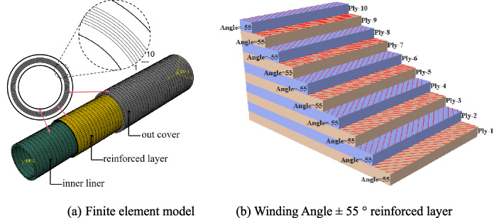
Fibre-wound composite pipe consists of a three-layer structure, from inside to outside: inner liner, reinforced layer and outer cover, as shown in Fig. 1. The three structural layers are bonded to each other by a hot-melt process. The inner liner and the outer cover can prevent the internal and external liquid penetration and thus protect the pipe body, mostly using corrosion-resistant, anti-penetration thermoplastics such as high-density polyethylene (HDPE), polypropylene (PP) and so on. The reinforced layer as the main load-bearing structure is often made of carbon fibre tape, glass fibre tape and aramid fibre tape wound at a certain winding angle alternating between positive and negative.
Finite element model
In this model, HDPE is used for the inner liner and outer cover, and glass fibre unidirectional tape is used for reinforced layer. All material parameters are the same as in a previous study [25]. The inner diameter of the composite pipe is 48 mm and the outer diameter is 69 mm. The thickness of the inner liner and outer cover is 4 mm. The reinforced layer is 10 layers, the thickness of each layer is 0.25 mm, the total thickness of the reinforced layer is 2.5 mm. The fiber winding angle is ± 55°. According to St. Venant’s principle, the length of the pipe should be at least 5 times the diameter of the pipe in order to eliminate the effects of boundary conditions [27], and the middle of the pipe body should be taken as the stress analysis area [15]. The loads for each working condition are shown in Table 1.
Structure of fiber-wound composite pipe.
Load conditions
The three-dimensional Tsai-Wu criterion [19] comprehensively considers the interaction of stresses in all directions and can be used as the basis for the reinforced layer failure of the fiber-wound composite pipe. This criterion considers that when the failure factor f is greater than 1, strength failure of the composite ply occurs, and when the failure factor f is less than 1, the composite ply is safe [7]. Therefore, comparing the magnitude of the failure factor value can indicate the degree of failure of each ply under the same load. That is, the larger the failure factor, the more likely that the composite ply will fail and the weaker the load carrying capacity of the composite pipe [7]. For example, under the action of internal pressure, one layer of the reinforced layer has the largest failure factor, which can be considered as a dangerous layer. Comparison of the relative magnitude of the failure factors of the hazardous layers to obtain the relative strengths of the bearing capacity of composite pipes with different winding angles. The first layer failure theory suggests that the failure of the entire composite layer occurs when one of the layers in the composite layup fails [26], so it is more concerned with the problem of failure-prone layers (who have a large failure factor). It is difficult to apply a load such that no composite pipe with different winding angles fails (failure factor less than 1), which requires many attempts. In order to facilitate the study, this paper does not consider the progressive damage (stiffness degradation) of the composite material after the failure of the first layer, and the model maintains the original mechanical properties of the reinforced layer after the failure factor is greater than one. The three-dimensional Tsai-Wu criterion failure factor ‘f’ can be derived from the stresses in the composite layup:
According to a previous study [19], when the material is transversely isotropic,
Fang et al. [5] conducted torsional stiffness experiments on fibre-wound composite pipe, a numerical model with the same parameters as the experimental sample pipe was established and a rotation angle of 0.4 rad was applied. The results are shown in Fig. 2, and the torsional stiffness of the verification model is in good agreement with the experimental result. The torsional stiffness 8229.95 N⋅m2/rad is obtained by the simulation method and the experimental result of a previous study [5] is 8333 N⋅m2/rad. The error is 1.24%, which shows that the simulation method in this paper is reliable and can provide guarantee for subsequent analysis.
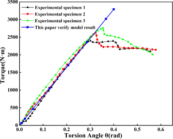
Torque-torsion angle curves.
The winding angle of the reinforcement layer is one of the most important structural parameters of the composite pipe. It is of great significance to study its influence on the mechanical response and bearing capacity of composite pipe. Therefore, the winding angle of ±20° ∼ ±80° is selected for analysis.
Internal pressure load
The composite pipe is subjected to both circumferential and axial bi-directional stresses during the internal pressure test [13]. Therefore, the internal pressure load analysis needs to consider the end force, where end force F = P𝜋R 2, R is the internal diameter and P is the internal pressure load.
The stress of the fibre-wound composite pipe subjected to an internal pressure of 20 MPa at a winding angle of ±55° is shown in Fig. 3. The maximum stresses of the inner liner and outer cover are 21.1 MPa and 9.488 MPa respectively, while the maximum stress of the reinforced layer is 230.8 MPa, which is much larger than that of the inner liner and outer cover, indicating that the reinforced layer is the main load-bearing structural layer of the fibre-wound composite pipe.
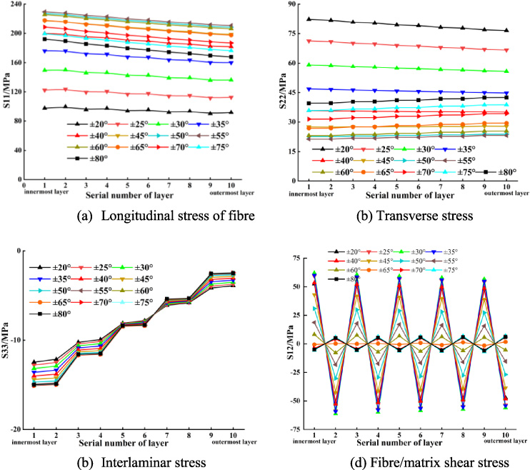
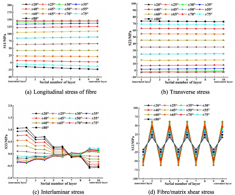
The anisotropic stresses in the reinforced layer at a winding angle of ±55° are shown in Fig. 4. Follow the paving layer from the inside to the outside, then longitudinal stress of fibre (S11) gradually decreases. The transverse stress (S22) in the vertical fibre direction increases gradually. Interlaminar stress (S33) is compressive and decreases gradually. The fibre/matrix shear stress (S12) alternates between positive and negative and the magnitude of the value decreases gradually, and the shear stresses S13 and S23 are almost zero. This is consistent with the stress variation law of the fibre-wound composite pipe in a previous study [25].
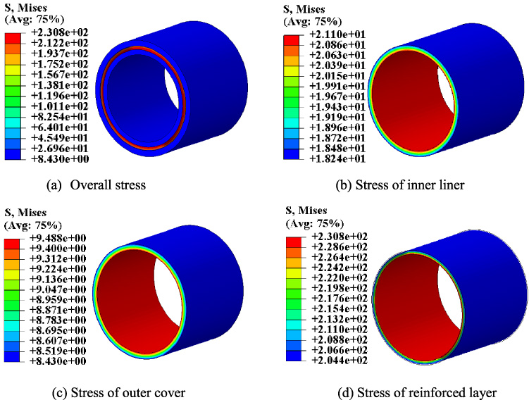
Stress distribution in each part of the composite pipes.
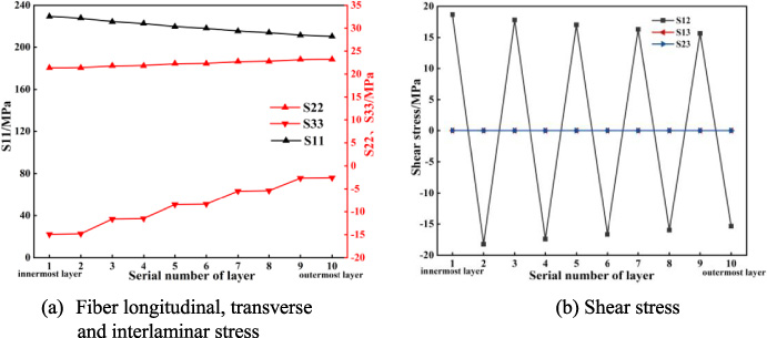
Stress distribution of reinforced layer at winding angle ±55°.
When the internal pressure is 20 MPa, the stress in the reinforced layer of the composite pipe with different winding angles is shown in Fig. 5. The longitudinal of fibre and transverse stresses are tensile and the interlaminar stresses are compressive. When the winding angle is ±20° ∼ ±80°, the longitudinal stress of fibre and interlaminar stress decreases gradually from inside to outside. The transverse stress decreases from inside to outside when the winding angle is less than ±45° and increases from inside to outside when the winding angle is more than ±45°.
Since the two adjacent layers of fibre tape are wound at opposite angles, the fibre matrix shear stress alternates positively and negatively from the inside to the outside when the winding angle is less than ±65°, and negatively and positively from the inside to the outside when the winding angle is greater than ±65°.
The interlaminar stresses and longitudinal of fibre stresses show a gradual decrease from inside to outside at each winding angle. The transverse stress and fibre/matrix shear stress are divided by ±45° and ±65°, respectively, with two trends from inside to outside. Therefore, it is not possible to consider the innermost layer of the reinforced layer as a failure-prone layer simply from a certain stress, but the influence of the stresses in all directions should be considered comprehensively by using the Tsai-Wu criterion.
Stress of reinforced layer under internal pressure load.
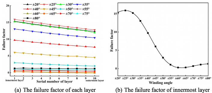
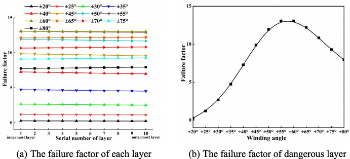
Figure 6a shows the failure factor of each layer of the reinforced layer of the composite pipe with different winding angles, and all the failure factors gradually decrease from the inside to the outside, which indicates that the inner layer of the reinforced layer is the most likely to fail.
Figure 6b shows the variation rule of the failure factor of the innermost layer of the reinforced layer with the winding angle under the internal pressure loading, the failure factor increases slightly from ±20° to ±25°, decreases rapidly from ±25° to ±55°, and decreases slightly after ±55° and reaches the minimum at about ±60°.
The transverse strength and shear strength of the composite material are much lower than the longitudinal strength of its fibres and at the same time the transverse stress value and shear stress value are relatively large in the case of composite tubes, so the transverse stress and shear stress are the main failure stress factors. Therefore, with the increase of winding angle after ±60°, and the fibre transverse (matrix) becomes the main load-bearing part of the end force, with a large increase in stress and a small increase in shear stress, and the failure factor goes up slightly. Transverse and shear stresses are relatively maximum when the winding angle is about ±25°, and the peak of the failure factor occurs, so ±25° is most unfavourable for carrying internal pressure.
Failure factor for zones after ±55° tend to be stable and small and much lower than for other zones.It can be considered that ±55° is the best winding angle to carry internal pressure from the comprehensive consideration of the difficulty of winding moulding and loading capacity.
Failure factor of reinforced layer under internal pressure load.
Shi et al. [17] note that when the pipe is subjected to internal pressure and its end forces generated by the internal pressure, the ratio of annular stress to axial stress is 2:1. Therefore, the optimum winding angle derived here is in accordance with the previously mentioned ±55° as the optimum winding angle when the ratio of annular stress to axial stress is 2:1.
In terms of the overall variation of the failure factor with angle, it can be assumed that the composite pipe with small winding angle has low pressure-bearing capacity, and the large winding angle is conducive to improving the internal pressure-bearing capacity of the composite pipe, but a too large winding angle has limited improvement on the pressure-bearing capacity, and it will also increase the difficulty of winding forming.
Figure 7 shows the stresses in the reinforced layer of composite pipe with different winding angles under the torque 2 kN⋅m. The longitudinal stress of fiber and interlaminar stress are compressive stress in the odd layer of the reinforced layer and tensile stress in the even layer. The transverse stress is tensile stress in the odd layer and compressive stress in the even layer. The fibre/matrix shear stress is positive when the winding angle is greater than ±45° and negative when it is less than ±45°. In the values of the stresses, the four stresses increase gradually from inside to outside.
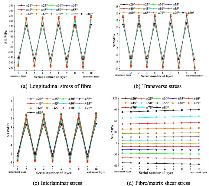
Stress of reinforced layer under torsional load.
Figure 8a shows the failure factors for each layup of the reinforced layer of the composite pipe with different winding angles under torsional loading. The failure factor of odd layers is higher than that of even layers, because the composite material has the characteristics of high tensile strength and low compressive strength in the fiber direction. The overall increasing trend of the failure factor from inside to outside for all angles indicates that the outer layer of the reinforced layer is prone to failure. This conclusion corresponds to the failure location of the reinforced layer of the fiber-wound composite pipe in the torsional stiffness experiments in the study by Fang et al. [5], which once again verifies the reasonableness of the research methodology in this paper.
Figure 8b shows the variation of the failure factor of the 9th and 10th layers of the reinforced layer with the winding angle under torsional loading. The failure factor curve shows a U shape. The failure factors in the range of ±35° ∼ ±55° are much lower than those in other zones, indicating that the optimal winding angle interval of fiber-wound composite pipe under torsional load is ±35° ∼ ±55°.
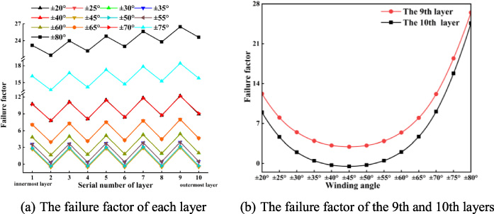
Failure factor of reinforced layer under torsional load.
Stress of reinforced layer under tensile load.
Figure 9 shows the stress of each layer of the reinforced layer when the composite pipe with different winding angles is subjected to 72 kN axial tension. As the winding angle increases, the longitudinal stress of fibre changes from tensile to compressive and the transverse stress changes from compressive to tensile. Longitudinal stress of fibre gradually decreases from inside to outside at winding angles of ±60° to ±70°, and gradually increases from inside to outside at other winding angles. When the winding angle is ± 35° ∼ ±55°, the transverse stress gradually increases from the inside to the outside, and gradually decreases from the inside to the outside at other angles.The interlaminar stress decreases from the first layer to the seventh layer. When the winding angle is less than ±50°, the interlaminar stress is compressive stress, and when it is greater than ±55°, it is tensile stress.The interlaminar stress from the 8th layer to the 10th layer generally increases. When the winding angle is less than ±50°, it is tensile stress, and when it is greater than ±55°, it is compressive stress. The fibre/matrix shear stress is negative and positive alternating and the absolute value is almost unchanged.
Figure 10a shows the failure factor of each layer of the reinforced layer when the composite pipe with different winding angles is subjected to tensile load. When the winding angle is less than ±60°, the failure factor gradually decreases from the inside to the outside, and the failure factor gradually increases from the inside to the outside when the winding angle is greater than ±60°. It shows that the failure-prone layers of composite pipes are different for different winding angles under tensile load: The failure-prone layer is the inner layer of the reinforced layer when the winding angle is less than 60°, and the outer layer of the reinforced layer when the winding angle is more than 60°.
Figure 10b shows the variation of the failure factor of the dangerous layer of the reinforced layer with the winding angle under tensile load.When the winding angle is ±20° ∼ ±30°, the failure factor increases slowly, ±30° ∼ ±60° increases rapidly, and then decreases rapidly after ±60°. The failure factor in the range of ±20° ∼ ±30° is much lower than that in other sections, indicating that the small winding angle is beneficial to improve the tensile strength of the fibre-wound composite pipe. This is in contrast to the range of optimum angles for internal pressures, which indicates that a single winding angle is not suitable for multiple loads. Therefore, it is considered that the design of the composite pipe can consider the design of the reinforced layer as a pressure-bearing layer and a tensile layer.
Failure factor of reinforced layer under tensile load.
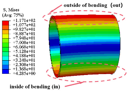
As shown in Fig. 11, the bending load produces two high stress zones on both sides of the composite tube i.e. ‘inside of bending’ and ‘outside of bending’.
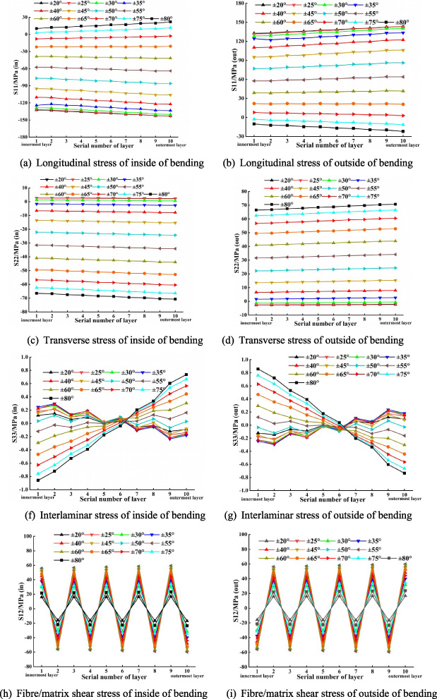
Figure 12 is the stress of each layer inside and outside the bending of the reinforced layer of the composite pipe with different winding angles under the pure bending load of 1 kN⋅m. The longitudinal stresses of fibre are equal in magnitude but opposite in direction on the inside and outside of the bending. As the winding angle increases, the longitudinal stress of fibre compressive stress changes to tensile stress on the inside of the bending, while on the outside of the bending it changes from tensile to compressive stress. The longitudinal stress of fibre gradually decreases from inside to outside at winding angles of ±65° to ±70°, and gradually increases from inside to outside at other winding angles.
Stress of reinforced layer at a winding angle of ±55° under bending load.
The transverse stress of the inner and outer sides of the bending is equal in magnitude and opposite in direction. As the winding angle increases, the transverse stress changes from tensile to compressive on the inside of the bending and from compressive to tensile on the outside of the bending. The transverse stress gradually decreases from inside to outside at winding angles of ±20° to ±30°, and gradually increases from inside to outside at the remaining winding angles.
The interlaminar stresses of the inner and outer sides of the bending are equal in magnitude and opposite in direction. When the winding angle is ±20° ∼ ±50°, the interlaminar stress on the inside of the bending changes from tensile to compressive stress from inside to outside, while on the outside of the bending it changes from compressive to tensile stress from inside to outside. When the winding angle is ±55° ∼ ±80°, the interlaminar stress on the inside of the bending changes from compressive to tensile stress from inside to outside, while on the outside of the bending it changes from tensile to compressive stress from inside to outside. Interlaminar stresses decreased overall from inside to outside in layers 1 to 6 and increased overall from inside to outside in layers 7 to 10.
The fibre/matrix shear stress of the bending inside and outside is equal in magnitude and opposite in direction, and the positive and negative alternately appear from the inside to the outside. Under the action of bending load, the longitudinal stress of fibre , transverse stress, interlaminar stress and fibre/matrix shear stress on the inside and outside of the bending show an “anti-symmetric” law, i.e. the inside and outside stresses are equal in magnitude and opposite in direction.
Stress of reinforced layer under bending load.
Figures 13a and 13b is the failure factor of inside and outside of the bending of the reinforced layer of the composite pipe with different winding angles under the pure bending load of 1 kN⋅m. The failure factor of the inside and outside of bending gradually increases from inside to outside, indicating that the outer layer of the reinforced layer is prone to failure under bending load, i.e., it is a hazardous layer.
Figure 13c shows the variation rule of hazardous layer failure factor with winding angle. Within the winding angle of ±20° ∼ ±50°, the failure factor of the inside of the bending is greater than that of the outside of the bending. The failure factor of the inside of the bending within ±50° ∼ ±80° is smaller than that of the outside of the bending. It shows that the failure position of the reinforced layer of the composite pipe is on the inside of the bending when the winding angle is ±20° ∼ ±50°, while it is on the outside of the bending when the winding angle is 50° ∼ ±80°.The failure factor of inside and outside bending is at the lowest level when the winding angle is ±20° ∼ ±30°, which indicates that smaller winding angle is conducive to improving the bending resistance of fibre-wound composite pipes.
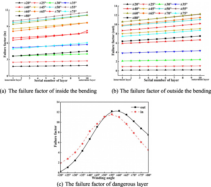
Failure factor of reinforcement layer under bending load.
(1) The inner layer of the reinforced layer of the composite pipe is most likely to fail under internal pressure loads. The large winding angle is beneficial to improve the internal pressure bearing capacity of the composite pipe, but the excessive winding angle has limited improvement on the pressure bearing capacity.
(2) The failure position of the composite pipe under torsional load is the outer layer of the reinforced layer. The optimal winding angle range of the reinforcement layer is ±35° ∼ ±55°.
(3) The winding angle affects the location of the failure-prone layer of the composite pipe reinforcement layer under tensile load. Dangerous position is the inner layer of the reinforced layer when the winding angle is less than 60°, and the outer layer of the reinforced layer when the winding angle is more than 60°. Small winding angle is beneficial to improve the tensile strength of composite pipe.
(4) Under bending load, the outer layer of the reinforced layer of the inner and outer sides of the bending of the composite pipe is most likely to fail. Failure-prone position of composite pipe is on the inside of the bending when the winding angle is ±20° ∼ ±50°, and on the outside of the bending when the winding angle is 50° ∼ ±80°. A smaller winding angle is conducive to improving the bending resistance of the composite pipe.
(5) The optimal bearing winding angle range of fiber-wound composite pipe under internal pressure, torsion, tension and bending load is different, so the reinforced layer should be multi-angle winding, that is, according to the type of load to design a different bearing layer to obtain a higher comprehensive bearing capacity.
Footnotes
Acknowledgements
This research was supported by the Key R&D Plan of Sichuan Province (2023YFS0355) and Special Postdoctoral Funding from Sichuan Province.
Conflict of interest
None to report.