
Abstract
BACKGROUND:
Upper-limb rehabilitation robots have become an important piece of equipment in stroke rehabilitation. The design of exoskeleton mechanisms plays a key role to improve human-robot interface in the upper-limb movements under passive and active rehabilitation training.
OBJECTIVE:
This paper proposes a novel of the 7-DOF (RR-RR-PRR) under-actuated exoskeleton mechanism based on the characteristics of the upper-limb movements in both of active and passive training. This aim of the proposed work is to improve human-robot interface in rehabilitation training with robots.
METHODS:
Firstly, the characteristics of active and passive movement training are analyzed depending on the human upper-limb model. Then, a novel 7-DOF (RR-RR-PRR) exoskeleton mechanism is proposed based on the analyzed characteristics. After that, kinematical performances of the proposed exoskeleton are analyzed on the workspace, manipulability and manipulability ellipsoid by compared with the common exoskeleton configuration of the 7 DOFs (RRR-R-PRR) mechanism. In the end, the prototype is manufactured and tested by undergoing the experiments of single-joint passive movement training and multi-joint active movement training. The human-robot interface of the proposed exoskeleton is demonstrated by root mean square error, Pearson correlation coefficient, and the time-delay difference.
RESULTS:
The results of the kinematical performance show that the effective workspace and the flexibility of the exoskeleton with the proposed configuration are increased by 10.44% and 1.7%. In the single-joint passive movement training experiment, the root mean square errors are 6.986, 7.568, 5.846, and Pearson correlation coefficients are 0.989, 0.984, 0.988 at the shoulder joint and the elbow joint, respectively. The time-delay differences are not beyond 3.1%. In the multi-joint active movement training experiment, the root mean square errors are 9.312 and 7.677, and Pearson correlation coefficients are 0.906 and 0.968 at the shoulder joint and the elbow joint, respectively. The time-delay differences are not beyond 3.28%.
CONCLUSIONS:
The proposed 7 DOFs exoskeleton mechanism shows uniformity with that of the common exoskeleton on the same rehabilitation trajectory which is effective to improve human-robot interface under passive and active rehabilitation training.
Keywords
Introduction
Stroke is the leading cause of disability in adults, the number of stroke patients worldwide has increased dramatically in recent decades. Against such a background, more and more attention is paid to the quality of stroke patient’s life, especially the upper-limb dysfunction related to physical activity and daily life. For most of them, physical exercise training can restore their motor function [1]. Long-term intensive rehabilitation training will accelerate the recovery process of patients [2]. Compared with rehabilitation therapists, the upper-limb exoskeleton rehabilitation robots have been widely used in the rehabilitation training with the characteristics of high intensity, good repeatability and strong interaction [3].
The upper-limb exoskeleton rehabilitation robot is mainly divided into series type and parallel type according to the mechanical structure. The upper-limb exoskeleton with parallel mechanisms, such as SPM [4], BONES [5], ExoArm [6], the shoulder complex linkage mechanism [7], the 2-DOF parallel actuated exoskeleton [8] and MAHI EXO-II [9]. Compared with the series exoskeleton, the parallel exoskeletons have the advantages of compact structure and the capability of complex movement with fewer motors, but they are difficult to adjust the structure dimension and they also lack sufficient strength. Although the application of parallel mechanisms in the upper-limb rehabilitation brings new concepts of decreasing motors, it limits the kinematical performances in workspace and manipulability.
There are two main configurations of this series of exoskeleton robots. One type is an exoskeleton configuration (RRR-R, Here, R represents the active joint and the revolute pair. There are three rotation DOFs at the shoulder joint and one rotation DOF at the elbow joint. Each joint is designed as a functional module and link together to implement the functions of the whole upper-limb. The symbol ‘-’ presents the exoskeleton.) with three active joints at the shoulder joint and one movable joint at the elbow joint. This type exoskeleton configuration mainly includes ANYexo [10], Hommory [11], MGA [12], MEDARM [13], ARAMIS [14], ABLE [15] and IDEAS [16]. The above researches improve the DOF and movement performance of the exoskeleton by adding rotating joints or sliding joints on the basic configuration of RRR-R. The RRR-R configuration has a compact structure. It can move in any direction with 3 DOFs in the shoulder joint, so it is competitive to improve the human-robot interface. However, this structure generally requires at least four motors to control the exoskeleton, which increases the cost of the exoskeleton and makes the control strategy more complicated. The other type is a configuration (
In addition, rehabilitation therapy characteristics are important bases for the design of existing upper-limb rehabilitation robots [26, 27] due to the different characteristics of active movement training and passive movement training. The requirements of low cost, high kinematical performances and active and passive rehabilitation training should be considered in the optimal design of effective rehabilitation exoskeleton. Therefore, this paper proposes a novel of 7-DOF exoskeleton configuration based on the characteristics of the upper-limb movements under active and passive movement training for the stroke patients in order to reduce the costs of driven motors, improve human-robot interface.
Mechanical design
The characteristics analysis of active and passive movement training
The functional anatomy of the upper-limb is the base of designing an exoskeleton with the better human-robot interface performance. Recently, the kinematical of the upper-limb has been modeled by using several methods. In general, the shoulder, the elbow, the wrist joints and the forearm structure are included in the design of the upper-limb exoskeletons. Shoulder joint is often modeled as a spherical joint with 3 DOFs to implement the movements of flexion/extension, abduction/adduction, and the internal/external rotation [28]. The elbow joint is commonly modeled as a revolute joint with 1 DOF to perform the movement of flexion/extension. Wrist joint is also considered as a universal joint with 2 DOFs to perform the flexion/extension and abduction/adduction movements. The forearm structure is simplified as a revolute joint with 1 DOF to perform the pronation/supination movements.
For 95% of the population, the range of motion (ROM) required for activities of daily living is derived from the maximum values of the related work [29, 30, 31] and translated to the ISB system [32] as shown in Table 1. The wrist joint has little effect on the workspace of the human upper-limb, so it needs to maintain specific physiological position.
The ROM of the upper-limb joints in the ISB system
The ROM of the upper-limb joints in the ISB system
According Zhu et al. [33], therapeutic training can promote the recovery of athletic ability and learning ability for stroke patients. Therapeutic training includes two kinds of training approaches. They are active movement training and passive movement training. Active movement training is the training that the patient actively completes in the form of muscle contraction, which requires neither assistance nor overcoming external resistance during training. Passive movement training refers to the help of external forces, such as the strength of other people, patients’ healthy limbs or equipment, to help muscles and joints to restore their functions. However, active and passive movement training in the procedure of rehabilitation has shown different movement characteristics with the robots’ assistance. In the passive movement training, the robots will drive the patients’ arm to implement the specific movements combined the shoulder joint and the elbow joint. The DOFs on flexion/extension and abduction/adduction of the shoulder joint, and the DOF on the flexion/extension of the elbow joint should be driven strictly by the robot because of the weak muscles. For instance, as shown in Fig. 1a, the positions and the direction of the blue arrows indicate that the external forces produced by the robot to drive the human joints. In the active movement training, the robots will follow the patients’ arm movements. The DOFs on the shoulder joint and the elbow joint should be free in case of restricted movements. Therefore, there are three DOFs on the shoulder joints, one DOF on the elbow joint, one DOF on the forearm and three DOFs on the wrist joint as shown in Fig. 1a. Unfortunately, there are a lot of patients who need to do the active movement training but do not have enough muscle strength. The robot exoskeleton should combine the passive movement training characteristics and the active movement training characteristics simultaneously. The characteristics on driving and the free DOFs should be optimized strictly in the same robot exoskeleton. Such this, the number of the active DOF and the number of the passive DOF for an exoskeleton should be discussed before its configuration design. The more numbers of the active DOFs the more movement limitations. The fewer active DOFs the more movement freedom and the more dangerous in rehabilitation training. On the other side, the more numbers of the active DOFs the more cost of the exoskeleton. This paper discusses a 7-DOF exoskeleton with 2 active DOFs based on the characteristics of the active movement training and the passive movement training. Therefore, as shown in Fig. 1b, the two active DOFs (the green rotation arrows) are placed on the flexion/extension of the shoulder joint and the elbow joint in order to implement the passive movement training. The reason for the choice is that the movements of flexion/extension of the shoulder joint and the elbow joint are main loads of the human arm than the others [34, 35]. The other DOFs (the blue rotation arrows) of the human arm are set to be the passive DOF in order to improve the freedom in active movement training procedure.
The human upper-limb model. (a) The 7 DOFs of the model. (b) The active and passive DOFs of the model.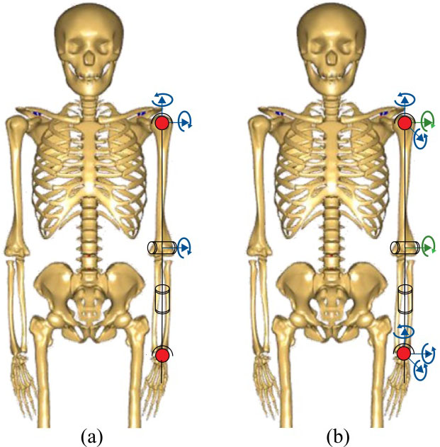
The International Society for Biomechanics (ISB) recommends that the three DOFs at the shoulder joint are presented as three serial rotations around the vertical axis, they are including rotation of
The configuration (a) Common configuration with RRR-R at shoulder and elbow joints. (b) New configuration with RR-RR at shoulder and elbow joints.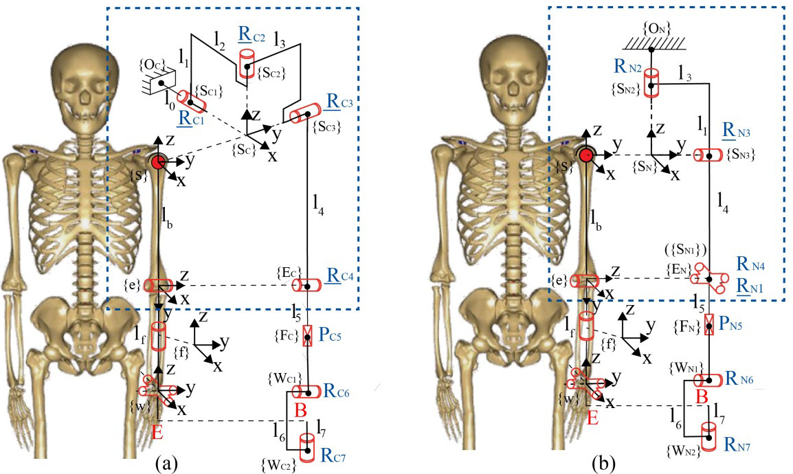
The structure configuration is important to design the exoskeleton mechanism because the kinematical performance should inflect the human-robot interface. Traditionally, the 7-DOF upper-limb exoskeleton is designed in detail on the structure of shoulder and elbow joint. As what mentioned above, there are 3 DOFs on the shoulder joint that is often designed with RRR configuration, and there is 1 DOF on the elbow joint that is often designed with R. Therefore, the
Based on the previous analysis, a new R
Kinematical performance analysis of the 7-DOF upper-limb exoskeletons
In this work, three kinematical performance indexes, which are the workspace, manipulability and manipulability ellipsoid, are chosen to assess the human-robot interface for the proposed exoskeleton. The rationality of the design structure is verified by comparing the performance of the RR-RR-PRR structure and the RRR-RR-PRR structure. Since the configuration of the wrist joint has little effects on the kinematical performance of the exoskeleton, the reference configuration is designated as RRR-R-PRR, as shown in Fig. 2a. For the convenience of description in the following paper, the RRR-R-PRR and the RR-RR-PRR are represented by Co-C (common configuration) and Co-N (new proposed configuration) (Here, Co represents configuration, C represents common while N represents new proposed), respectively.
Workspace analysis
The workspace refers to the space formed by the points of all positions that the robot’s end-effector can reach in the basic coordinate system. The workspace of the human upper-limb and two configurations are established to make the movement space of the exoskeleton satisfy the movement space of the human upper-limb as much as possible. Firstly, in the ISB system, the joints of the exoskeleton are restricted by the DOFs of the upper-limb joints to ensure safety when using the exoskeleton, as shown in Table 2. Secondly, the joints and the two configuration angles of the upper-limb are established using the Monte Carlo method [36]. Finally, the angles are substituted into the kinematic equation to obtain the workspace of the upper-limb and the two configurations, as shown in Table 3. The red space in the table represents the workspace of the upper-limb. The blue space and the yellow space are the workspace of Co-C and Co-N. It can be seen that, compared with the workspace of Co-C, the workspace of Co-N has a higher degree of coincidence with the upper-limb workspace.
The angle of the upper-limb and exoskeleton joints
The angle of the upper-limb and exoskeleton joints
The workspace of the upper-limb and the two configurations
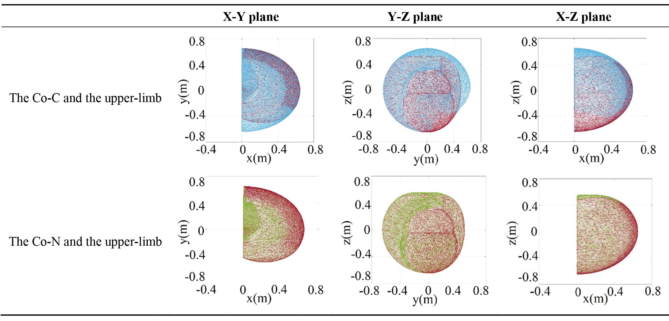
To quantify the differences, the workspace of the two different configurations are filtered through the boundaries of the human upper-limb workspace. The result is that the effective position points (the workspaces of the two configurations for the human upper-limb can reach the total workspace) of Co-C are 290119 and the effective position points of Co-N are 273536. Summation points of per point cloud are 400000. Therefore, the percentage of the effective workspace of Co-C is 75.52% and the percentage of the effective workspace of Co-N is 68.38%. It shows that the proposed configuration increases the effective workspace by 10.44%.
The workspace of the exoskeleton reflects the kinematical performance of the rehabilitation robot to a certain extent. However, due to the high flexibility of the upper-limb, the exoskeletons need to be flexible enough to improve the effect of the rehabilitation. Manipulability means the ability of the exoskeleton to change its position and orientation, that is considered to be a quantitative and performance measure of configuration selection of rehabilitation robots [37]. Manipulability analysis of Co-C and Co-N is performed as follows.
Jacobian matrix
Generally, the input of the Jacobian matrix can be checked for operability. For a revolute joint, we calculate that by
The Jacobian matrix of a prismatic joint can be computed by
Where,
The manipulability measure [37, 38], defined as
The
Due to the difference between the manipulability peaks of different robots, for the convenience of comparison, the relative manipulability is defined as
Where
To compare the manipulability of Co-C and Co-N, the values of
The details of the subject
The area with
During upper-limb rehabilitation training, the probability that the end of the exoskeleton reaches the edge of the workspace is less than that inside of the workspace. Therefore, the figures of relative manipulability combined with workspace are plotted separately to compare the level of flexibility in the whole domain, as shown in Fig. 3. The color of the workspace is closer to red, the value of
The figures of relative manipulability combined with the workspace. (a) Co-C. (b) Co-N.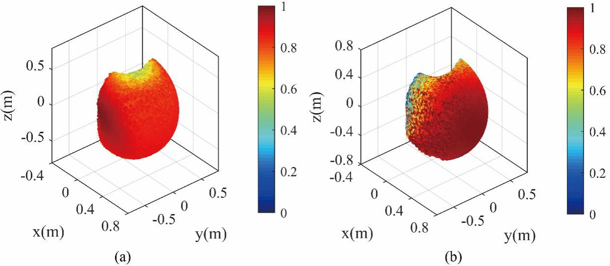
As shown in Fig. 3, the operability in both configurations are situated at the edge of the workspace, with little impact on global flexibility. However, global
Circular motion is common during rehabilitation exercises, and multiple joints can be trained at the same time. Based on the kinematical model of human upper-limb, an arc trajectory is established and divided into 10 sample points. According to the Newton-Raphson method [39], the inverse kinematical solutions of two joint configurations are obtained, and the kinematical performance of two upper-limb rehabilitation robots on the arc is analyzed.
The joint angle values
The joint trajectory of the upper-limb is set between two joint configurations. The initial joint position is set to
Manipulability ellipsoids for Co-C and Co-N.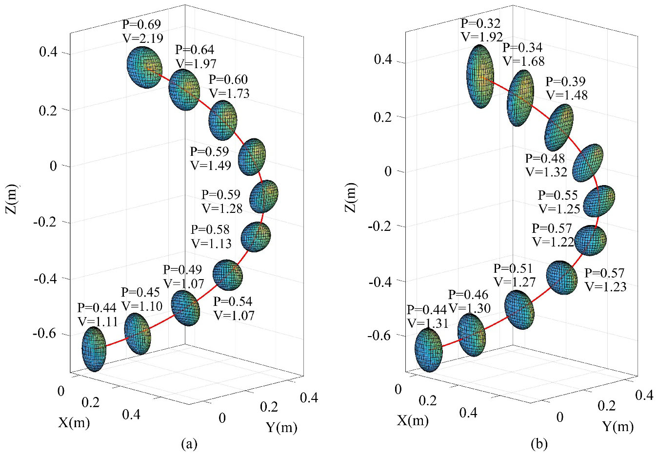
The manipulability ellipsoid is a geometric visualization tool that determines in which directions and to what extent the robot’s end-of-motion ability will be weakened. It can be used to determine the easiest and most difficult specific orientation of the robot’s movement. The volume of the maneuverability ellipsoid is proportional to the maneuverability index, which can indicate the degree of maneuverability in the visual operation space, that is
The ratio of the shortest semi-axis to the longest semi-axis of the manipulability ellipsoid P describes the kinematical performance of the exoskeleton in all directions. When the ratio P is closer to 1, the exoskeleton is easy to move in any direction, the robot is isotropic. Therefore,
The manipulability ellipsoid volume can directly represent the kinematical performance of the exoskeleton in a certain posture. The volume is larger that represents the performance is better. Therefore,
The manipulability ellipsoids corresponding to each step of the joint trajectory are obtained by MATLAB, as shown in Fig. 4. The manipulability ellipsoids of these two configurations are drawn on the corresponding sample joints. The size of the ellipsoids is reduced by 25 times for the convenience of expression. It is found that the values of P and V of Co-C and Co-N are close as a whole. The values of Co-N are larger than that of Co-C in the early stage of the movement, and the results are opposite in the later stage of the movement. The P values of Co-N are much larger than 0, which means the exoskeleton cannot reach the singularity. In summary, the kinematical performance of Co-N is roughly the same as that of Co-C, which proves the rationality of Co-N.
Implementation of the prototype
The structure of the upper-limb exoskeleton robot verified above is designed in detail in this section. The robot prototype consists of a base, a cantilever beam, and an exoskeleton body as shown in Fig. 8. The entire exoskeleton connection cantilever is installed in front of the driving lifting column at the base to accommodate different height. A certain range of sliding can be carried out from the base to adapt to different shoulder width and the switch between left-arm and right-arm. The robot is used with the left arm as shown in Fig. 5.
The system of the upper-limb rehabilitation robot.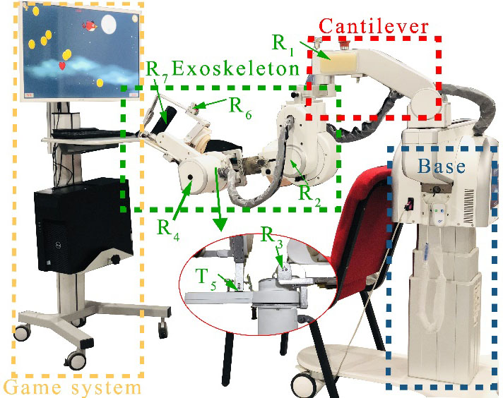
The
A series of experiments are conducted on a 26-year-old healthy male subject to evaluate the ability of the active and passive rehabilitation training on single-joint movement and multi-joint movement [42], the details of the subject as shown in Table 4. The study is approved by the ethical review board of Shanghai University of Medicine and Health Sciences (Study No. 2019-ZYXM1-04–420300197109053525). The system can measure the ROM of the shoulder joint, the elbow joint and the wrist joint of a person who sits on a common chair playing a virtual reality game. We set up seven sensors on the human upper-limb to accurately measure the joint angles: two inertial sensors located at the upside and downside of backbone, and five inertial sensors located at the upper-limb (shoulder, upper arm, forearm, palm, and hand), respectively. All of the sensors in this system can measure the angles in x-, y- and z-axis. The flexion/extension and adduction/abduction of the shoulder joint, the flexion/extension of the elbow joint and the flexion/extension and internal rotation/external rotation of the wrist joint are performed respectively and joint angles are collected in real time. We define that the cycle of motion is between the attainable maximum ROM of the corresponding DOFs, for instance, the flexion and the extension. Each couple motion has been done for 50 cycles. The accelerate and decelerate cycles are not included in the 50 cycles due to instability problems.
Experiments of single-joint movement
The single-joint exercise test is designed to verify the ability of the passive rehabilitation training. Setting three groups of experiments to test the single-joint motion characteristics between the passive motion of the human arm and the active motion of the exoskeleton arm, as shown in Figs 6–8. These test motions include flexion/extension of the shoulder, adduction/abduction of the shoulder, and flexion/extension of the elbow. The motion analysis system tests the motion angles of the human arm in real-time. Two groups of motion angles of each group experiment are compared together. The meaning of the root mean square error and Pearson correlation coefficient are utilized to describe the difference of the rotation angles between the human and the exoskeleton at the same temporal points. It is proved that the root mean square error and Pearson correlation coefficient are also being utilized to verify the human-robot interface [43, 44, 45]. The smaller of the root mean square the better human-robot interface. The value of Pearson correlation coefficient is closer to 1, the human-robot interface is better. Therefore, this paper utilizes the root mean square error and Pearson correlation coefficient to verify the human-robot interface.
Single-joint movement experiment for shoulder flexion/extension movement.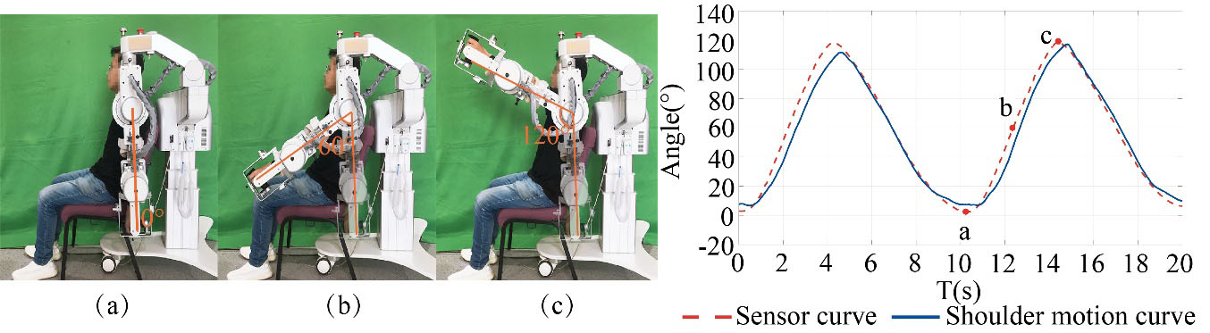
Single-joint movement experiment for shoulder abduction/adduction movement.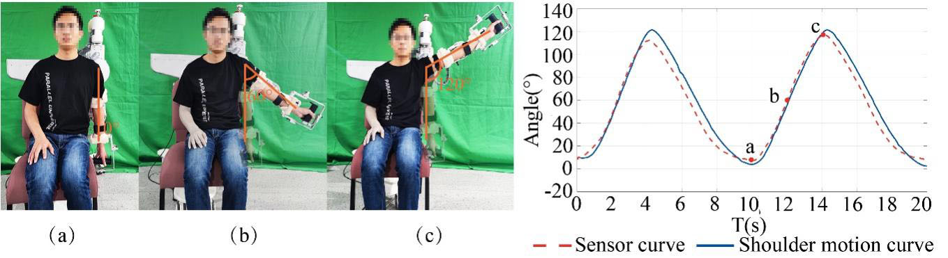
Single-joint movement experiment for elbow flexion/extension movement.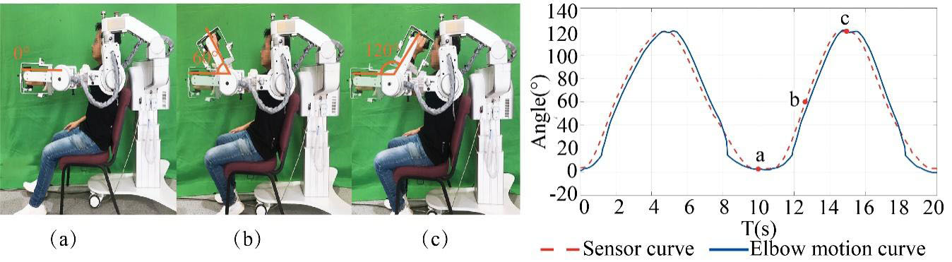
Root mean square error and Pearson correlation coefficient are used to analyze the motion error between the human arm and exoskeleton, as shown in Eqs (7) and (8).
Where,
Where,
The experiments of multi-joint movement (a) The game interface of the multi-joint rehabilitation training. (b) Analysis of the cooperative capability of the exoskeleton for flexion/extension of the shoulder. (c) Analysis of the cooperative capability of the exoskeleton for flexion/extension of the elbow.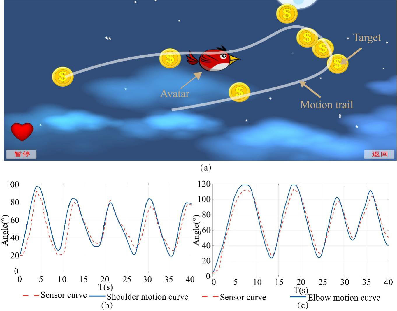
The multi-joint exercise test is designed to verify the ability of active movement training of the proposed upper-limb exoskeleton. The healthy male subject as mentioned above wears the exoskeleton to play a virtual reality game, as shown in Fig. 9a. In this model, the user performs an active joint movement with the help of the exoskeleton. The human upper-limb are assisted by the exoskeleton to resist gravity during the movement, and the bird on the screen is driven by the angle change signal of the exoskeleton joints to eat randomly generated gold coins. The white curve is the partial trajectory of the motion. This process records the changes in the angles of the exoskeleton and upper-limb joints. The flexion and extension movement of the shoulder joints of the exoskeleton and the human upper-limb are shown in Fig. 9b. The elbow joint movement curve is shown in Fig. 9c. The blue line is the real-time angle values obtained by the shoulder pose sensor and the red line is the real-time angle values obtained by the motion analysis system. The
Discussion
The 7-DOF configuration with 2 active DOFs proposed in this paper is kind of configuration is an underactuation, and it cannot be completely controlled. In order to improve the human-robot interface, this paper proposes a novel configuration (RR-RR-PRR) based on the specified DOFs by synthesizing the characteristics of active movement training and passive movement training. As for the novel configuration, the DOFs of adduction/abduction, the internal/external rotation on the shoulder joint, and the DOFs on the forearm and the wrist joint are fixed to ensure the passive movement during the passive movement training procedure However, all of the passive DOFs are released because the human arm can provide the external actives DOFs in the active movement training procedure Under the restriction of this condition, fewer motors should promote the economy of the proposed exoskeleton. However, the underactuation characteristics of the exoskeleton will bring some disadvantages in motion control, such as the workspace, the manipulability. The workspace of the exoskeleton should keep the same one as a human being. Unfortunately, most exoskeleton (e.g. [4, 5, 6]) could not reach the human beings because their configuration is limited. This paper analyzes this workspace and manipulability ellipsoid by comparing with the common configuration RRR-R-PRR. It is noted that the workspace of the proposed configuration is increased by 10.44% even under the same constriction conditions [15, 16]. On the other hand, the same workspace is achieved by increasing the number of active degrees of freedom. Thus, the economic characteristics of the exoskeleton will be affected (e.g. [10, 12]). The results also indicate that the configuration could improve the man-robot interface on the aspect of workspace. In addition, the human-robot interface can be expressed by the movement characteristics, i.e. the manipulability or manipulability ellipsoid. According to the computing results shown in Section 4, it is found that the values of P and V are close as a whole. It indicates that the exoskeleton can follow the movement of human arm in active movement training and drive the human arm fluently than the common configuration that owns the same active DOFs. In operating experiments of the prototype, the single-joint movement experiment proves the end effector trail of the prototype has been following the human arm when they are moving together. The time-delay differences between both curves are not beyond 3.1%. The man-robot interface of 7-DOF exoskeleton can be improved by this design. However, it is obvious that the increasing number of DOF can have a better interface (e.g. Hommory [11]). Another solution would be to improve the man-robot interface. Unfortunately, the number of active DOF could be increased in order to implement it. Therefore, it is one solution of changing the position of DOF under the same active DOF. The proposed exoskeleton can be applied to help patients complete specific training tasks in active or passive movement training, so as to achieve clinical rehabilitation of patients with upper-limb dysfunction or functional limitations. It is valuable to verify which DOF can be changed in case to improve better man-robot interface in the design of rehabilitation exoskeletons.
Conclusions
In this paper, a novel type of exoskeleton with RR-RR-PRR configuration for stroke patients with upper-limb dysfunction is proposed in passive and active movement rehabilitation training towards improving the human-robot interface. The number of DOF of the exoskeleton is 7, while the number of the active DOF is 2. Therefore, this mechanism is an underactuation. In order to verify the rationality of the proposed configuration, the kinematical performance parameters of the configuration including workspace, relative manipulability and manipulability ellipsoid are analyzed and compared with those of the RRR-R configuration to evaluate the kinematical performance of the proposed configuration. The effective workspace and the flexibility of the exoskeleton with the RR-RR-PRR configuration are increased by 10.44% and 1.7%. Finally, a 7-DOF exoskeleton rehabilitation robot for upper-limb is designed according to the RR-RR-PRR configuration. Two sets of the experiments of single-joint passive movement training and multi-joint active movement training have been proceeded in order to show the human-robot interface of the proposed exoskeleton. In the single-joint passive movement training experiment, the time-delay differences are not beyond 3.1%. In the multi-joint active movement training experiment, the time-delay differences are not beyond 3.28%. In addition, safety plays a key role in the design of rehabilitation robots. For patients, it is necessary to avoid any risks. Kinematical performance analysis and the experiments have also verified the safety of the exoskeleton [46, 47]. The experiments also show the proposed upper-limb exoskeleton has good human-robot interface during active and passive movement training.
Footnotes
Conflict of interest
None to report.