
Abstract
Recent problems with large head metal on metal hip replacements have spiked renewed interest in the head-neck junction. A thorough knowledge of the principles of the locking mechanism, the assembly technique and affecting factors on the strength of this junction is needed. Currently a confusing variability in terms is used to describe this junction. This overcomplicates an already complex issue. The purpose of this literature review is to collect and list the different terms used and to propose a uniform terminology. Two authors independently searched the electronic databases of PubMed, CINAHL and MEDLINE with specific key words and combinations according to the PRISMA guidelines. The initial search yielded a total of 518 articles with ultimately 53 articles included in the present analysis. No consensus for a uniform term for the 2 sides of the head-stem junction was found. Since there is already pronounced variability in taper designs between different manufacturers (even so similarly named, e.g. “12/14”), a uniform terminology could be the first step to simplify the situation. “Male” and “female taper” is proposed as the appropriate terminology for the stem and head junction in hip replacement, respectively. The importance of the assembly technique understanding the principles of the locking mechanism is emphasised.
Introduction
In the past 4 decades modularity at the head-neck junction has largely replaced the monobloc femoral components initially used in total hip replacements. Modularity enables the surgeon to use different materials, diameters and lengths for the femoral head providing options to fit the joint replacement according to the patient needs. Furthermore, during revision surgery the head can be removed achieving better exposure and enabling a change in material, neck length and head diameter (1-2-3). There are some disadvantages though. By using a modular prosthesis, an additional interface is introduced which bears the risk of corrosion and wear. In large head metal on metal hip replacements, wear at the modular head-neck junction or taper adaptor is speculated to be a significant contributive factor in the development of adverse tissue reactions (4, 5). Retrieval studies have shown evidence of damage at the head-neck junction in patients suffering catastrophic tissue damage in association with minimal wear of the bearing surface (6-7-8-9). The enlarged lever arm, in especially large diameter metal on metal prosthesis, stresses the junction causing wear and consequent release of metal debris with potential formation of pseudotumours (7).
In the literature a plethora of terms is used to describe the head-neck junction. The purpose of this literature study is to collect and list the different terms used for the head-neck junction and to propose a uniform terminology.
Methods
We conducted a systematic review of the available literature according to PRISMA guidelines (10). The electronic databases of PubMed [PW and FW], CINAHL [PW] and MEDLINE [PW] were searched by 2 authors independently closing 1 January 2014. Search terms used were head-neck junction, taper, trunnion and cone. Each search term was combined with the term “and total hip” to exclude articles not regarding the head-neck junction in hip replacements. There was no restriction in date, origin or language of publication. The inclusion criteria were as follows: 1) all studies (irrespective of the level of evidence); 2) used in total hip replacements; and 3) full text available. Exclusion criteria were: junction in neck-stem modularity (instead of head-neck or in addition); and taper junction not concerning total hip replacements (e.g knee, dental care). The selected full text papers were reviewed again to determine if they focused specifically on the head-neck junction. The reports were stratified by frequency of use of various terms for the head-neck junction. We aimed to identify the most commonly used name for the stem and head side of the head-neck junction.
Results
The search strategy is listed in Figure 1. Initial search yielded a total of 518 abstracts. The search strategy left ultimately 53 articles ready for analysis (2, 6-7-8-9, 11-12-13-14-15-16-17-18-19-20-21-22-23-24-25-26-27-28-29-30-31-32-33-34-35-36-37-38-39-40-41-42-43-44-45-46-47-48-49-50-51-52-53-54-55-56-57-58). The terms used to describe the head neck junction often were used interchangeably, frequently only a part of the junction was described. The various terms used in the selected articles to define the male and female part of the junction as well as the junction itself are listed in Table I with their occurrence rates.
Different terms used to describe the male part, junction and female part

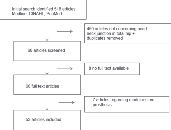
Flow chart; methodology to obtain articles on head neck junction, PRISMA algorithm.
Discussion
Reviewing the articles it became obvious that different terms are used to describe the junction between head and stem. Obviously uniformity in terms enables a more clear and productive discussion on any matter. As it has become more important that the principles of the locking mechanism are clear to the surgeon, it is apparent that the variability in terms in literature overcomplicates an already complex issue.
Since it became clear that no uniformity in terms can be found in literature we sought to find the most appropriate term. Mechanically, the expression ‘trunnion’ and ‘bore’ should be omitted since they refer to cylindrical structures. Since the head-neck junction is uniformly tapered the terms male and female taper seem the more mechanically appropriate terminology for respectively the stem and head side of the junction. The term ‘cone’, although mechanically correct only applies to the female side and is much less used than taper. The nominal results from our literature search reflect the ambiguity in the literature and not necessarily the order of preferred terms. We propose the use of ‘male taper’ and ‘female taper’ as preferred terms being the most mechanically correct and also adequately supported in the literature.
The principle of the tapered locking mechanism was invented by Stephen Morse in the 1860s (59). It refers to a self-interlocking junction first applied in milling machines and lathes presses. The principle of the Morse taper is that of a cone in a cone (Fig. 2). The 2 cones have different angles and, when compressed during assembly, will interlock. The geometry of a taper is defined by the taper angle, taper length and distal or proximal diameter, roundness, straightness, surface finish and material. In hip arthroplasty in Europe, the current standard is a so called 12/14 (5 ̊ 43 min 30 s) taper (meaning the male taper), also referred to as “Eurocone”. Originally this indicated a taper with a diameter of 14 mm at the base (distal) and 12 mm at the tip (proximal) for a taper with a length of 2 cm (8, 60). But in practice, the tapers differ due to a different tip diameter and taper length (Fig. 3). Mostly these differences can not be identified visually by the user. This is the reason why female and male tapers of different manufacturers should not be joined.
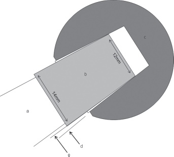
Example of a Morse 12/14 taper in total hip replacement. There is a negative mismatch (angles e-d<0). a: stem; b: male taper; c: head; d: angle female taper; e: angle male taper
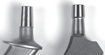
Photograph of two 12/14 tapers from 2 different companies, same taper with different length and surface finish.
All of these dimensions contain certain variations, given by the specified manufacturing tolerances (e.g., ±2 angular min for the female taper). For nominal identical taper angles, in reality either a positive or negative taper angle difference is achieved due to these tolerances, influencing the stress distribution between male and female taper (61). For example, in ceramic heads the contact area of stem and head is near the center of the head. The male taper is therefore designed with a slightly smaller angle (∼1 angular minute) than the female taper, creating a negative taper angle difference. This results in the maximum interference at the small end (tip) of the taper closer to the center of the head resulting in less stress (31). This fixation method is called “top loading”. Cales et al explained the risks and advantages of standardisation of male and female tapers in modular hip prostheses (62). However, until today, no standardisation has been achieved by DIN, ISO or ASTM. The similar notation (“12/14” or “EURO”-taper) as such is therefore highly misleading.
Another factor is the roughness and the profile of the taper surface. Most male tapers have a ridged surface that has been machined into the material in order to prevent local stress concentrations using ceramic heads. There is a commercial benefit in producing one type taper only. Assembling a metal head on a taper optimised for a ceramic head can increase the potential for corrosion at the taper interface. In modular large head metal on metal prostheses, the horizontal lever arm distance is increased, which increases the torque moment at the taper interface facilitating micro motions and fretting wear at this interface (7). Recently Panagiotidou et al published a paper about the association of enhanced wear and corrosion with the contact area and surface finish (45). During the last 2 decades, the taper has become shorter in length and its diameter was decreased to increase head neck ratio in order to prevent impingement and increase range motion. The contact area of the taper interface however decreases, leading to enhanced wear and corrosion. It should be emphasised that tapers may appear identical but vary between different companies, material, length, diameter, angle, surface finish and are designed for specific purposes.
The strength of the taper lock does not only depend on its design. A proper assembly technique is required to ensure a strong connection. First of all, the taper needs to be clean and dry. Contamination of the taper interface with blood, fat or bone increases the fracture risk of the ceramic head and the strength of the connection is less predictable (58, 63). The head is centered on the stem with a screwing movement to avoid asymmetric locking (46, 64). A firm hammer blow on an impactor in line with the taper axis should then be applied. The disassembly strength of the taper is a linear function of the impaction force. The first blow delivered to the taper accounts for 90% of the overall strength (47). Rehmer et al (2012) suggested that a single stroke of at least 4 kN with a metal hammer on a metal impactor with a hard plastic tip provides sufficient taper fixation (65). During proof testing after manufacturing, each ceramic head is exerted to forces above 10 kN in order to exclude components with cracks (the exact magnitude depends on the component specification and depends again on the manufacturer). Consequently a hammer blow will not damage the head during assembly.
A limitation of this literature search is that it is dependent on the time-point. However, to our knowledge this is the first study focused on the terminology of the taper itself.
In conclusion, different terms are presently used to describe the head-neck junction in hip replacement. The importance of assembly has to be stressed since this is the prerequisite for long term survival. This applies especially for larger head diameters due to the associated larger friction moments challenging the taper connection. It also has to be emphasised that the taper designs between manufacturers are different even so the same confusing term “12/14” is used for nomenclature. Mixing male and female tapers of different specifications increases the risk of ceramic fracture or metal corrosion and, therefore, should be avoided at all costs. The ambiguity in literature can create confusion and unique terms should be used.
Based on out literature search and correct mechanical reflections we propose to use the terms male (stem) and female (head) taper to describe the 2 components of the head-neck junction.
Footnotes
Financial support: None.
Conflict of interest: None.