
Abstract
High-temperature properties of hardmetals are critical to their use in many applications but a challenge to measure accurately. Creep behaviour is not well understood so this work has studied uniaxial tensile testing of small simple geometry samples to look at how modifications to the microstructure can affect creep behaviour at temperatures between 800 and 900°C. In particular, a carbon-ladder series with high, medium and low carbon contents in the 10wt-%Co binder has been investigated. Significant differences between the stress–strain curves of the different carbon contents have been observed, but the underlying microstructural mechanisms appear to be similar in detailed large area examination of samples after failure. Penetration of Co along WC-WC boundaries with ‘precipitation’ of discrete islands is seen as well as the formation of continuous thin lamellae while void formation tends to occur at WC-Co boundaries. EBSD mapping suggests Co penetration varies as a function of WC-WC misorientation.
Introduction
The high-temperature properties of hardmetals or cemented carbides are often critical for their successful use in conditions such as drilling in the mining and construction industries, where high loads and abrasive conditions and temperatures in excess of 800°C can be encountered. However, measurement of properties such as creep under load at high temperature is difficult, as is obtaining an understanding of the mechanisms by which the materials fail to enable selection of hardmetal grades with longer or more effective operational life.
Most reported work has concentrated on analysis of the mechanical properties measured between 750°C and 1350°C. Direct microstructural investigation of the creep processes has however largely looked at temperatures above 1000°C. Lay et al. [1] used Transmission Electron Microscopy (TEM) on 3 point bend test samples between 1050°C and 1350°C as well as measuring stress–strain curves and observed dislocation behaviour in WC grains. Coupling observations with measured activation energies, they concluded creep was controlled by diffusion of W and thus dislocation movement in the WC phase with grain boundary sliding only occurring during stage II of the creep curve. Yousfi et al. [2,3] studied compressive creep at 1000–1100°C and reported WC grain growth perpendicular to the load axis as well as observing a small number of narrow binder phase lamellae (20 nm and greater) forming between WC grains and break-up of the large Co grains. While not defining the stress conditions as creep, high-temperature deformation has also been studied by examination of the microstructure of cutting tools after use [4,5]. The exact temperatures experienced and the stress state were not easily defined although the latter was probably generally compressive. A significant number of binder phase lamellae were observed (more than in [2]) in SEM and TEM studies and WC was seen to have deformed with extensive slip in one case [4] but not in the other [5]. Additional understanding was sought using three point bending and mechanical spectroscopy [6] from which it was suggested that ≈ 800°C was a transition temperature between brittle fracture of the entire WC-Co skeleton and plastic deformation of Co and the WC skeleton enhanced by the presence of Co.
Useldinger and Schleinkofer [7] investigated compressive creep at slightly lower temperatures, 700–950°C, and deduced from measurements of strain rates that diffusion control was a more significant creep mechanism in high binder content (>8 wt-%) materials, with grain boundary sliding more significant at lower contents. However, WC grain size measurements before and after indicated no changes as the result of creep. The effect of binder phase composition became more significant at higher temperatures and at high binder phase contents with a significant reduction in creep in a 30wt-% CoNiCr binder. Buchegger and Lengauer [8] measured creep in a 3 point bend test system at lower temperatures for a wide range of binder phase compositions to determine creep activation energies and found similar creep rates in for Co, FeCoNi and austenitic FeNi at 725°C, but significantly reduced elongation to failure in the latter two binders. The effects of different stress states and strain rates, as well as the effect of temperature and load could account for differences in reported behaviour, as discussed by Roebuck and Moseley [9].
The current work has sought to investigate the microstructural processes occurring in the lower temperature regime (800–900°C) using high resolution scanning electron microscopy (SEM) on well-polished samples of a range of hardmetal grades. The creep testing itself was carried out on small samples of each grade by resistive heating of the samples in a thermomechanical testing system, with most samples strained in tension to failure.
Experimental details
Samples for creep testing were cut by electro-discharge machining from larger rectangular blocks before being ground along the four long faces to produce testpiece bars 40 × 2×1 mm. Creep testing was carried out in an NPL designed electro-thermomechancial test system (ETMT). This system strains the sample between water-cooled grips while heating it with a direct electric current, all held within a reducing Ar/5%Hydrogen atmosphere. Plastic strain is measured by changes in electrical resistance between contacts approximately 3 mm apart within the central heated zone (uniform within ≈ +/−5°C over 4 mm). Further details of this equipment are given in [9].
Figure 1(a) shows a typical testing cycle, in which the sample is heated rapidly (5 K/s) from room temperature to the test temperature. A constant temperature is then maintained while the tensile load on the sample is incremented in 50 N steps, maintaining a constant load at each increment and measuring the strain from changes in the electrical resistance (Figure 1(b)). A stress–strain curve can then be derived from these measurements (Figure 1(c)). Stresses at failure were of the order of 500–700 MPa with typical strain rates of between 1 × 10⁻⁴ and 1 × 10⁻⁵ s−1. Electrical noise during the hold at each load produces the short horizontal lines in the vertical part of the stress–strain curve before the measurable deformation is observed.
(a) time base profile of temperature (upper flat line) and load control (stepped line) with consequent increase in grip displacement (lower curving line), (b) resulting measure of plastic strain calculated from resistivity and (c) stress strain curve.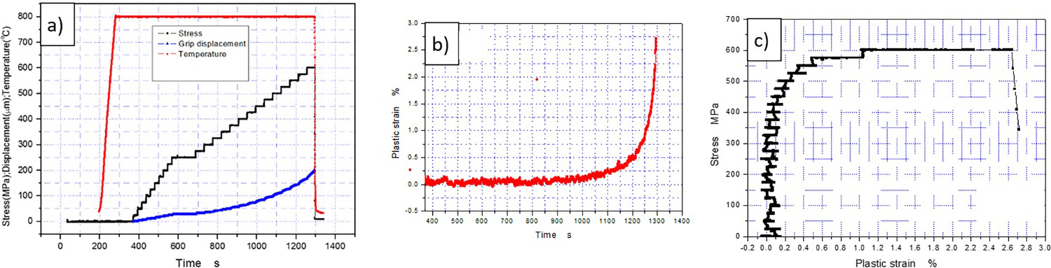
After testing to failure, one half of each sample was mounted and polished by conventional mechanical metallographic processes, finishing with a broad argon ion polish [Hitachi IM4000]. The as-polished microstructure was examined in a Zeiss Supra 40 SEM and mapped by electron backscatter diffraction (EBSD). The fracture face of the other sample half was also examined in the SEM. A Zeiss Auriga Focused Ion Beam (FIB) SEM was used to prepare cross sectional views perpendicular to the polished surface.
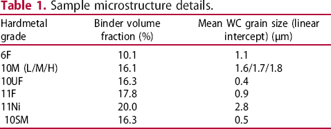
Sample microstructure details.
Results of the microstructural examination are presented first to show the general features observed, before relating these observations to variation in stress–strain curves measured on different samples.
Microstructural examination
The effect of creep on the microstructure of a 6wt-%Co F grade hardmetal is shown in Figure 2 after it had been subject to a final tensile step creep load of 720 N at 800°C (which resulted in a strain of 1.7%). The structure typical of the material before creep can be seen from the example in Figure 2(a,b), taken 2 mm outside of the high-temperature zone, 4 mm away from the creep fracture face at the centre of the sample. Boundaries between the WC grains and between WC and the Co binder are all completely continuous, as expected.
Typical examples of microstructure after creep failure in a 6 wt-% Co F grade, at reducing distances from the final creep fracture. The tensile direction is horizontal. (a, b) 4 mm from fracture (and thus effectively outside the high temperature zone, unaffected by creep), (c, d) 1 mm from fracture, within the high temperature zone and (e, f) 0.25 mm from fracture face. Micron marker bar in 2 (a, c and e) is 1 µm; the location of the enlargements in 2 (b, d and f) is shown by the box in the corresponding lower magnification image. Arrows indicate features discussed in the text.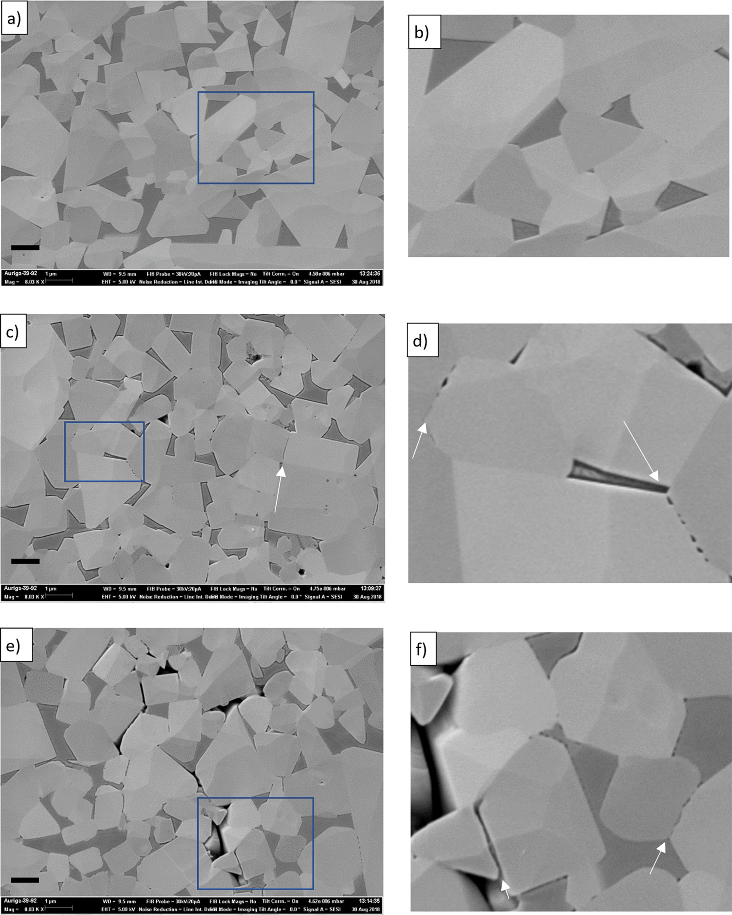
At a distance of 1 mm from the creep fracture (Figure 2(c,d)), which would be within 5°C of the peak temperature, there is a clear change at a number of the WC-WC boundaries. Figure 2(d) shows examples at high magnification, at top left and bottom right, of the formation of a series of small rounded features in a line along the WC-WC boundaries. Less frequent were continuous gaps, an example of which is arrowed in Figure 2(c). Although it cannot be determined from these images, it will be shown later that both the small individual features (described in the following as precipitates) and continuous gaps (lamellae) are not voids but are filled by the Co binder phase.
These features were also visible very close to the fracture (Figure 2(e,f)), perhaps with an increase in the thickness of the Co precipitates and lamellae. What is more noticeable is the increase in number of what are clearly voids, between WC grains and at WC-Co boundaries, and now extending between multiple WC grains. A few small voids are visible in Figure 2(c), confined close to triple points of WC-WC and binder, but in Figure 2(e) these become more frequent and much larger, extending between multiple WC grains.
Figure 3 shows that the formation of precipitates, lamellae and voids are common across a range of WC grain sizes and Co binder phase fractions. The previous example was from a 6wt-% Co F grade: Figure 3 shows examples in 10 or 11wt-% Co binders from both coarser (10M, Figure 3(a,b)) and finer grade (11F and 10UF), Figure 3(c,d) materials.
Voids and Co precipitates or lamellae observed in three Co binder hardmetal grades (a, b) 10M, (c) 11F and (d) 10UF. Arrows indicate grain boundary penetration by the binder phase.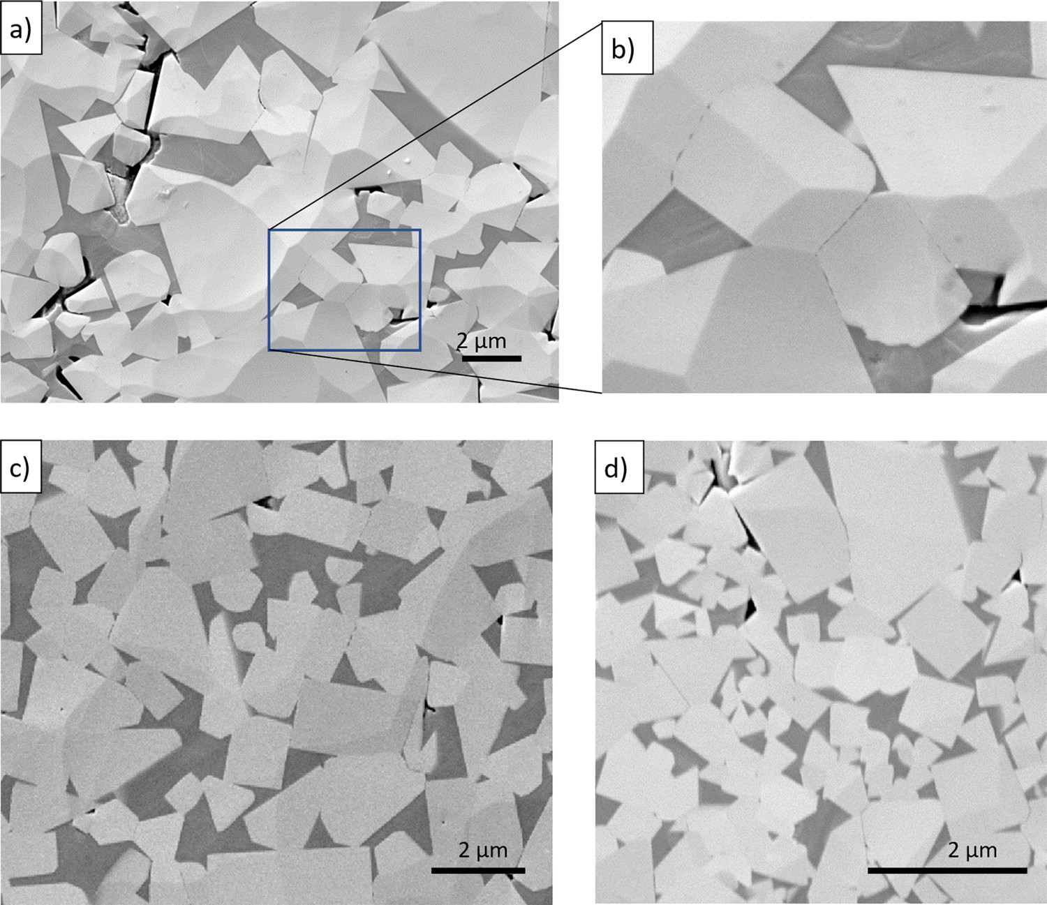
The previous views are clearly 2D sections but by use of the FIB a section perpendicular to the polished surface of the 6F sample was milled close to the fracture face. By milling of 100 nm slices and imaging each new face revealed, a 3D understanding could be built up of the structure. The FIB section also produced a very planar surface and, coupled with high magnification imaging, showed clearly that the features at the WC boundaries were Co. This is seen in Figure 4, in which representative images are shown after removal of approximately 500 nm (or every 5 slices) of material which enables tracking of features at a WC-WC boundary across the width and depth of the boundary. An example WC-WC grain boundary towards the top of Figure 4(a–e) is arrowed and is best described by working backwards from Figure 4(e). Initially (Figure 4(e)) a thin continuous band of Co (lamella) extends across the small contact between the grains. This continuous band is still present when there is much greater contact between grains (Figure 4(d)) but is of variable thickness.
(a–f) Series of cross sections milled by FIB in the 6F grade from the top surface of the sample shown here on the left of the figures (tensile direction is vertical, along the long edge of each image).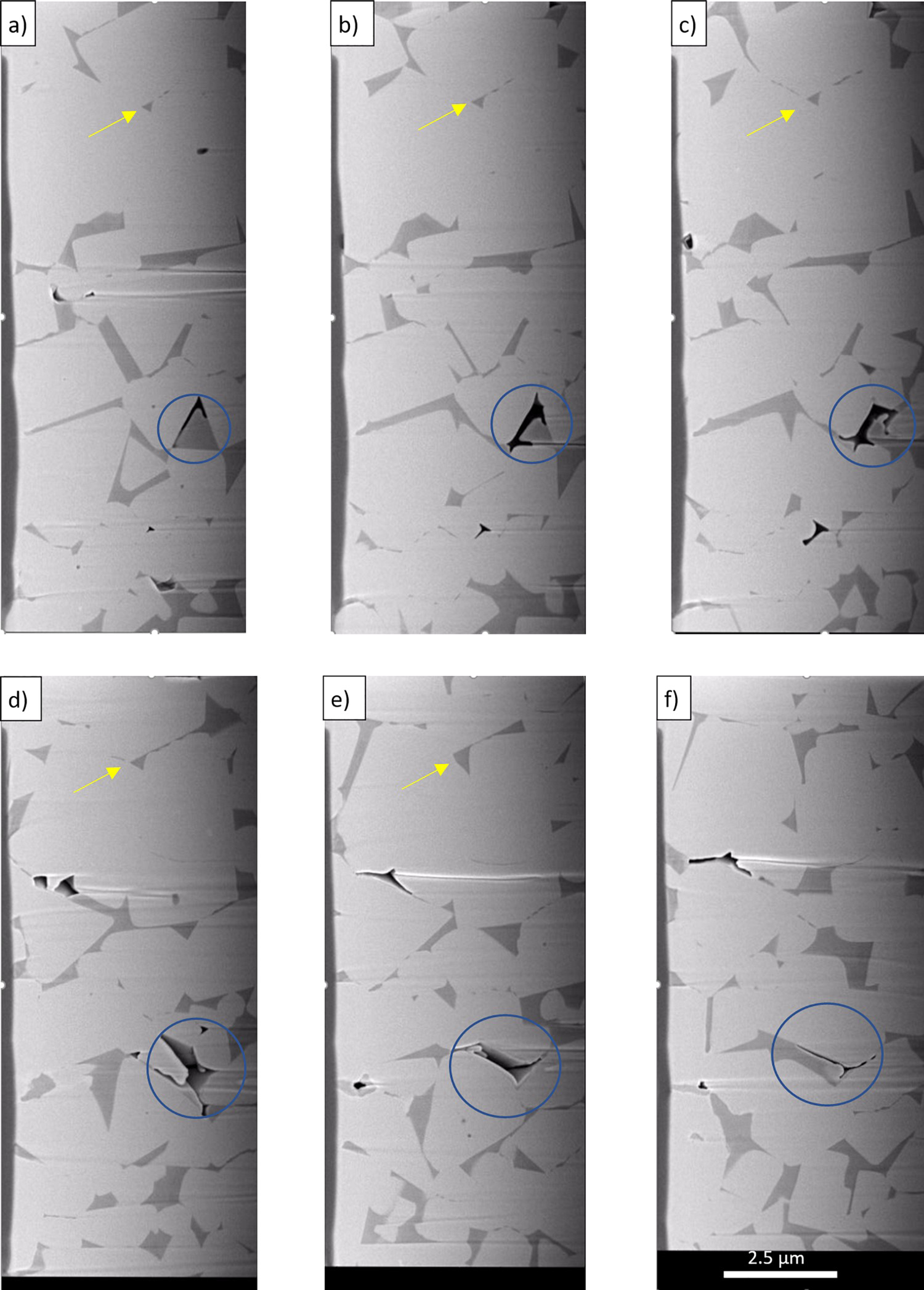
After even more milling, further still along the boundary, the Co only exists in isolated pockets or precipitates, and these become smaller and clustered nearer one end of the WC-WC boundary as the sections progress further into the material. One side of the boundary always appears straight, while the other side is irregular from the Co features extending into the WC grain.
It may be noted that in the above example, as at other similar sites, the Co features are not associated with voids. The voids are often seen as small narrow gaps occurring at WC-Co boundaries, as for example the feature ringed in Figure 4(a). This void increases in size, apparently at the expense of the Co binder phase, until it extends between a number of WC grains (Figure 4(d)) before shrinking again to lie again mostly on a WC-Co boundary.
Figure 5 shows images of the creep failure fracture face of the 6F grade which add to the three-dimensional understanding of the Co distribution between WC grains, even though only one WC grain is visible. In addition to the expected necking of Co typical of monotonic fracture of WC-Co, in Figure 5(a), small features appear dotted across several WC grain facets. In some cases these features are densely packed (to the left of ‘1’), and in others more widely separated (at ‘2’). To the right of ‘1’ and at ‘3’ the WC facets are not completely covered, and while it is difficult to interpret the contrast with certainty, the features appear in recesses (unlike at ‘2’ where they sit on a flat surface. The features in Figure 5(a) are all randomly distributed, but the large facet shown in Figure 5(b) clearly has elongated features in ordered rows.
SEM images of two sites on the creep fracture face of the 6F sample seen in Figure 2. (a) small islands or precipitates of Co seen at random positions on faces of WC grains (see text for explanation of numbers), (b) aligned islands of Co on one WC grain face.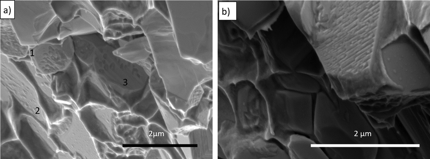
Finally, Figure 6 shows that a 10% Ni binder phase shows very similar behaviour to the Co samples. In the polished face of Figure 6(a), taken close to the creep fracture face, binder phase penetration of WC-WC boundaries is clearly visible, as are voids, although in the area imaged these are present at possibly more of a mix of WC-WC and WC-Ni boundaries. Figure 6(b) shows the creep fracture face of this alloy and again one WC facet is clearly covered in discrete features formed by the binder phase.
Ni binder phase sample. (a) polished section close to fracture face (tension horizontal) with lamealle (black arrows), precipitate (white arrows) and cracks/voids visible at WC-Ni and along WC-WC boundaries. (b) fracture face showing densely packed precipitates, aligned, on one facet.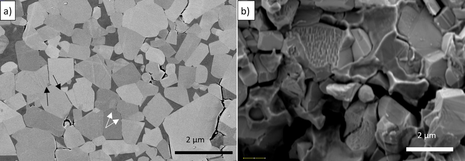
Figure 7 shows a high-resolution SEM image of the 10M grade after creep testing which, when inspected at higher magnification, enabled the identification of all the grain boundaries showing penetration by Co.
10M grade with grain boundaries penetrated by Co ringed in black. Example boundaries close to perpendicular to stress with no Co penetration ringed in white.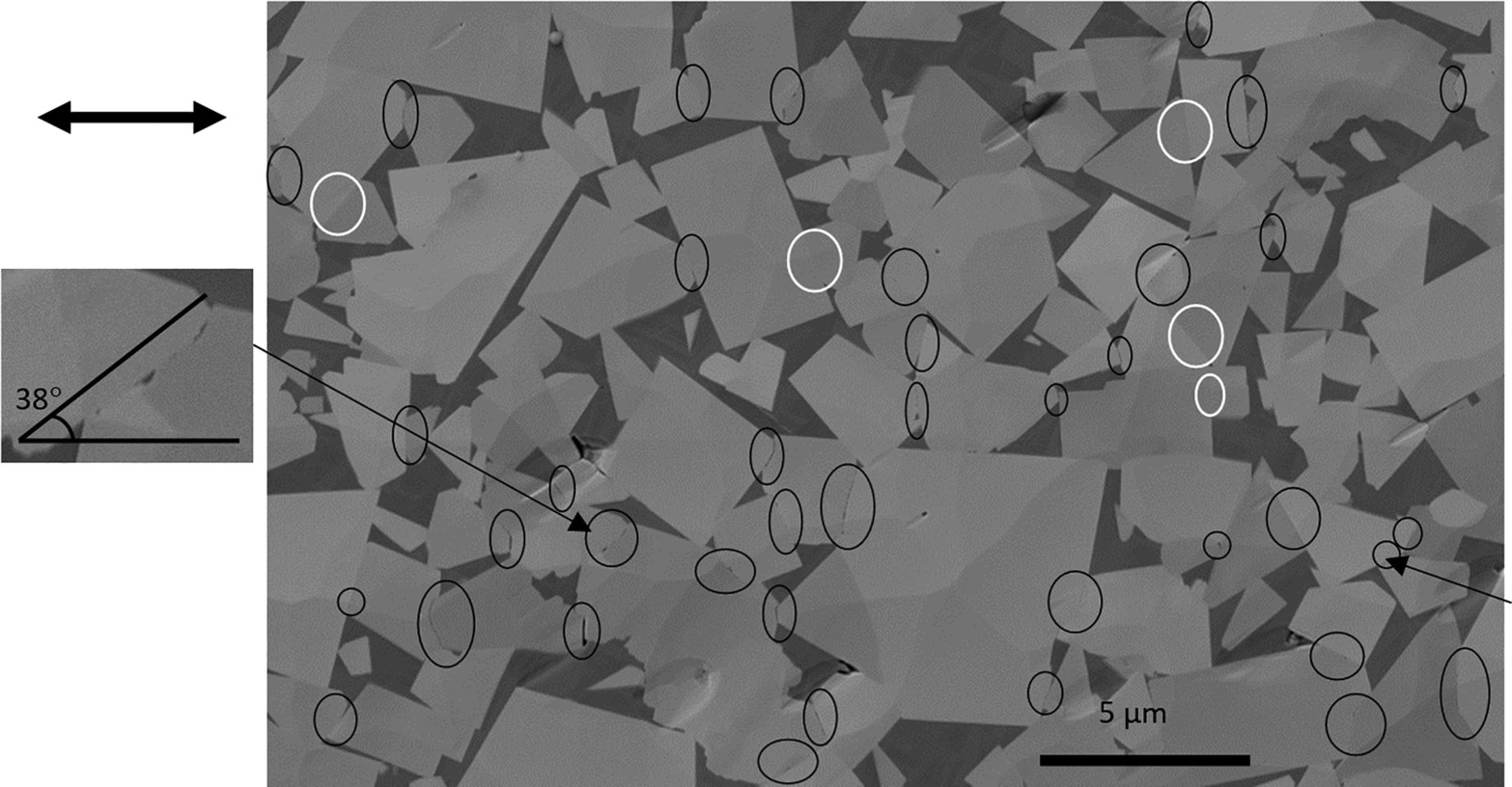
It was observed that the smallest angle between the penetrated boundaries and the tensile direction (horizontal in the image) was 38° so there was a clear tendency for these boundaries to tend towards perpendicular to the applied stress. However, some of these perpendicular boundaries did not show Co penetration. These are identified by a white ring in Figure 7, and matching these to the grain orientations revealed by the EBSD map of the same area in Figure 8, shows that several of these boundaries had prism-prism, basal-basal or prism-basal plane orientation relationships.
EBSD map of area in Figure 7. (a) shows a cluster of slightly misoriented grains, with Co penetration between grains. (b–d) show example boundaries with no Co penetration and with orientations close to basal-prism, prism-prism and basal-basal.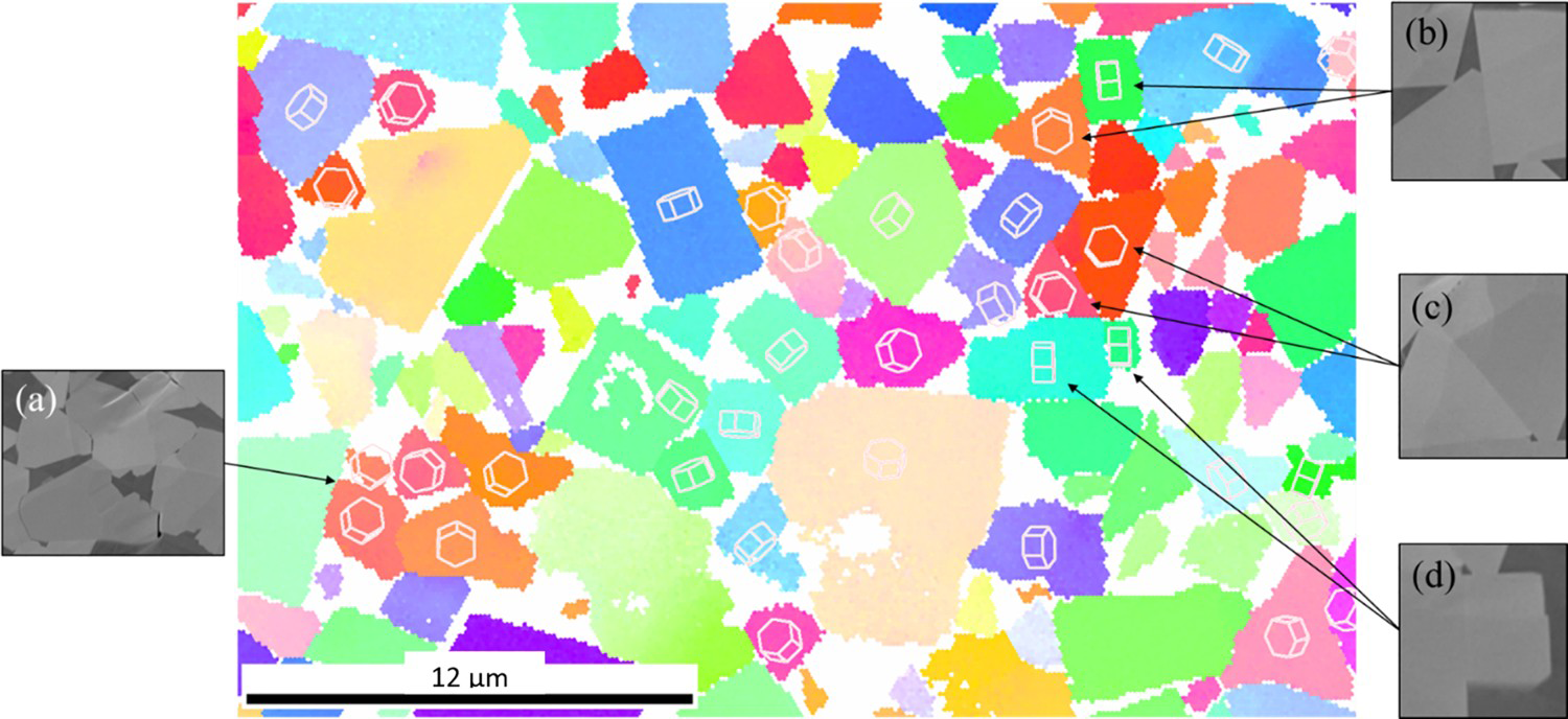
Having established some of the basic microstructural features of creep which appear common to a wide range of hardmetal grades, the following section makes comparisons between similar grades to see if small variations can account for the difference in observed mechanical behaviour. Figure 9 shows stress–strain creep curves for the three carbon ladder samples of the 10 M grade, acquired at both 800 and 900°C. At the higher temperature there is an obvious trend of increasing resistance to creep with decreasing carbon content. The medium carbon grade sample did not then follow this trend at 800°C but the difference between low and high is repeated with the high carbon sample showing, at both temperatures, a greater tendency to deform at lower stresses during stage II creep as well as failing at a lower overall stress in stage III. Higher carbon contents reduce the liquidus temperature of the binder phase, so it is possible that the reduction in strength of the high carbon samples is at least in part due to being tested at a higher homologous temperature.
Creep curves for low, medium and high carbon binder phase samples (L, M, H) 10 M grade samples, for (a) 800°C and (b) 900°C. (lower case letters in graph legend refer to specific sample.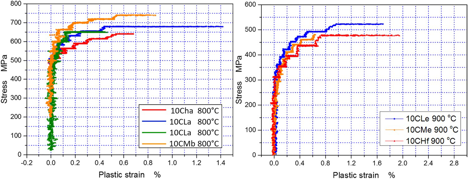
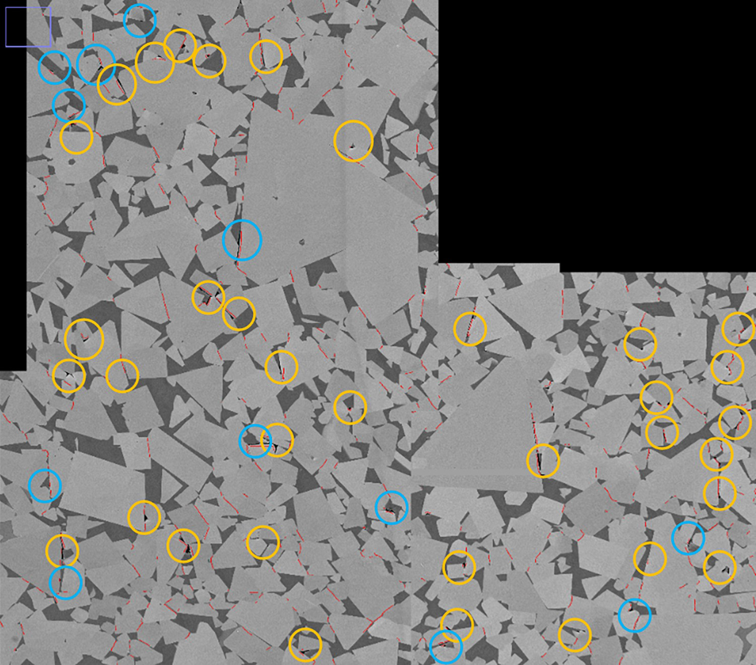
Figures 10 and 11 show high-resolution images of large areas of the low and high carbon 800°C samples, respectively. These were acquired by stitching together smaller images with a 5 nm pixel size to give total areas of ≈ 60 × 60 µm and several thousand grain boundaries to inspect at resolutions similar to that shown in Figure 2. While not visible at the resolution reproduced in the figures, close inspection shows that, as might be expected from the previous results, large numbers of boundaries show Co penetration as lamellae or discrete islands in both samples, the majority perpendicular to the stress axis. Where there is a significant difference between the two samples is, however, in the voids formed at WC boundaries. In the high carbon sample, at least 47 examples of voids can be found, but more than 60% fewer are seen in the low carbon sample; in the low carbon sample, most form between WC grains, particularly at triple points between multiple WC grains. By contrast about 25% of the voids in the high carbon sample form along WC-Co boundaries. Whether these differences are an effect of testing the high carbon samples at a higher homologous temperature or other changes to properties of the binder phase or interface strengths needs further investigation.
Low carbon 10M grade with 21 voids ringed. 3 WC-Co boundary voids ringed in blue. Red lines show Co penetration. High carbon 10M grade with 47 voids ringed. 12 WC-Co boundary voids ringed in blue. Red lines show Co penetration.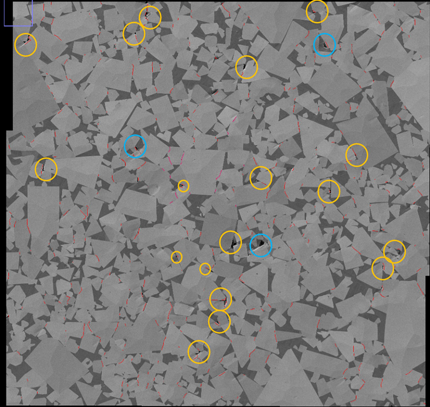
In relating the microstructural behaviour observed here to possible mechanisms for creep, it must be noted that the fracture face and regions close to it will show features of both secondary and tertiary creep under tensile loading. The key features observed in this work are the penetration of Co on WC-WC grain boundaries and the formation of porosity, often at WC-Co boundaries. Both features have been observed before; Co penetration [2–5] and porosity or grain boundary decohesion in [2,3], the latter clearly under compression and secondary creep but in three point bending and turning studies [4–6] the stress state and creep stage is less clear cut. Most reports of property measurement concentrate on the steady state secondary creep and discussion of mechanisms also assumes this stage.
However, the following examples from a 10SM grade, in which one sample was strained to failure (tertiary creep) and a second halted after secondary creep before failure, suggests that valid comparisons can be made with earlier work: both samples, tested at 900 °C show the same features of voids and grain boundary penetration already described even though the first had only been tested to the late secondary stage. The similarity of the strain applied to these two samples before the tertiary creep stage is seen in Figure 12. The lower curve shows strain against time for the interrupted test sample for which loading was removed after ≈0.65% strain produced by a stress of 450 MPa. The upper curve shows an identical sample which was initially strained at 400 MPa before increasing to 450 MPa and allowing continued strain into the tertiary creep regime until failure at about 1% strain.
10SM samples strained to failure (black, upper curve) and interrupted after only secondary creep (green lower curve).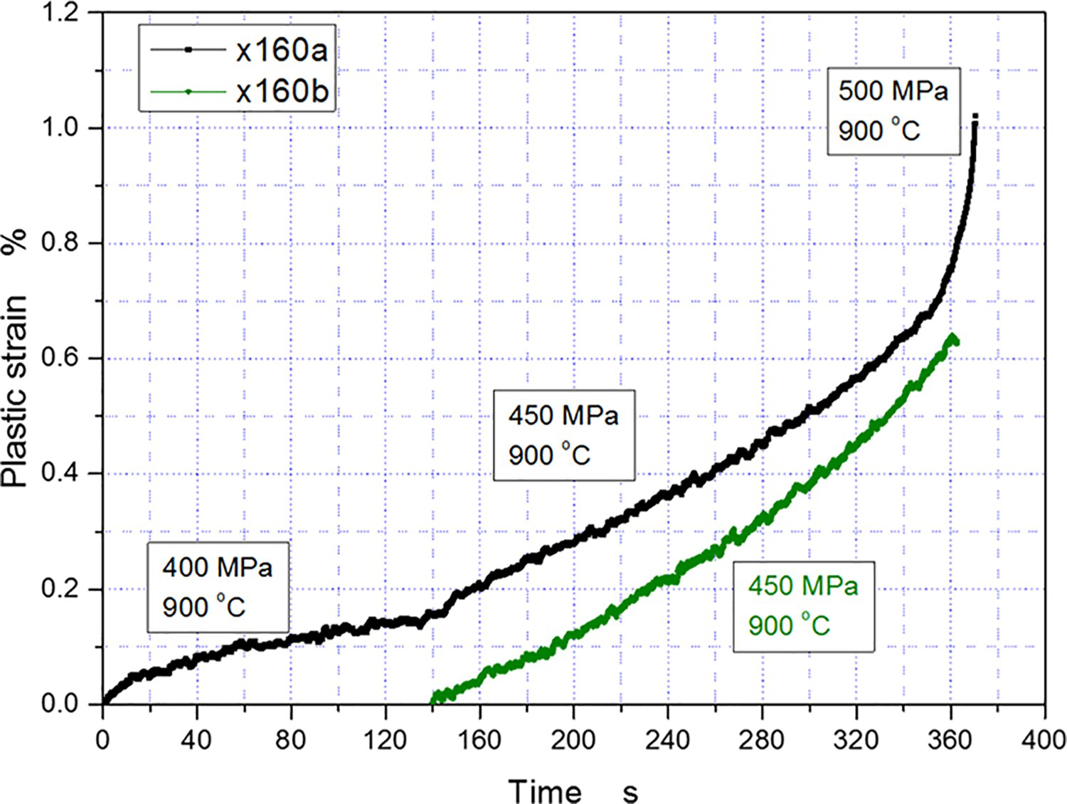
The images in Figure 13 show that voids (Figure 13(a,b)) and Co penetration (Figure 13(c,d)) are seen in both (the fractured and interrupted test) samples with a similar appearance to these features shown in the previous figures from other fractured samples. The density of voids in the interrupted test is lower than in the fractured sample, just as it is at a distance of a few millimetres from the fracture of the failed specimen. From the similarity of the features seen after secondary and tertiary creep, it would seem reasonable to conclude that comments on the mechanisms suggested by the failed samples described in the results are still relevant to a general discussion of creep in the context of earlier reported observations.
Secondary electron image (a) of tertiary creep 10SM sample strained to failure and (b) of secondary creep 10SM sample at an equivalent (central) position to that of (a). (c, d) Backscatter electron images showing Co precipitation between WC grains.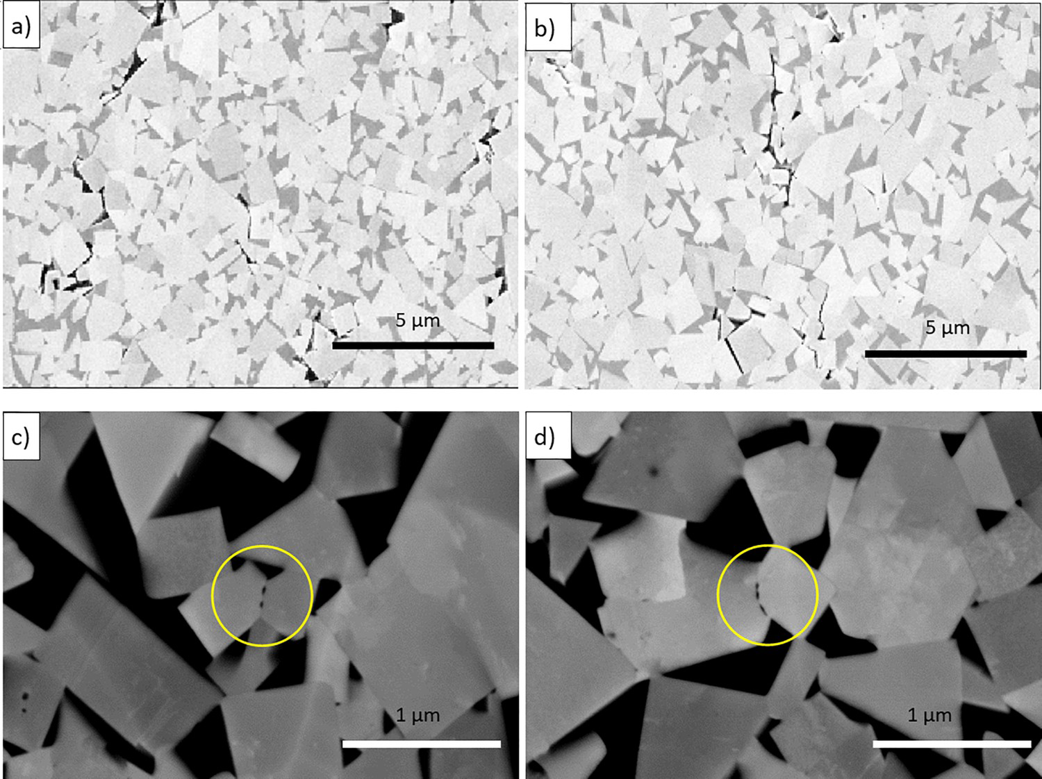
Void or porosity formation leading to failure is a common feature in tertiary stage creep of metals. From the 2D images shown in this paper, it might be possible to conclude that some voids form at Co-WC boundaries (e.g. top right of Figure 2(d), Figure 3(b,a)) while other more crack-like voids at WC-WC boundaries or triple points. The latter would be consistent with the W-type wedge-shaped crack formation mechanism when sliding on some grain boundaries interacts with a non-deforming or static grain [10]. However, the 3D interpretation possible from the sequence in Figure 4 suggests that narrow cracks at WC-WC boundaries are linked to larger voids formed at WC-Co boundaries. The size and morphology of the voids at the WC-Co boundaries would seem to rule out the suggestion [3] of intergranular cavities arising from unaccommodated grain boundary sliding. The alternative explanation is the significant diffusion of vacancies, along grain boundaries, and possibly generated by grain boundary sliding. Vacancy diffusion implies the mass transport of Co in the opposite direction.
Indeed the penetration of Co between WC grains must clearly be by diffusion, with an additional driving force of the applied stress since penetration was only observed on boundaries closer to perpendicular to the tensile axis and thus more likely to be ‘opened’ by the applied stress. Uniform thickness lamellae of Co have been seen in both SEM and TEM samples from compression [2,3] and machining samples [4,5]. However, the predominant observation in the current case is of separate pockets or precipitates of Co along the length of a boundary, with a tendency to bulge into one grain only while leaving a flat facet on the other, which matches with the TEM observation of [5]. The fracture face observations suggest these precipitates can be either randomly arranged in small islands or elongated and aligned with one another.
The implication of the precipitate morphology is that the grain boundary habit planes are probably important in controlling the pattern of Co precipitates. Ostberg and Andren [5] show an example where the flat face was a prism plane and in one case the development of new facets on the bulge faces. The EBSD mapping in Figure 8 was not carried out with the resolution that would be needed to look at the facet formation of the bulges, but analysis of the orientation of the flat face is possible. Of the 41 boundaries identified with lamellae in Figure 7, 13 could be positively identified as having a flat face with bulges into the other grain and of these, 7 had a prism plane parallel to the flat facet, 3 a basal plane and 3 no obvious alignment with any plane. Of the remaining infiltrated boundaries, most were not resolved clearly enough in the SEM image to determine if one face remained flat. A few lamellae were neither parallel-sided or flat/bulging and indeed were curved. The observations from the EBSD map of some boundaries that have not been penetrated with a possible CSL2 tilt or twist type orientation between the grains is in agreement with several other observations [1,4].
Ostberg and Andren suggest boundary infiltration is stress assisted dissolution. In the current case, the majority of the infiltrated boundaries were suitably oriented, nearer to perpendicular than parallel to the tensile axis, but the discontinuous Co suggests that both diffusion between WC-WC boundaries with some dissolution at specific points on the boundaries. Diffusion of Co along WC-WC boundaries away from the main Co skeleton (and thus vacancy diffusion in the opposite direction) might be expected to account for some of the void formation seen, but it will be noted that precipitates arrowed in Figure 4 are not associated with voids at adjacent interfaces.
The Co penetration has been suggested to be a necessary precursor to grain boundary sliding, but in this stress state, only a few of these penetrated boundaries have much alignment with the tensile axis so this does pose the question of what mechanisms are enabling creep in the current work. The temperature of the tests is only 800°C which is much lower than that in [1–3] and based on the summary by Mari [11], this is below the temperature at which grain boundary sliding (and certainly any WC deformation) would be possible.
At this temperature, Mari suggests deformation of the binder phase will be responsible. The image contrast seen in the binder phase in Figure 14 (an enlargement from Figure 7) supports this mechanism, with the binder phase that was largely FCC before creep now showing multiple slip bands visible, indexed in many cases as the HCP phase by EBSD. Some caution is needed with the interpretation as binder phase transformation does occur on cooling from creep, and comparative studies on non-crept samples would be needed to see if the creep stress induces more HCP phase or HCP with a different morphology than simple cooling of an unstressed sample.
Contrast variation in Co binder (cross hatched bright and dark bands) of 10M grade showing hcp formation in what was uniform contrast at room temperature from nearly fully fcc binder, resulting from deformation at 800°C during creep.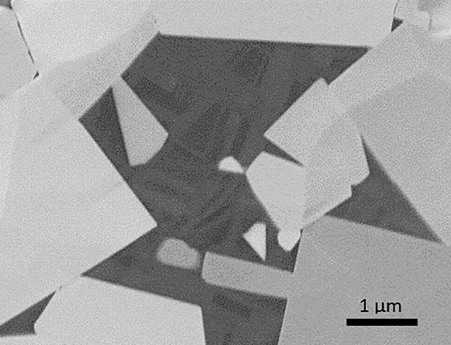
Some of the creep could be accounted for by void formation, but the voids make up <0.5% by area so substantially more of typically 1–1.5% strain must be accounted for. The lamellae formation could just result from dissolution of the WC grains, but the examples in Figure 15 suggest some grain boundary sliding with the lamellae then accounting for some of the strain. While the void formation cannot account for the full strain it is probably significant that the number of voids increases with the increasing carbon content of the binder phase.
Examples of Co penetration in tensile creep at 800°C between irregular WC-WC boundaries which suggest some grain boundary sliding may occur.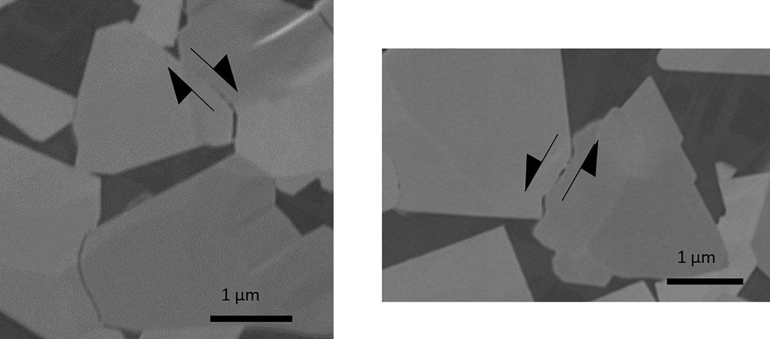
Tensile creep behaviour of a range of hardmetal grades has been studied between 800 and 900°C. This temperature is low relative to many previous microstructural studies carried out at 1000°C or more. Despite this, similar characteristic features have been observed in the final microstructure:
Co penetration along grain boundaries, most commonly as multiple discrete precipitates rather than the straight lamellae previously reported Voids which, when considered as 3D features, are generally largest at WC-Co interfaces, narrowing to smaller cracks at WC-WC interfaces
The Co precipitate structure is frequently related to the boundary orientations of the two WC grains between which they form. They appear to grow into grains with random boundary orientations and not into those with basal or prism habit planes.
Void formation is difficult to explain as (a) they appear large relative to the likely flux of vacancies from WC-WC boundaries (and are not always near WC-∼WC boundaries with precipitates) and (b) do not appear to form by wedging open by rigid WC skeletons.
The same features are observed in grain sizes ranging from 0.4 to 2.8 µm and binder phase fractions of 6–11wt-%, and also in samples with a Ni binder phase. Evidence of binder phase deformation has been observed in a Co containing material, but void formation and grain boundary sliding may also be occurring despite the relatively low creep temperature. Despite the similar mechanisms observed, the carbon content of the Co binder phase was shown to have a significant effect on the creep strength, with high carbon contents failing at lower stresses.
Footnotes
Acknowledgements
Funding by Hilti, Sandvik and Ceratizit and from the National Measurement System of the UK Government Department for Business, Energy and Industrial Strategy is gratefully acknowledged. Members of the British Hardmetals Research Group are thanked for the provision of samples.
Disclosure statement
No potential conflict of interest was reported by the author(s).