
Abstract
In this study, powder metallurgical steel samples containing 1.5% C by weight were produced by sintering in a vacuum atmosphere at 1200°C. The impact test and dry sliding wear test specimens were prepared in accordance with ISO 5754 and ASTM G-99 standards, respectively. The wear and impact toughness properties of spherical cementite in the bainitic matrix (SCBM) microstructured specimens produced with different heat treatment routes were compared with pearlite plus primary cementite, fully tempered martensitic, fully bainitic and spherical cementite microstructured specimens in ferritic matrix (SCFM). Microstructural characterisations of all specimens were performed by SEM, EBSD and XRD analyses methods. Compared to fully tempered martensitic and fully bainitic microstructured specimens with similar hardness, both the dry sliding wear and the impact toughness properties of the specimens having SCBM microstructures were improved with the increased austempering time after spheroidisation treatment.
Highlights
Spherical cementites in the bainitic matrix (SCBM) microstructures were achieved by heat treatment cycles in high carbon powder metallurgy steels. The wear and impact toughness properties of SCBM microstructures compared with fully bainitic, tempered martensitic and spherical cementite in the ferritic matrix microstructures. Both the wear and impact toughness resistance of SCBM samples were much better than other microstructures at an unprecedented rate in history.
Introduction
Many properties of functional materials prepared for the purpose are developed with their microstructure. In fact, material science engineering is also a kind of microstructure designer. The properties can be improved by controlling the type, amount and morphology of the secondary phase formed by the alloying elements added in the metals and their alloys. Various analyses and modelling can be made according to the material texture [1–4]. Powder metallurgical (P/M) sintered parts are readily used as precision parts in many industrial sectors, especially in engines and transmission [5–7]. In order to provide high mechanical properties in P/M components used in automotive industry, especially in power transmission parts and bearing materials, it sometimes requires a heat treatment [8,9]. The use of steels with their perfect combination of high strength and impact toughness constitutes the main goals of the steel material industry [10–12].
Quenching plus tempering, austempering and spheroidisation heat treatments are widely used to improve the mechanical properties of steels [13–19]. Two types of spheroidisation annealing are often used; the first, subcritical spheroidisation below the Ac1 temperature, which is mainly applied for hypoeutectoid steels. During subcritical annealing of steels with an initial pearlite structure, the cementite lamellae break up into spheroids driven by the reduction in surface energy. The second treatment, the intercritical spheroidisation above the Ac1 temperature, which is mainly applied for hypereutectoid steels in order to spheroidise and partially dissolve the grain boundary cementite. However, spheroidisation of primary and secondary cementite phases takes quite a long time. Therefore, by overtempering of the steels with martensitic microstructure, spheroidisation of cementite particles can be achieved [16,17,20,21].
Austempering is a high-performance isothermal heat treatment which can impart superior performance to ferrous metals [22]. Many researchers have suggested that the isothermal heat treatment significantly improves the mechanical properties of materials such as the toughness, strength, and wear resistance, since it produces the bainitic microstructure [23,24]. The austempering process offers advantages over quenching and tempering for many engineering applications [25,26].
While hard cementite phases provide wear resistance in the high carbon steels, they should not be broken against the applied loads. Therefore, the spheroidisation heat treatment can be carried out. On the other hand, it is known that bainitic structures produced by austempering heat treatment provide high toughness properties. In the present study, it was aimed to improve both the toughness and wear properties of hypereutectoid P/M steels with the combination of hard secondary phase cementite particles and the main bainitic structure.
Material and methods
In this study, 1.5% by weight of powder graphite (Alfa Aesar 99.9% purity, 200 mesh average particle size) was added to water atomised pure iron powders (Atomet 1001, 99.99% purity, 60 μm average particle size) as a carbon source. The prepared mixture was added to the powders with 0.5% Zn stearate as a lubricant and compacted at room temperature under 700 MPa pressing pressure. The Charpy impact and the wear test specimens were produced in accordance with ISO 5754 and ASTM G99 standards, respectively. Sintering of the specimens was carried out by keeping them in a vacuum atmosphere of 5 × 10⁻² Pa at 1200°C for 20 min. By the calculations according to Archimedes density measurement method, the specimens reached an average green density of 6.9 g.cm−3 after cold-pressing, and 7.3 g.cm−3 sintering density after sintering. Thus, a densification ratio of 0.93 was achieved. The combined carbon content of the specimens after sintering was determined as 1.49% by the spectrometer (Q4 TASMAN) chemical analysis method. The sintered specimens are coded as ‘S’.
Some sintered specimens were austenitised at 950°C for 3 min and then austempered for 1 h in a neutral salt bath at 350°C, resulting in fully bainitic microstructures and coded as ‘FBM’. The other sintered specimens were austenitised at 950°C for 3 min, followed by rapid quenching to room temperature, resulting in a fully martensitic phase and tempered at 200°C for 1 h. These samples are coded as ‘TM’. Spherical cementite microstructures were produced in ferritic matrix by tempering TM samples at 705°C for 1–2 h and they depending on the tempering time were coded as ‘SCFM-1’ and ‘SCFM-2’, respectively. Finally, the SCFM-1 and SCFM-2 specimens were partially austenitised for 3 min at 750°C in the region containing the austenite plus primary cementite phases and then spherical cementite (SCBM) microstructures were produced in a bainitic matrix by austempering for 1–2–5 h in a salt bath at 350°C. At the end of this process, the specimens were coded as SCBM 1-1, SCBM 1-2, SCBM 1-5, SCBM 2-1, SCBM 2-2, SCBM 2-5, depending on the austempering time for 1,2,5 h of SCFM-1 and SCFM-2 specimens. A schematically summary of all these processes is shown in Figure 1.
Schematically heat treatment cycle graphics for processing of the SCBM specimens.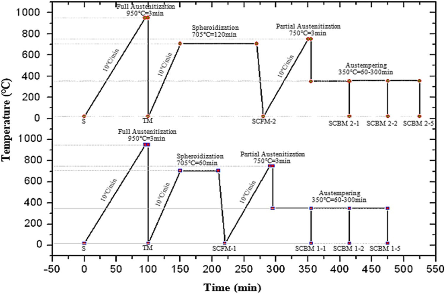
In order to achieve the microstructures, conventional metallography processes were applied to all specimens and they were etched with 4% nital solution. The obtained microstructure imaging and fracture surface examinations were carried out with the JEOL JSM-6060LV Scanning Electron Microscopy (SEM). The macro- and micro- hardness values of the specimens were determined by Shimadzu hardness tester device as HV1 and HV0.1 Vickers.
Orientation of the main and precipitated phases, grain boundary angles and average grain size were determined with Philips-FEI Quanta 400F brand electron back scattered diffraction (EBSD) device. For EBSD analysis, the specimens were polished with 0.2 μm fumed silica and finally 0.05 μm colloidal silica after the final polishing process and cleaned for 20 min in an ultrasonic cleaner. In EBSD analysis performed with a device of 20 kV voltage, a working distance of 15 mm was used in an area of 40 × 40 μm2 at each scanning distance.
X-ray diffraction (XRD) analysis was performed with Bruker D8 Advanced device using CuKα (λ = 0.154 nm) target and step size 0.06°/s in order to detect Fe3C and other possible carbide phases precipitated after heat treatment.
Dry sliding wear tests of the specimens produced according to ASTM G99 were carried out under constant 10 N load, 2.5 m.s−1 sliding speed and 1500 m wear distance using pin-on-disc method in UTS TRIBOMETER T10/20 wear test device. The specific wear coefficient (K) of the specimens was calculated using the Archard method [27].
The tests of Charpy impact specimens prepared according to ISO 5754 standard were carried out at room temperature in an Instron-Wolpert brand impact test device with a hammer capacity of 150 J (Figure 1).
SEM microstructure images of the samples are given in Figure 2. In Figure 2(a), there are pearlite colonies densely distributed in the ferritic matrix in the microstructure image of the sintered S specimen, which is the initial microstructure for all heat treatment parameters. The microstructure of the dense plate martensite and then tempered in the TM specimen produced by quenching the full austenite region is seen in Figure 2(b). In Figure 2(c,d), the microstructures of the SCFM-1 and SCFM-2 specimens containing spherical cementite are seen in the ferritic matrix obtained by overtempering of the fully martensitic specimens at 705°C for 1–2 h. During martensite annealing, carbide precipitation occurs rapidly [16,17,28]. Figure 2(e) shows the microstructure of the FBM specimen with lower bainitic morphology, kept isothermally at 350°C for 1 h after full austenitisation.
SEM microstructures of (a) S, (b) TM, (c) SCFM-1, (d) SCFM-2 and (e) FBM specimens.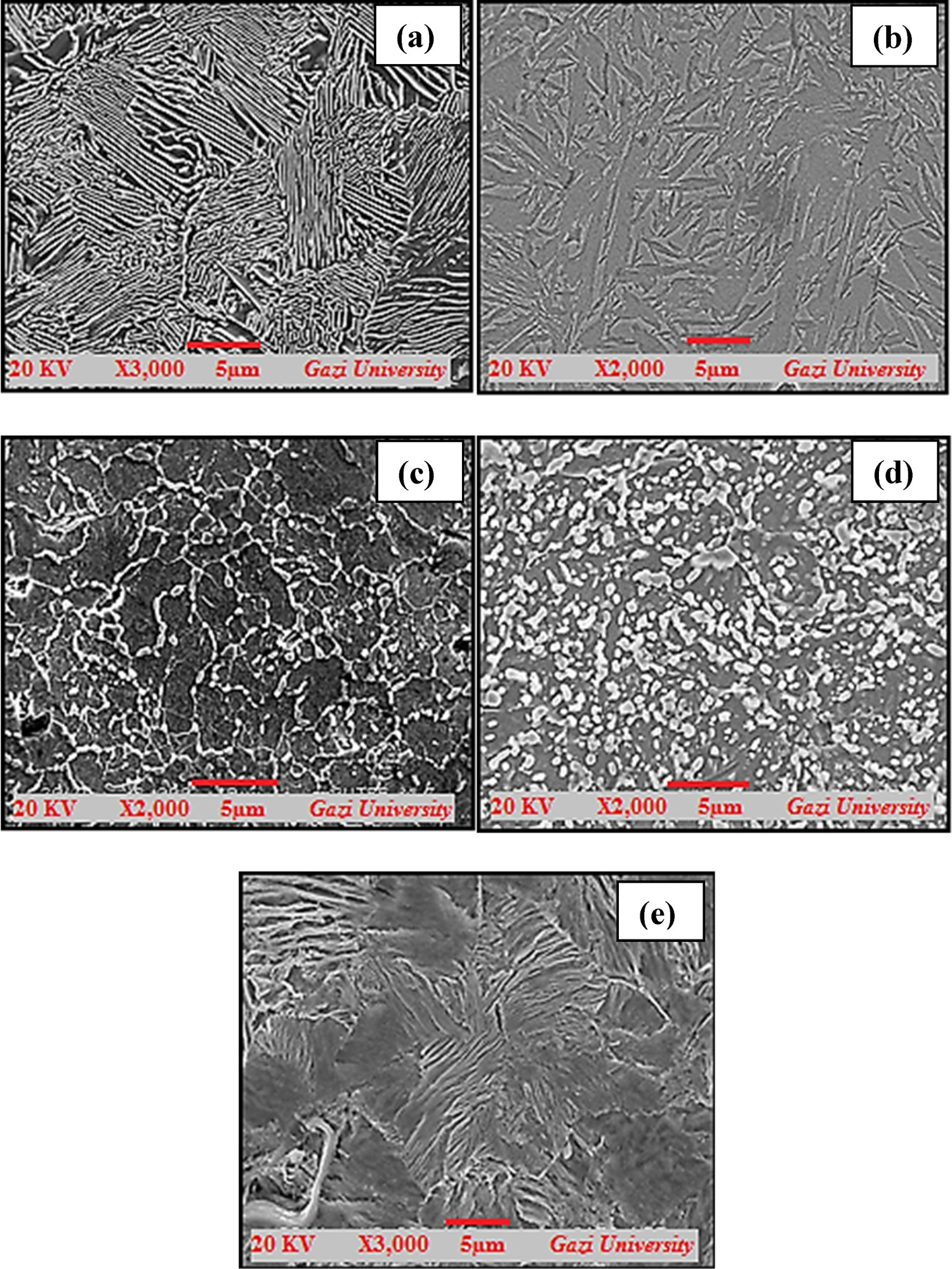
In Figure 3(a–f), microstructures of SCBM specimens containing spherical cementite in bainitic matrix by austempering at 350°C for different periods (1,2,5 h) after the austenite plus spherical cementite phase transformation is completed in SCFM specimens partially austenitised above Ac1 temperature. It is observed that the bainitic areas increase due to the increasing austempering time. Spherical cementite compounds are thought to begin to dissolve in the matrix with increasing austempering time [29]. It is estimated that the spherical cementite obtained by overtempering of martensitic specimens for different periods does not reach equilibrium thermodynamically.
SEM microstructures of (a) SCBM 1-2, (b) SCBM 1-2, (c) SCBM 1-5, (d) SCBM 2-1, (e) SCBM 2-2, (f) SCBM 2-5 specimens.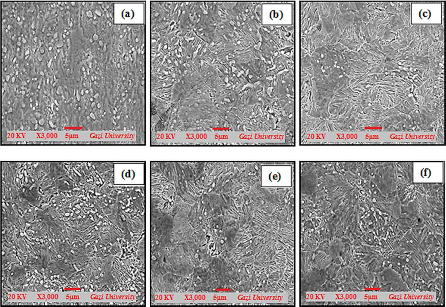
EBSD analysis images of some specimens are given in Figure 4(a–d). According to the EBSD map of the coarse pearlitic S specimen produced after sintering in Figure 4(a), it is understood that the perlite colonies are oriented in almost all habit planes. It can be noted in Figure 4(b) that the areas of larger martensite laths or plates parallel to the specimen surface in the scanned area are oriented in the planes (110) and (100). However, the high dislocation densities within the martensite laths and porosity of the material caused some deterioration in the crystallographic planes in the scanning area.
EBSD images of (a) S, (b) TM, (c) FBM, (c) SCBM 2-5 specimens.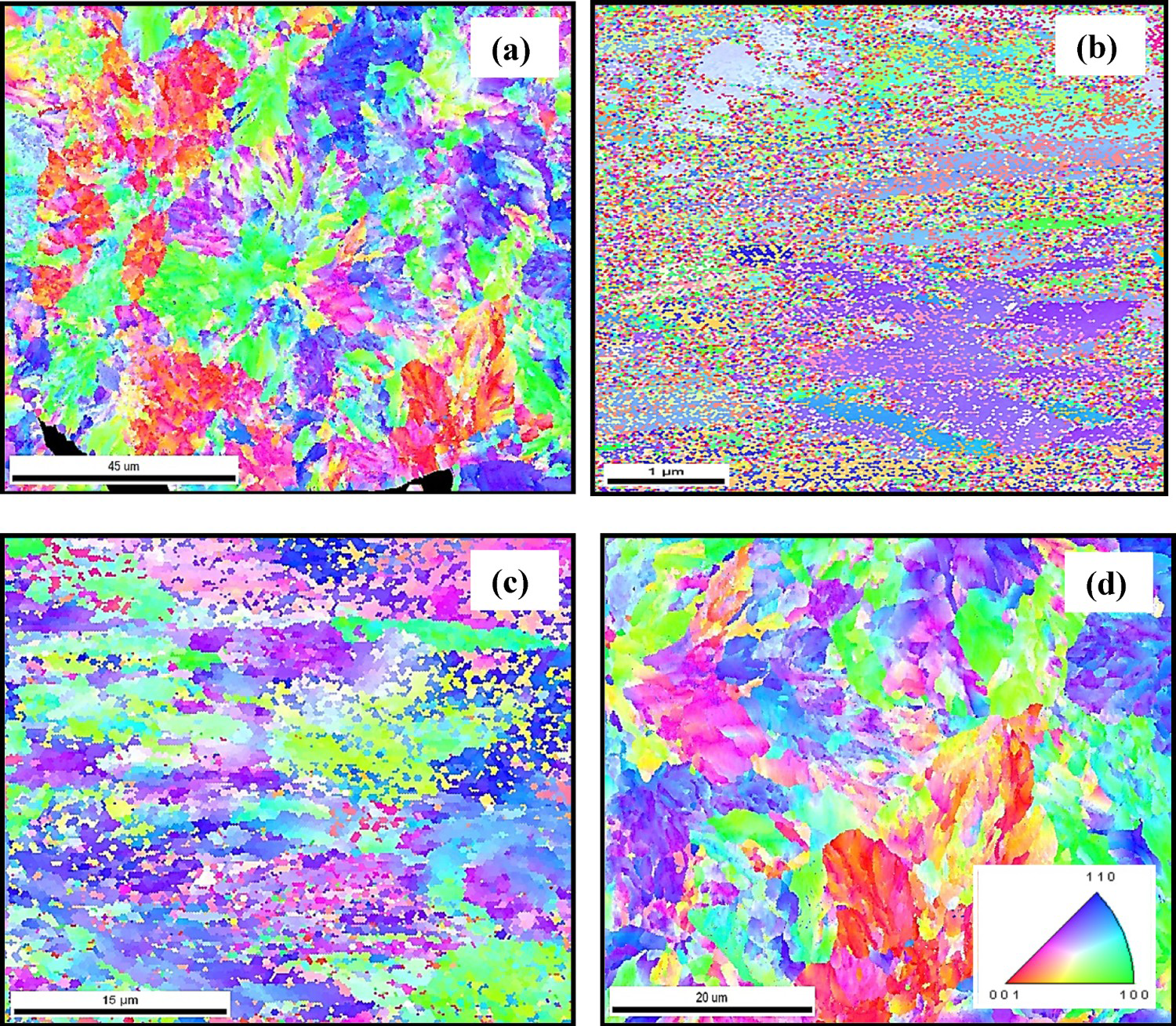
While it was observed that the FBM sample in Figure 4(c) grew partially in the (110) plane, regions with varying crystallographic orientations were revealed on the EBSD map of the obtained bainite microstructure, probably on the austenite grains with the previous 15–20 µm size. These regions are characterised as a complex bainite topography. The size of the carbides formed in bainite is between 1.5 and 5 µm (Figure 4(c)). It is seen that there is no preferential distribution in S and SCBM 2-5 specimens in Figure 4(a,d) [30].
High angle grain boundaries are strong barriers to crack propagation by blocking the crack path or changing direction. This is another influencing factor to consider when discussing impact energy in FBM or SCBM specimens.
The misorientation angles of the specimens are shown in Figure 5. In the FBM and SCBM-2-5 specimens, misorientation angle-number fraction is more than TM sample. In other words, high angle grain boundaries are lower in the bainitic microstructured specimens. The bainitic microstructure can be attributed to increased low-angle boundaries of both FBM and SCBM, an increase in packet and block boundaries as seen Figure 4. The ferrite, which occurs in the formation of bainite from austenite, is thought to be low grain boundary angle in the FBM and SCBM-2-5 specimens. It has been observed that the isothermal annealed samples have higher angle grain boundaries than the tempered sample [31]. While the final bainite structure was produced in FBM and SCBM-2-5 samples, it was isothermal annealed above martensite transformation start (Ms) temperatures. It can be speculated that the metastable austenite phase grains at isothermal temperature of 350°C are high angle before the bainite reaction starts. However, when the bainitic transformation begins, lower misorientation angle in the bainite micro-constituents were observed to be formed.
Misorientation angle-number fraction graphics of (a) TM, (c) FBM, (c) SCBM-2-5 specimens.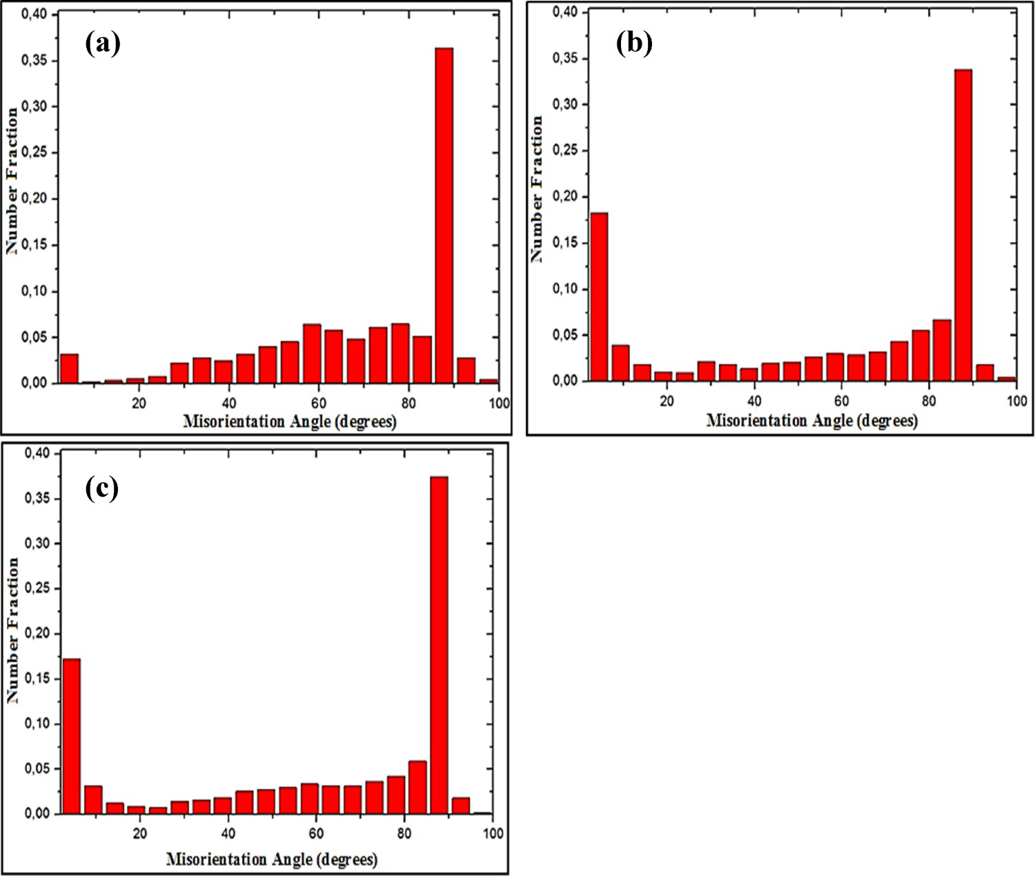
In Figure 6, the type of possible phases formed due to the solid state transformation caused by XRD analysis and some applied heat treatment has been examined. In these studies, it was aimed to determine the retained austenite phase by determining the formation of Fe3C (cementite) and possible transition iron carbide phases depending on the type of heat treatment applied. According to the XRD results of the high carbon S specimen, it contains ferrite and low intensity cementite peaks. It can be said with the help of peaks that the temperature and time applied in the sintering process are sufficient for the formation of phases that are likely to precipitate. The XRD peaks formed as a result of tempering the martensitic sample at 200°C for 1 h, obtained by quenching in a room temperature water bath from full austenitising temperature, are seen. It can be explained by the presence of residual austenite formed in the (220) plane that the structure cannot fully transform into martensite with BCT crystal lattice structure. In addition, ϵ (Fe2C) carbides started to form due to low temperature tempering. The peaks of the FBM sample, which has a complex crystallographic structure, is a mixture of ferrite and non-lamellar cementite kept in a neutral salt bath at 350°C by isothermal annealing from austenitising temperature. Besides the prominent ferrite peaks, cementite peaks and low intensity austenite peak that could not be transformed by isothermal annealing are observed. In the ferritic matrix obtained by overtempering of the martensite phase, it is seen that the peaks of the spherical cementite sample do not contain intermediate carbides such as Hägg and epsilon, which are likely to form until the spherical precipitation of cementite. A high number of cementite peaks are observed in XRD lines of SCBM 2-5 specimen. It can be noted that this situation is caused by both the spheroidal cementite and the bainite. It was determined that the orthorhombic crystal lattice structure of the formed spherical cementites had a, b, c parameters 4.51, 5.04, 6.73 Å, respectively.
XRD lines of the S, TM, FBM, SCFM-2 and SCBM 2-5 specimens.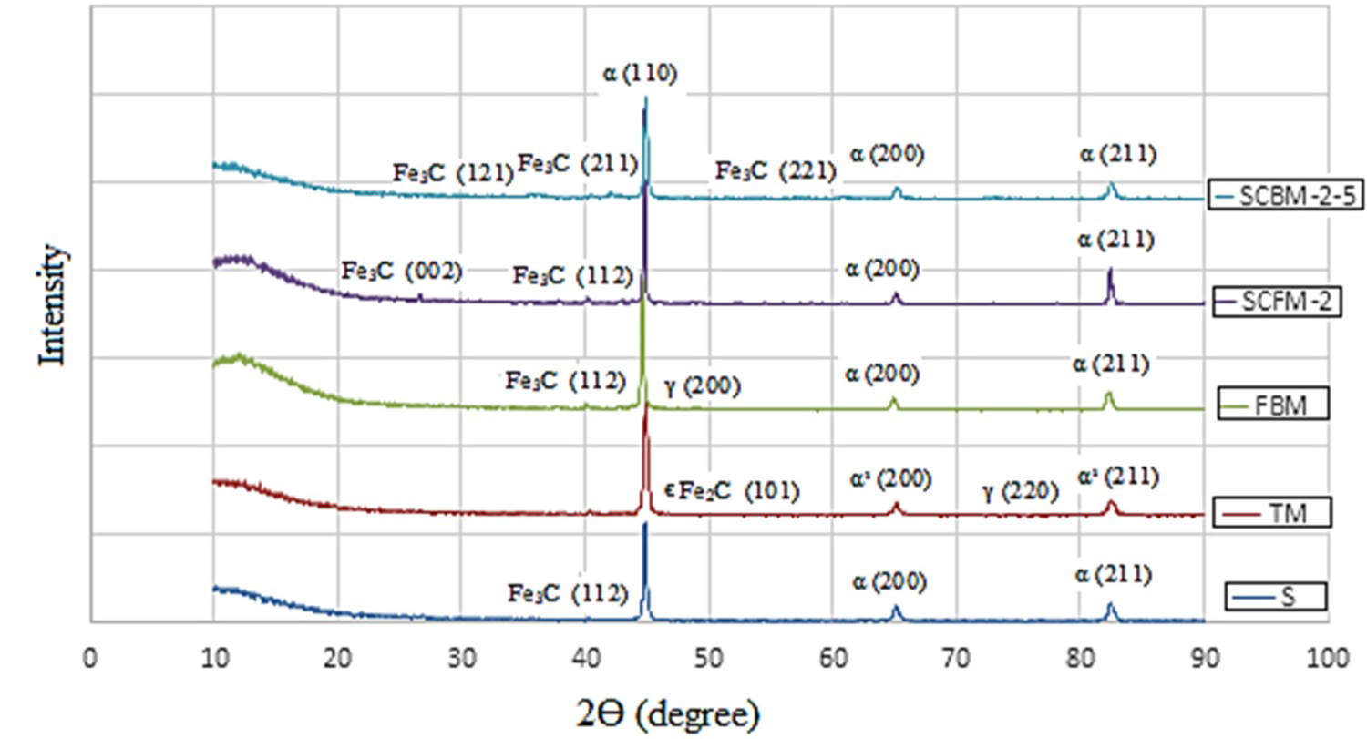
Density values and mechanic properties of the specimens.
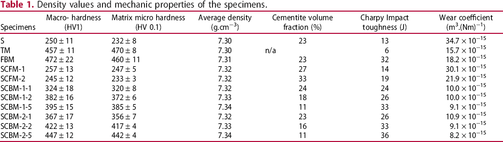
When the macro- and micro- hardness values of the samples are examined in Table 1, it is an expected result that the sintered S specimen has low hardness values and this is due to the formation of pearlite colonies in the soft ferritic matrix. It was aimed to increase the impact toughness by decreasing the hardness as a result of tempering the TM specimen in order to remove its excessive brittleness. Among the heat treated specimens, the hardness values of TM and FBM specimen are close to each other and at the highest level. Although TM specimen has similar wear resistance with similar hardness FBM specimen, their impact toughness values are significantly low since it contains martensitic phase. Although the hardness values of SCFM specimens containing spherical cementite in the ferritic matrix are close to the sintered S specimen, it can be said that both impact toughness and wear values have improved. This is due to the fact that cementite in its microstructure is spherical precipitation instead of lamellar structure. It is known that spherical cementites distributed homogeneously in the matrix are at lower energy level and more stable than lamellar structure [33]. However, SCFM specimens are far behind in terms of hardness, impact toughness and wear coefficients among heat treated specimens.
Mechanical test results of SCBM specimens are presented graphically in Figure 7. It can be said that the mechanical properties of SCBM specimens have increased due to the increasing austempering time. It is seen that SCBM-2 specimen have superior properties compared to SCBM-1 specimen (Table 1). This situation is similar to SCFM specimen, which are the initial microstructure of SCBM specimen. It is seen that the hardness of the SCBM-2 samples in the isothermal holding times increasing from 1 to 5 h is as much as the TM and FBM specimens. With the increase in hardness, it is seen that the impact toughness, especially the wear resistance, increased significantly (Figure 7). The impact toughness values in SCBM 2–5 sample reached 36 J.cm−2 after 5 h of isothermal holding and reached higher values than TM and FBM specimens with similar hardness. It is seen that the wear coefficient values are also significantly reduced in all SCBM specimens. This improvement provided the minimum wear coefficient for the SCBM 1-5 and SCBM 2-5 specimens with the increase of the austempering time. The development of both impact toughness and wear resistance in SCBM samples with high hardness has been achieved by the microstructures of spherical primary cementite particles that are discontinuously formed in the bainitic matrix structure.
Impact toughness (a), macro hardness (b) and wear coefficient values (c) graphs depending on the austempering time of SCBM specimens.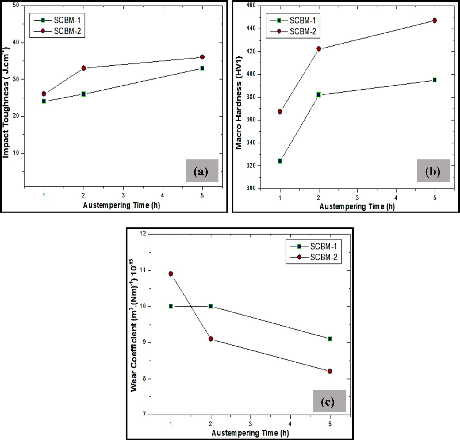
Figure 8 shows the worn surfaces of the samples. There are evidence of adhesive wear tracks on the wear surface of the S specimen (Figure 8(a)). This is an expected situation in materials with low hardness. Small chips may also be seen sticking on the SEM surface. Although the SEM worn surfaces of the TM sample are smoother, small thin plate fractured particles were seen in some areas. As in the TM sample, fractures can be seen in the carbon-rich martensitic phases, especially during vibratory wear (Figure 8(b)). However, despite this situation, less wear coefficient occurs. As seen in the Figure 8(c), the tracks on the surface of FBM specimens are less deep. Adhesive wear and abrasive wear indications are not seen. Deep and wide goove tracks are also observed on the worn surface of the SCBM 1-5 specimens. These traces are thought to be caused by the fragments broken off from the specimen (Figure 8(d)). However, in the SCBM 2-5 sample with the lowest wear coefficient, smoother and non-deep tracks were observed on the worn surface (Figure 8(e)).
SEM worn surfaces of the specimens (a) S, (b) TM, (c) FBM, (d) SCBM 1-5, (e) SCBM 2-5.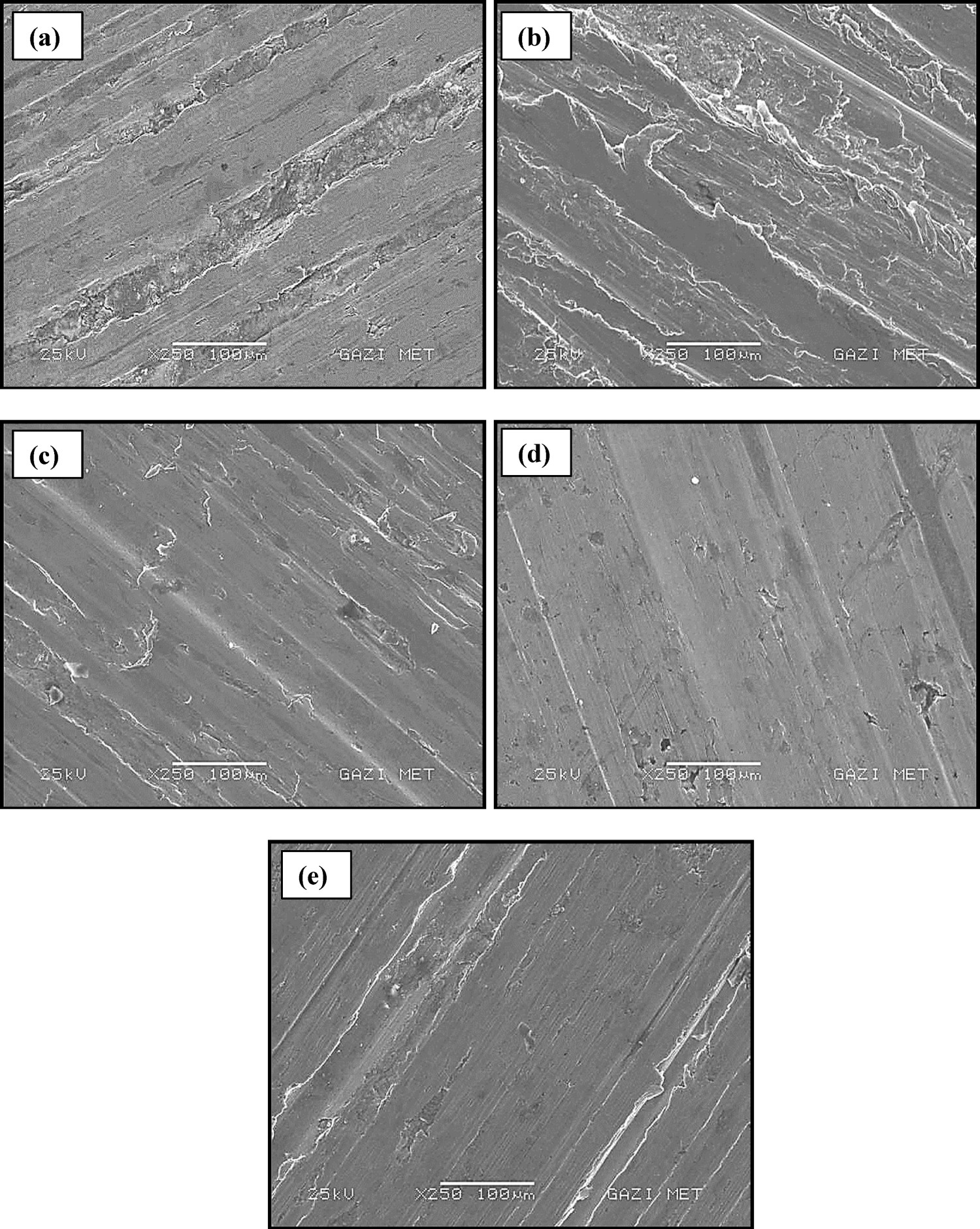
Among the heat treated specimens, the hardness values of TM, FBM, SCBM 2-5 specimens are close to each other and at the highest level. Although TM specimen has similar wear resistance with similar hardness FBM specimen, their impact toughness values are significantly low since it contains martensitic phase. The highest impact toughness value was determined as 36 J.cm−2 in the SCBM 2-5 specimen and it was developed approximately 500% compared to the TM specimen. It is seen that the wear coefficient values are also significantly reduced in all SCBM specimens. This improvement provided the minimum wear coefficient for the SCBM 1-5 and SCBM 2-5 specimens with the increase of the austempering time. It was found that the wear resistance of the SCBM specimens was significantly improved compared to conventional bainitic and martensitic microstructures. It was observed that the wear resistance of these samples was further improved by increasing the austempering time.
Footnotes
Disclosure statement
No potential conflict of interest was reported by the author(s).