
Abstract
The quenched M50NiL steel was plasma nitrided at 460°C for different time to investigate the effects of the duration time on the microstructure, microhardness and wear resistance of the nitrided layers. The results show that the plasma nitrided layer depth increases with increasing nitriding time. The plasma nitrided layer includes only the diffusion layer without compound layer. The main phases in the nitrided surface layer are nitrogen expended α′-Fe and γ′-Fe4N. The microstructure of the nitrided layer is refined. The wear resistance of the nitrided samples can be improved significantly by plasma nitriding. The sample nitrided for 4 h possesses the highest wear resistance, due to its relatively smooth surface and ultra-fine grains in the nitrided layer.
Introduction
M50NiL steel is categorised as a low carbon high alloy steel with both high strength and high fracture toughness. 1 It has been widely used in aerospace and industrial applications as bearings and gear transmissions. 2 In practice, the bearings and gears should exhibit superior mechanical properties, such as high fracture toughness, good wear and corrosion resistances at high operation temperature and high speed. 3 Thus, the surface treatment of the M50NiL steel is indispensable to further improve its surface mechanical properties. To our knowledge, the majority of studies for surface treatment of M50NiL steel have been conducted by using gas carburising and nitrocarburising.4–6
Plasma nitriding treatment is usually used to improve the surface properties of various steels.7,8 The low temperature plasma nitriding is usually carried out at temperatures varying from 400 to 500°C.9,10 When nitriding temperature is higher, the structure of the nitrided layer will be coarsened, leading to a reduction of mechanical properties. 11 When nitriding temperature is lower, the structure of the nitrided layer will be compact and uniform, but the thickness of the nitrided layer is thinner. 12 Therefore, nitriding at low temperature for a long time can both to create a thick layer on the surface and to retain mechanical properties.
More recently, our primary study has been done on this steel modified by plasma nitriding at different temperatures. 13 The present investigation is to further study plasma nitriding of quenched M50NiL steel at low temperature (460°C) for different time. Then, the effects of duration time on the microstructure, hardness and wear property of the surface layer were systematically investigated.
Experimental
Materials
The as received M50NiL steel was tested by X-ray fluorescence spectroscopy (AXIOS-PW4400), and the chemical composition is (wt-%) 0.13 C, 4.06 Cr, 3.26 Ni, 3.78 Mo, 1.25 V, 0.30 Mn, 0.12 Si, 0.012 P, 0.002 S, and Fe balance. Prior to plasma nitriding, all samples were solution-heat treated at 980°C for 1.2 h, then quenched in oil. The bulk microhardness of the quenched M50NiL steel is 430 HV0.1. The samples were machined to 10 × 10 × 4 mm and then the top and side faces were grounded using silicon carbide papers from 240 to 800 grades.
Plasma treatment
Plasma nitriding treatments were carried out in a 30 kW plasma nitriding unit (LDMC-30t). The plasma was generated by a pulsed direct current power supply operating at 650 V. Before the application of glow discharge, the furnace chamber was evacuated to below 10 Pa by a rotary pump. In the beginning of nitriding treatment, 0.1 L min−1 hydrogen was put into the furnace chamber for 0.5 h at 150°C to remove surface oxides of the samples and obtain an uniform surface through the ion sputtering cleanout. The samples were plasma nitrided at 460°C for 2, 4, 8 and 16 h in mixed gas of 0.05 L min−1 N2 and 0.4 L min−1 H2 at a constant pressure of 280 Pa.
Characterisation
The cross-sectional microstructure, surfaces morphologies and the elemental distributions were detected on a scanning electron microscope (FEI QUANTA 200F) coupled with energy dispersive X-ray spectrometer (EDS) facility. The phase structure in the nitrided surface was analysed by using the X-ray diffraction (XRD, type D/max-rB) with Cu-Kα radiation (λ = 0.15406 nm) in the range of angles 30–90° at 40 kV and 30 mA with 0.05° interval step mode. The glancing incidence XRD (GIXRD) was performed on a Philips X'Pert diffractometer with Cu-Ka radiation, in the range of angles 30–90° with the incidence angle of 1°, step size of 0.02° and time per step of 2 s. Microstructural feature of nitrided surface were characterised by transmission electron microscope (TEM, Tecnai G2 F30) with an accelerating voltage of 300 kV. The indentation tests were performed to evaluate the surface hardness by using a Nano Indenter XP (MTS). Microhardness profiles of the nitrided layers were measured at 3 μm underneath surface by Vickers microhardness tester (HV-1000) under an indentation load of 100 g for 15 s. To ensure the measurement precision, the average value of three indentations placed at the same depth into the nitrided layer was used.
Wear properties of the quenched and nitrided M50NiL steel samples were evaluated using a pin-on-disk apparatus (POD-I).
13
During the test, the samples were rotated against a stationary WC ball (2000 HV0.1) of 5 mm diameter at the rotation speed of 200 r min−1 (0.1 m s−1) for 3600 s under a constant load of 10 N. The circle diameter of the wear track was about 8 mm. The friction coefficient was continuously recorded during the test by a computer. All tests were conducted in air (temperature 20°C, humidity 50% RH) without lubrication. After the wear test, the worn volume was calculated by integrating the area across the wear scar profile measured by PGI 1240 stylus profilometer, and then multiplying the length of the tracks. To ensure a high accuracy of the worn volume, the average value of three measurements was used. Volume wear rate, η, was calculated according to the following equation:

Results and discussion
Surface characteristics and microstructures
Surface morphologies of plasma nitrided M50NiL steel samples and EDS result in region A are shown in Fig. 1. It is shown that all nitrided surfaces are covered by uniformly distributed nano-sized nitride particles. The particles size for the 2, 4, 8 and 16 h nitrided samples are about 0.09–0.12 μm, 0.18–0.34 μm, 0.55–0.64 μm and 0.79–1.40 μm, respectively. The size of the nitride particles increases with the increase of nitriding time. Moreover, it can be seen that some larger and irregular nitride particles distribute dispersively on the nitrided surface when the nitriding time increases to 16 h (Fig. 1d). This may be caused by continuous sputtering and redeposition of the surface sputtered atoms on the surface.
14
Surface morphologies of the plasma nitrided M50NiL steel samples a 2, b 4, c 8 and d 16 h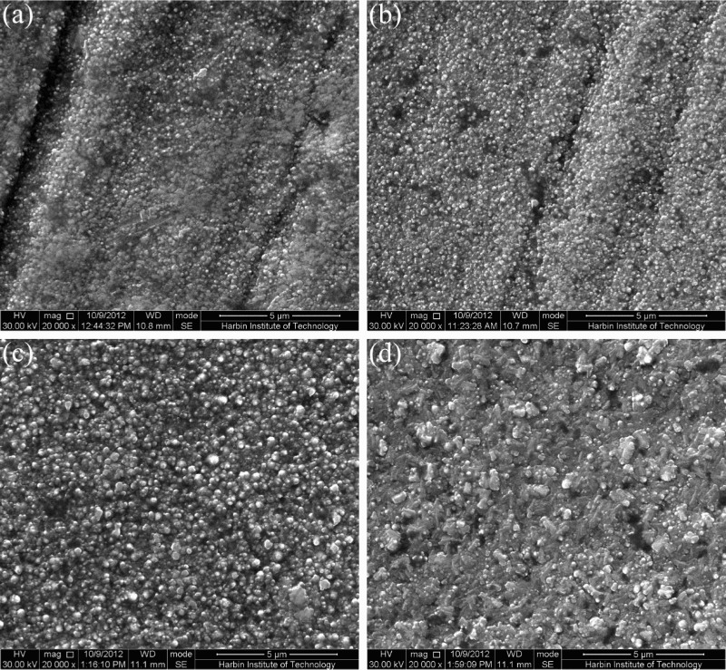
Figure 2 shows the cross-sectional microstructures of the surface layers of plasma nitrided M50NiL steel samples. It is shown that the plasma nitrided layers are characterised only by the diffusion layer without compound layer. The layer depths of the 2, 4, 8 and 16 h nitrided samples are 39.47, 58.46, 82.85 and 107.37 μm, respectively. The thickness of the nitrided layer increases with increasing nitriding time and conforms approximately to the parabolic law. Moreover, with the increase of nitriding time, the microstructure of the nitrided layer is slightly coarsened (Fig. 2c and d).
Cross-sectional morphologies of the plasma nitrided layers produced on M50NiL steel samples by plasma nitriding at 460°C for a 2, b 4, c 8 and d 16 h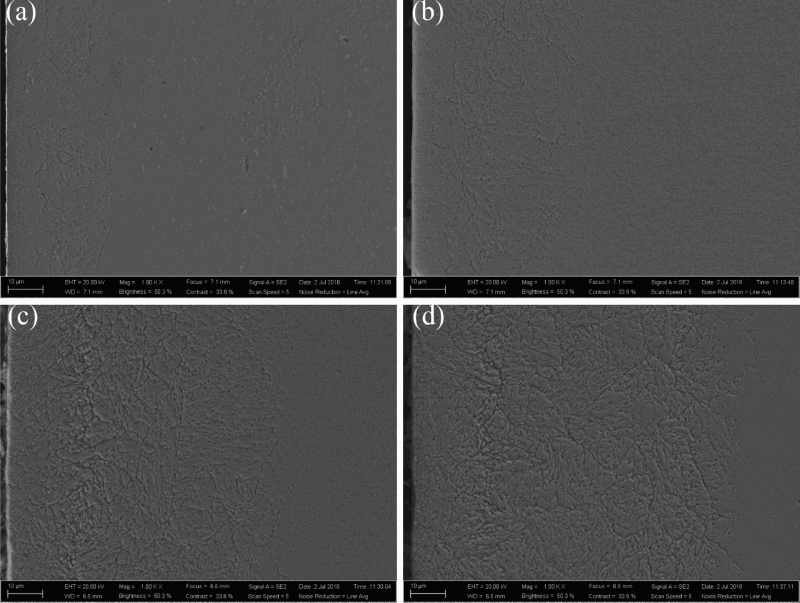
Phase structure of the nitrided layer
Figure 3 shows the XRD patterns of surface layers of the quenched and nitrided samples. The quenched sample shows sharp Bragg reflection peaks, corresponding to martensite and a few undissolved alloy carbide M6C (may be complex carbides that are formed from carbide forming elements like Cr, Mo and V) phase.
a XRD patterns of the quenched and plasma nitrided M50NiL steel samples and b XRD pattern of the 16 h nitrided sample obtained by GIXRD technique at 1° incidence angle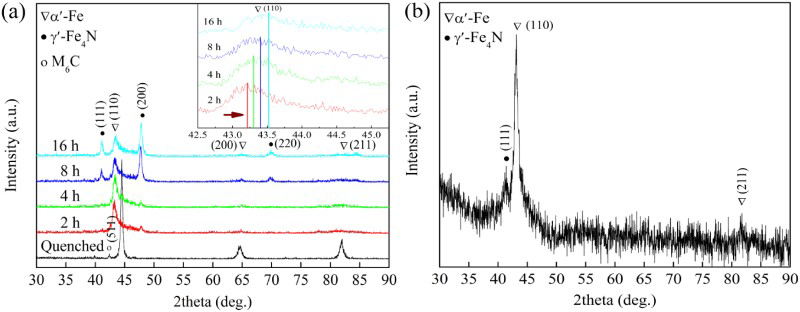
The phases of the nitrided samples consist dominantly of nitrogen expended martensite α′-Fe 15 and γ′-Fe4N phases. This also demonstrates that there is only diffusion layer (without ε-Fe2-3N phase). The larger and irregular nitride particles on the surface of the 16 h nitrided sample (see Fig. 1d) are verified by GIXRD, which is the γ′-Fe4N phase, as shown in Fig. 3b. Moreover, it can be seen that the α′-Fe (110) peaks of the nitrided samples shift to a lower angle as compared to the α′-Fe (110) peak of the quenched sample. This can be attributed to the incorporation of nitrogen into the α′-Fe lattice. 16 From the inset of Fig. 3, the shifting extent of the α′-Fe (110) peak decreases with increasing nitriding time (as marked by the arrow in the inset), which indicates a decrease of the solid solution amount of nitrogen element in α′-Fe. 5 From Fig. 3a, it can be seen that the proportion of γ′-Fe4N phase slightly increases with increasing nitriding time, indicating that some nitrogen atoms in the α′-Fe lattice transfer to γ′-Fe4N lattice, therefore decreasing the degree of supersaturated nitrogen in the surface layer. It is also observed that the α′-Fe (110) peaks of the nitrided samples are broadened, which could be probably caused by the decrease in grain size. 17
The TEM micrograph and corresponding selected-area electron diffraction (SAED) of the surface nitrided at 460°C for different time are shown in Fig. 4. It can be seen that there are many dislocations and stacking faults in the bright field images of the 2 and 4 h nitrided samples, as shown in Fig. 4a, b. The corresponding SAED patterns (insets in Fig. 4a, b) present the characteristic of concentric rings, indicating the formation of ultra-fine phase which can be marked as single-phase α′-Fe. The TEM images of the 8 and 16 h nitrided samples are shown in Fig. 4c, d. It can be seen that there are also some dislocations and stacking faults in the bright field image, but the dislocation density is decreased. The corresponding SAED patterns (insets in Fig. 4c, d) present the characteristic of concentric intermittent rings, also indicating the formation of ultra-fine phase, which are marked as α′-Fe and γ′-Fe4N phases. However, the degree of grain refinement is decreased. In comparison, the diffraction rings of the 4 h nitrided sample are continuous and strong, indicating smaller grains in surface layer, which would be beneficial to wear resistance improvement.
18
TEM micrographs of the surface of the plasma nitrided samples a 2, b 4, c 8 and d 16 h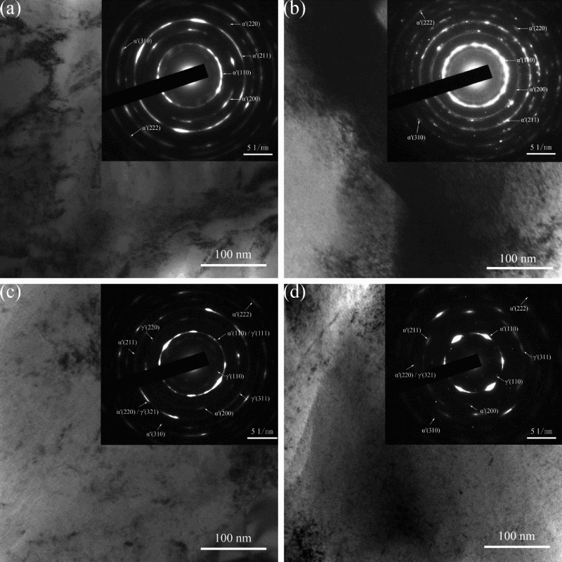
Hardness profile
Figure 5 shows the microhardness profiles in surface layer of M50NiL steel plasma nitrided at 460°C for different time. The surface hardness measured by the indentation tests is 14.17, 14.06, 12.46 and 9.4 GPa for the 2, 4, 8 and 16 h nitrided samples, respectively. The surface hardness of the nitrided samples decreases slightly with increasing nitriding time, which could be mainly caused by the deterioration of microstructure and increased grain size of nitrides. The thickness of the effective hardened layer (as shown at the sits of dash lines) increases monotonously with increasing nitriding time, which is in well agreement with above microstructure observations. The matrix microhardness of the 2, 4, 8 and 16 h nitrided samples is 421 HV0.1, 410 HV0.1, 415 HV0.1 and 406 HV0.1, respectively, which is slightly lower than the quenched one (430 HV0.1). This indicates that tempering effect simultaneously with plasma nitriding treatment.
Microhardness profiles in surface layer of M50NiL steel samples plasma nitrided at 460°C for different time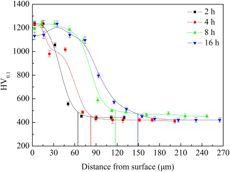
Wear properties
Friction coefficients and wear rates
Figure 6 shows the friction coefficients of the quenched and nitrided M50NiL steel samples sliding against WC ball for 3600 s under 10 N loading. For the quenched sample, in the early stage (t < 800 s), the friction coefficient of the quenched sample immediately increases to a high value between 0.5 and 0.6 with a severe oscillation, then gradually decreases to a stable value. Compared with that of the quenched sample, the friction coefficients of the nitrided samples are lower in the initial stage, then increase to a stable state. In the stable stage, the friction coefficients of 2, 4, 8 and 16 h nitrided samples are about 0.44, 0.37, 0.43 and 0.48, respectively. The friction coefficient of the nitrided samples decreases first then increases with increasing treatment time. The 4 h nitrided sample has the lowest friction coefficient.
Frictional coefficient curves of the quenched and plasma nitrided M50NiL steel samples sliding with a WC ball under 10 N for 3600 s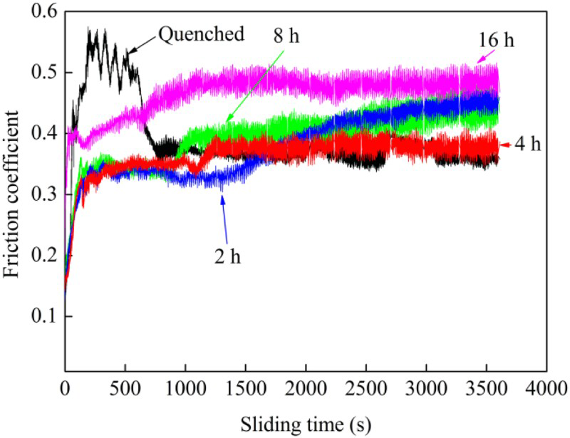
The volume wear rates of the quenched and nitrided M50NiL steel samples are calculated by equation (1), as shown in Fig. 7. The volume wear rates are about 252.3 × 10⁻⁵, 4.3 × 10⁻⁵, 3.1 × 10⁻⁵, 3.9 × 10⁻⁵ and 4.7 × 10⁻⁵ mm3 m−1 for the quenched, 2, 4, 8 and 16 h nitrided samples, respectively. It can be seen that the volume wear rates of the nitrided samples can be significantly decreased. This indicates that plasma nitriding can dramatically enhance the wear resistance of M50NiL steel. Especially, the volume wear rate of the 4 h nitrided sample is the lowest, about only 1.2% of that for the quenched one, indicating a higher wear resistance.
Volume wear rates of the quenched and plasma nitrided M50NiL steel samples sliding with a WC ball under 10 N for 3600 s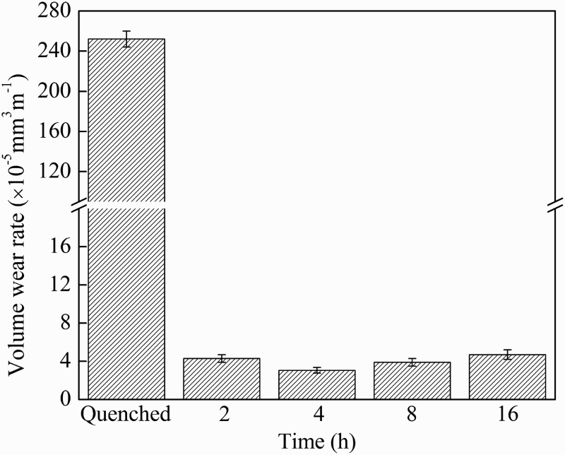
Wear mechanisms
The wear tracks of the quenched and nitrided M50NiL steel samples after sliding with a WC ball under 10 N for 3600 s are shown in Fig. 8. The EDS analysis results in regions A–E are shown in Table 1. For the quenched sample (Fig. 8a), the width of the wear track is wide (about 1.12 mm) and deep, showing severe roughening, tearing and plastic deformation with fatigue cracks, spalling notches and many wear debris in partial plowing grooves. Because the hardness difference between the quenched sample (430 HV0.1) and the counter WC ball (2000 HV0.1) is big, the contact area is easily adhered in the early stage, therefore leading to a high friction coefficient in the early stage.
6
Worn surfaces of the quenched and plasma nitrided M50NiL steel samples after sliding with a WC ball under load 10 N for 3600 s a quenched, b 2 h, c 4 h, d 8 h and e 16 h EDS results for the regions A–E in Fig. 8a–e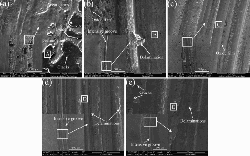
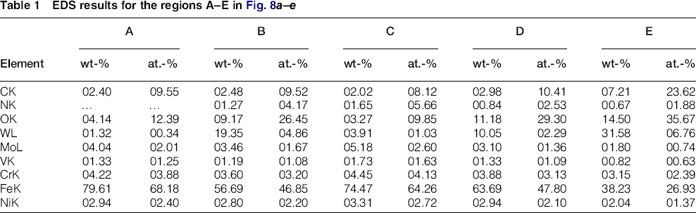
The EDS result in region A shows that there is a small amount of wolfram, indicating material transference from WC ball to the counter surface due to severe adhesion. Meanwhile, the oxygen is detected in region A (Table 1), indicating that there is a high flash temperature between the wear counterparts, consistent with the feature of oxidative wear. 19 In the later stage, the friction heat is high during the dry sliding, and a thick and compacted oxide film is formed on the surface. The oxide film can perform a self-lubricating role and protect the surface against the counter WC ball, leading to the reduction of the friction coefficient. 20 Thus, the main wear mechanism of the quenched sample is severe adhesive wear and oxidative wear.
Compared with that of the quenched sample, the worn surfaces of the nitrided samples are obviously shallow and superficial, indicating plasma nitriding treatment can improve the wear resistance, as shown in Fig. 8b–e. The worn surfaces show mild adhesive wear with some parallel abrasion grooves. According to Table 1, EDS results for regions B–E (Fig. 8b–e) show that there are also material transference from WC ball and oxidation wear in the worn surface as mentioned above. But the concentration of wolfram is higher, indicating higher wear loss of the WC ball.
It is also observed that there are intensive abrasive grooves on the worn surface of the 2, 8 and 16 h nitrided samples (Fig. 8b, d and e), indicating that more severe abrasive wear occurred on the surface, therefore leading to a higher wear rate. The relatively high wear rate of the 2 h nitrided sample can be ascribed to relatively less γ′-Fe4N formation on the surface and larger surface roughness. For the 8 and 16 h nitrided samples, the higher wear rate might be due to the coarsening microstructure and nitrides, more defects (such as micropore and microcrack) in the nitrided layer and a third-body abrasion effect of nitride particles. 21 Therefore, due to the synergistic effects of relatively smooth surface, hardness and ultra-fine phase in the nitrided layer, the 4 h nitrided sample possesses the best wear resistance.
Conclusions
Plasma nitriding is demonstrated to be an effective process to produce hard, thick and wear resistant layers on the surface of the quenched M50NiL steel.
The plasma nitrided layer includes only the diffusion layer, without compound layer. The thickness of the nitrided layer increases with increasing nitriding time. The phases in the surface of M50NiL steel samples nitrided at 460°C for different time are mainly of nitrogen expended α′-Fe and γ′-Fe4N. The microstructures of the nitrided layers are ultra-refined. Wear resistance of the M50NiL steel samples nitrided at 460°C for different time can be dramatically improved. The wear mechanisms of the nitrided samples are mild abrasive and oxidation wear. The 4 h nitrided sample has the best wear resistance, due to its synergistic effects of relatively smooth surface, hardness, ultra-fine phase and high stress in the nitrided layer.
Footnotes
Acknowledgements
The authors gratefully acknowledge the National Natural Science Foundation of China (Grant No. 51371070 and 51401062) for the financial support of this research work.