
Abstract
Ti, Co, Cr, Fe, Ni and graphite powders were used to fabricate TiC reinforced CoCrFeNi composite by mechanical alloying and consequently hot pressing sintering at 1200°C for 1 h. Results indicated that Co, Cr, Fe and Ni powders were deformed, cold welded and crushed repeatedly during milling and an face-centred cubic-structured solid solution was obtained after milled for more than 10 h. Nano-sized TiC and micron-sized Cr7C3 type carbides were formed and embedded in the CoCrFeNi matrix dispersedly after sintering. The hardness and compressive fracture strength of the sintered composite reached 501 HV and 2.55 GPa, respectively, which could be ascribed to the presence of large amount of in-situ formed TiC and Cr7C3 type carbides in the composite.
Introduction
High-entropy alloys (HEAs), as a new design concept, were first proposed by Yeh and co-workers in 1995 [1,2] and were initially defined to consist of at least five principal elements of concentrations between 5 and 35 at.-%. Four core effects in HEAs [3,4], namely high mixing entropy effect, sluggish diffusion effect, cocktail effect and lattice distortion effect, caused many interesting microstructure and properties. It was reported that HEAs possess excellent resistance to heat [5,6], oxidation [7], corrosion [8] and well soft magnetic [9,10], thus, attracted more and more attention in recent years. However, some of the HEAs exhibit very limited tensile ductility due to undetected intermetallic phase formation or due to any unknown intrinsic limitations of such multi-component systems with strong solid solution hardening. The presence of such unpredicted intermetallic phase in the microstructure of multi-component systems is harmful to the ductility of the materials and cause uncontrollable of their microstructure and properties.
In recent years, literatures reported a range of HEAs with a single face-centred cubic (FCC) structure (single-phase HEAs) which exhibited good ductility and bright prospect in engineering applications [11-13]. Otto et al. [12] reported that the equiatomic CoCrFeNi single-phase HEA exhibited very low yield strength (136 MPa), hardness (135 HV) but high ductility (75%) in homogenised state. Pradeep et al. [13] reported a new non-equiatomic CoCrFeMnNi single solid solution phase HEA which also has very low yield strength (93 MPa) but excellent elongation (58%) at homogenised state. These results suggest that the solid solution hardening effect in these equiatomic and non-equiatomic single-phase HEAs is extremely limited caused by the small atomic size difference between the composed elements (mostly the Fe-group element). Therefore, the strength and hardness of single-phase HEAs at as-cast and as-homogenised state are rather low. Although cold processing increased the yield strength of the HEAs, it dramatically decreased after recrystallisation [13]. The low strength of the alloys at cast, homogenised and recrystallised states greatly limits the broad application of these single solid solution phase HEAs.
Dispersion strengthening is a widely used approach to enhance materials, such as oxide dispersion strengthened alloys [14,15], carbide dispersion strengthened alloys [16], etc. These reinforcement phase significantly improve the properties of the matrix materials, even in HEAs. Rogal et al. [14] investigated the microstructure and mechanical properties of Al2O3 nano-particles reinforced equiatomic CoCrFeMnNi alloy, which suggested that nano-sized Al2O3 homogeneously embedded into the HEA matrix and thus significantly improved yield strength. However, the poor wettability of HEA matrix on Al2O3 likely resulted in the presence of porosity in composites. Carbide is apparently as a promising reinforcement phase for single-phase solid solution HEAs due to its high hardness, excellent wear resistance, superior oxidation resistance and high thermal stability. SiC nano-particles were introduced to fabricate ex-situ 5%SiC-CoCrFeMnNi composites [16], which exhibited excellent mechanical properties with yield strength of 1480 MPa and plasticity of 31%. There have also been reported that HEAs as a binder in WC with Al0.5CoCrCuFeNi [17] and in Ti(C,N)-based cermets of AlCoCrFeNi [18], which caused almost full dense sintered green bodies and significant improvements in mechanical properties [19]. However, few were reported about the in-situ synthesis of carbide reinforced single-phase HEAs and their characterisation.
In this study, in-situ TiC reinforced CoCrFeNi composite was prepared via high energy ball milling and hot pressing sintering process. The phase structure and morphology of milled powders were characterised, as well as the microstructure and mechanical properties of sintered composites were also investigated.
Experimental details
Physical property of the constituents in CoCrFeNiTi0.2C0.2.

To avoid the formation of various unpredicted intermetallic phases or carbides, such as TiNi intermetallic, chromium carbide and ferric carbide, during milling process, a ‘two-step’ milling schedule was used in this paper. First, heavy transition metal powders Co, Cr, Fe and Ni were initially mechanically milled with equiatomic molar ratio. Fifteen grams metal mixed powders were placed with 300 g stainless steel balls together, which was corresponded to a ball to powder ratio 20:1, in a 900 ml stainless steel jar. High-energy ball milling was performed at a speed of 350 rev min−1 for 2, 6, 10, 22 and 46 h under argon atmosphere using a planetary mill (QM-WX4). Second, Ti and C powders with 2 wt-% ethanol were added and then milled for 2 h at a speed of 150 rev min−1 to increase the homogeneity and yield of powders. The milled powders were dried at 85°C and sieved by 200 mesh to obtain the CoCrFeNiTi0.2C0.2 composite powders. The sieved powders were then held in 12.5 mm diameter graphite die and were sintered for 1 h with a pressure of 50 MPa at 1200°C in ZT-25-20YVHP equipment. In addition, CoCrFeNi alloy was also prepared via the similar process for comparison.
The microstructure and chemical compositions of the CoCrFeNiTi0.2C0.2 composite and CoCrFeNi alloy were examined using scanning electron microscopy (SEM, HITACHI-S3000), transmission electron microscopy (TEM, JEOL-2100) and energy dispersive spectrometer (EDS). A thin foil TEM sample was prepared by a precision ion polishing system (Gatan 691) at room temperature. The crystal structure was identified by X-ray diffraction (XRD) with a Cu Kα radiation (Bruker D8, λ = 0.15406 nm), at 15 kV voltage, 30 mA current, 15° to 80° scanning angle (2θ) and 12°/min scanning speed. The density of the material was measured with Archimedes draining method. The hardness was measured using a digital Vickers hardness tester (HVS-50) under a load of 98 N for 15 s. The average value was obtained by taking five points for each specimen. The magnetic property of the composites was characterised by a vibrating sample magnetometer (Lake Shore 7404) at room temperature by using a maximum applied field of 10,000 Oe. Ten micro metre thick and 5 mm diameter VHP samples were prepared for compressive tests by using a material testing machine (CHUN-YENCY6040A4) with a strain rate of 2 × 10⁻³ s−1.
Results and discussion
Microstructure and phase evolution of CoCrFeNiTi0.2C0.2 composite powders during milling
To obtain a pre-alloyed CoCrFeNi solid solution, the heavy transition elements powders were high energy ball milled at the first milling stage, and the alloying behaviour was discussed in this section. XRD pattern shown in Figure 1 reveals the phase formation in CoCrFeNiTi0.2C0.2 composite powders milled at a speed of 350 rev min−1 for various milling time. Diffraction patterns of all the pure elements were presented in the raw powders. After the powders were milled for 2 h, Co diffraction peaks firstly disappeared indicating the formation of a solid solution phase with a FCC structure (similar with the Ni lattice), while the intensity of existing peaks decreased dramatically. In addition, the peaks for Cr and/or Fe with a bcc structure were still visible indicating that Cr and/or Fe elements were not completely dissolved into the FCC lattice. The peak intensity of Cr and/or Fe was further decreased and the obvious peak broadening was observed as the powders were milled for 6 h. Peak broadening can be ascribed to the crystallite size refinement, high lattice strain and crystallinity decrease. The Cr and/or Fe peaks were absent after the powders were milled for 10 h. As the milling time was further prolonged, the only existing peaks are identified as a single-phase solid solution with the FCC lattice structure. Careful examination of the results suggested that the Bragg angle of (111) peak of FCC phase was shifting toward low angle with increasing milling time. It could be inferred that the lattice parameter of FCC phase increased during milling which was mainly attributed to the gradually diffusing of big solute atoms (i.e. Fe, Cr and Ti) into its lattice. Previous research has shown that the element with lower melting point or elements with similar crystal structures and atomic sizes tend to dissolve into each other and form solid solutions [20]. According to the physical properties of the constituents in the CoCrFeNi HEA (as listed in Table 1) and the XRD results, the anticipated alloying sequence for CoCrFeNi alloy is probably as follows: Ni→Co →Fe→Cr.
XRD patterns of CoCrFeNiTi0.2C0.2 powders milled at a speed of 350 rev min−1 for various milling duration.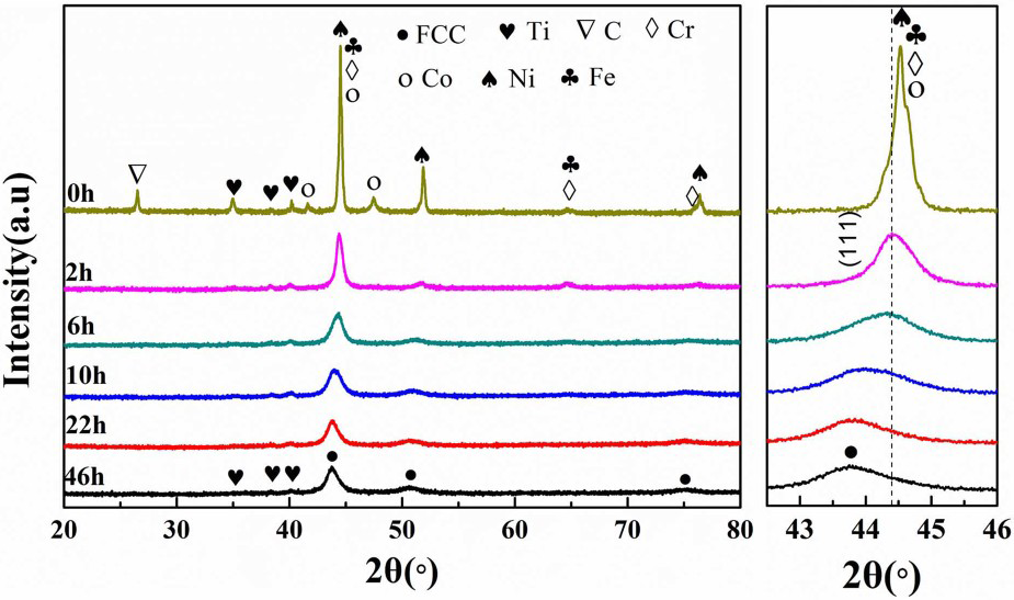
Moreover, graphite peaks were absent as the Ti and C powders were milled for 2 h with a relative low milling speed, indicating the formation of amorphous phase. The intensity of Ti peaks gradually decreased with an increase in milling time for Co, Cr, Fe and Ni powders during the first milling stage. The result indicated that partial of Ti atoms were diffused into the lattice of the FCC phase during the second milling stage, and the solution degree in the FCC phase increased with increasing milling time. This phenomenon was likely related to the formation of large a number of defects (i.e. voids and dislocations) during milling the heavy transition elements which provided passages for Ti atoms to diffuse quickly.
SEM images of powders with different milling duration were presented in Figure 2. Figure 2(a) shows the morphology of the mixed raw powders. As the milling time increased from 2 to 6 h, severe agglomerations with irregular block appearance were observed (Figure 2(b, c)), and the particles were in a wide size range approximately from 2 to 35 µm. After milling for 10 h, the particles became more homogenously and the average size of particles significantly decreased to less than 10 µm, referring to Figure 2(d). It was worth noting that most of the milled powders became coarsing and exhibited a laminar appearance (Figure 2(e)) when the milling time increased to 22 h, resulting from the significantly impact deformation of powders during milling. As the milling time further increased to 46 h, partial of the laminar agglomerates were changed into equiaxed particles with a fine particle size. The microstructure evolution of milled powders indicated that the powders passed through a deformation – cold-welding – broken – cold-welding – broken procedure during milling, which was the typical characteristics of the ductility powders during milling process [20,21]. The inset in Figure 2(d) shows the SEM-EDS result of the CoCrFeNiTi0.2C0.2 composite powders milled for 10 h with a ball to powder ratio 20:1. Since carbon cannot be accurately quantified from EDS results only the metallic constituents of the alloys are quantified and listed. The contents of metallic components in the milled composite powders were close to the targeted equimolar ratio. Referring to Figures 1 and 2(d), the Co, Cr, Fe and Ni element powders were fully alloyed and formed a single-phase solid solution with FCC structure as the milling time reached 10 h and the milled powders exhibiting a relatively small particle size. Therefore the 10 h milled powders were hot pressing sintered at 1200°C for 1 h for fabricating the green bodies.
SEM images of the CoCrFeNiTi0.2C0.2 powders milled at a speed of 350 rev min−1 for various milling duration: (a) 0 h, (b) 2 h, (c) 6 h, (d) 10 h, (e) 22 h and (f) 46 h.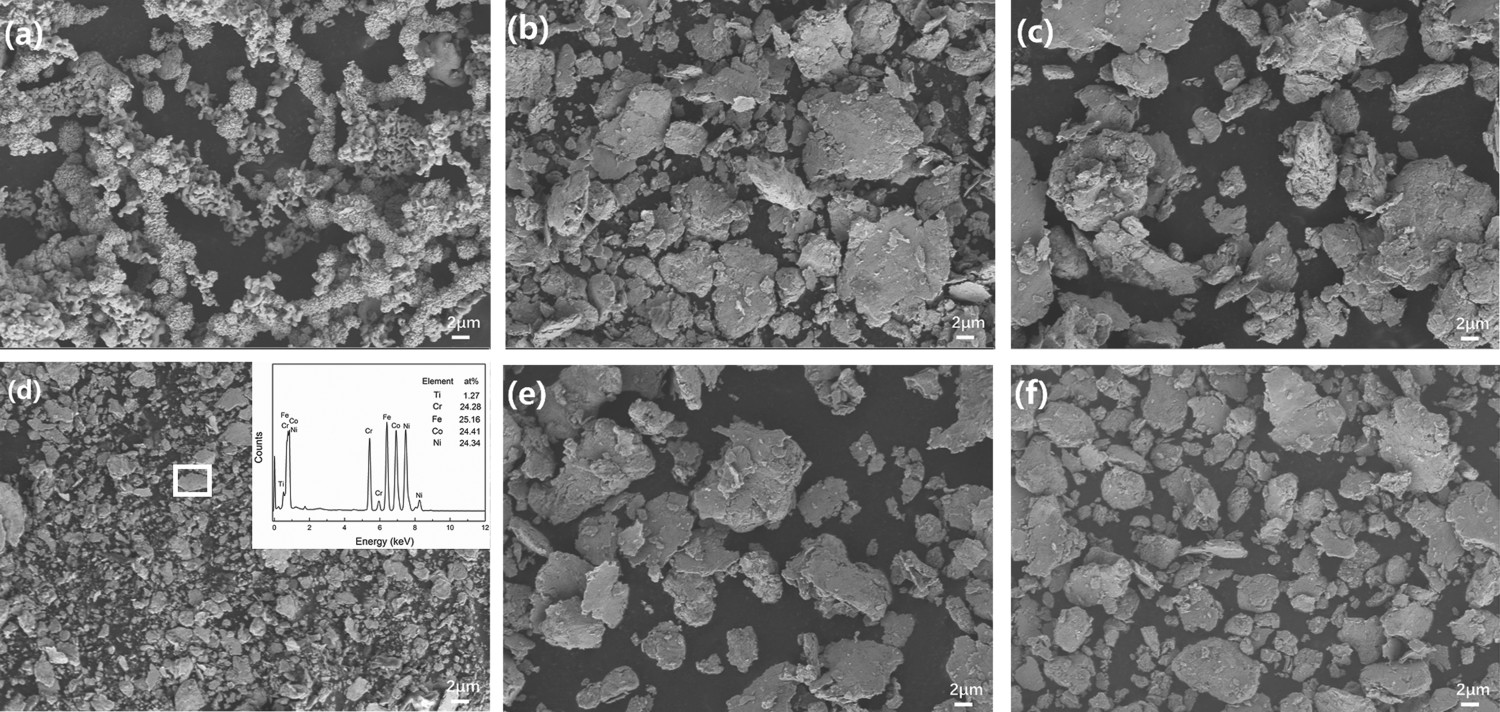
Characteristics of the sintered composite
Figure 3 presents the XRD pattern of CoCrFeNi and CoCrFeNiTi0.2C0.2 sintered at 1200°C for 1 h. Only a single FCC phase was observed for the sintered equimolar ratio CoCrFeNi HEA, referring to Figure 3. While the Bragg peaks are identified as three main phases corresponding to FCC, TiC and Cr7C3 for the sintered CoCrFeNiTi0.2C0.2 composites. The results indicated that Ti and Cr atoms would be likely reacted with C atoms resulting in the formation of TiC and Cr7C3 type carbides after hot pressing sintered at 1200°C for 1h in CoCrFeNiTi0.2C0.2 composites. Moreover, the content of Cr7C3 might be even higher than TiC carbide in sintered green bodies since the relative peak intensity ratio of Cr7C3 to the FCC phase was bigger than that of TiC to FCC phase. The formation of the carbides was mainly caused by the high affinity between Cr-C and Ti-C atoms. During the sintering process, the following reactions (1)–(3) are expected to occur in CoCrFeNiTi0.2C0.2:
XRD patterns of CoCrFeNi and CoCrFeNiTi0.2C0.2 composite sintered at 1200°C for 1 h


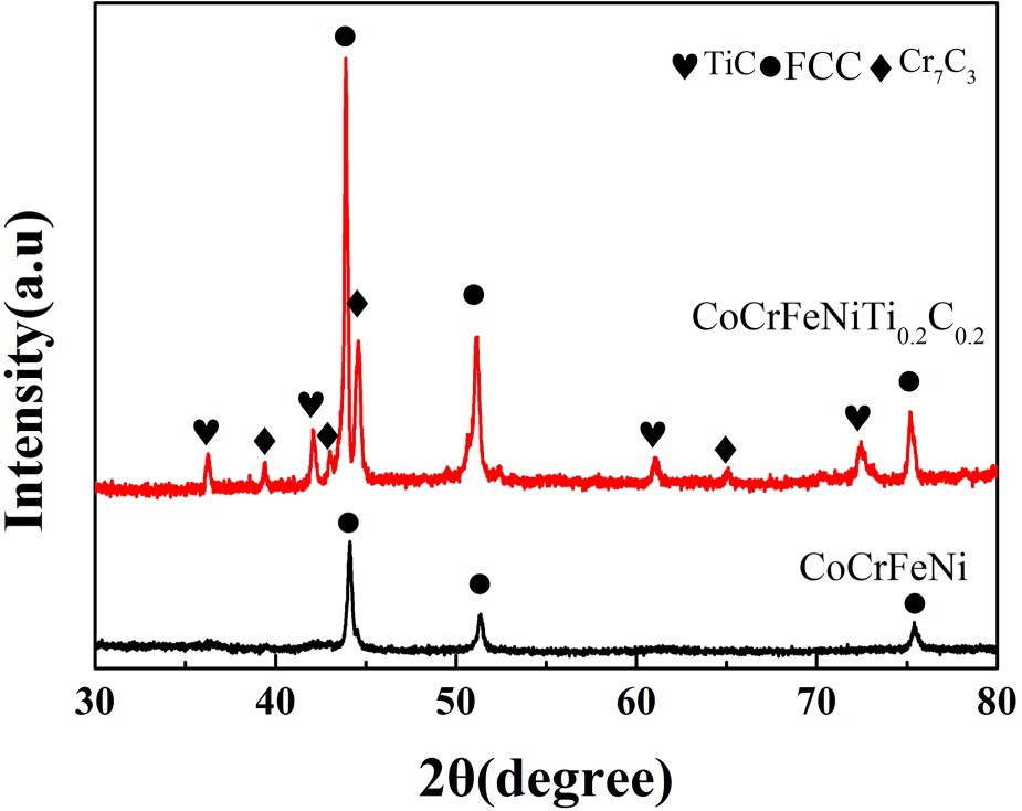
At the sintering temperature (1200°C), the Gibbs free energy ΔGf and reaction equilibrium constant K of formation of TiC, Cr7C3 and Fe3C carbides are −165.8 kJ mol−1, 5.94 × 10⁵, −207.5 kJ mol−1, 1.69 × 10⁷ and 1.485 kJ mol−1, 1.0001 [22], respectively. This implies only reaction (1) and (2) are spontaneous reactions at 1200°C, reaction (3) is unlikely occurred since Fe3C is unstable at 1200°C. Moreover, reaction (2) has a higher conversion ratio than reaction (1). The great driving force for reaction (2) would likely result in the formation of large amount of Cr7C3 during sintering which is in consistent with the XRD result shown in Figure 3. Therefore, although the electronegativity difference in Ti and C is bigger than Cr and C (shown in Table 1), considerable amount of Cr7C3 formed during sintering. Similarly, Wang et al. [23] examined a C-doped CoCrFeNiMn HEA in which M7C3 and/or M23C6 carbides were present depending on the annealing conditions.
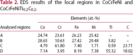
Figure 4 show the SEM/BSE micrograph and EDS results of the CoCrFeNi alloy and CoCrFeNiTi0.2C0.2 composite sintered at 1200°C for 1 h. A homogenous microstructure without other contrast was observed in sintered CoCrFeNi alloy, referring to Figure 4(a). Combined with the XRD results shown in Figure 3, it could be inferred that Co, Cr, Fe and Ni elements were evenly distributed in the alloy and kept a solid solution phase with FCC structure after hot press sintering. Referring to Figure 4(b), quantities of black spherical phases (region C) and dark grey equiaxed blocks (region D) were embedded in a grey matrix (region B) homogeneously in sintered CoCrFeNiTi0.2C0.2 composite. The sizes of dark grey equiaxed blocks and black spherical phases were in the range of 1–3 µm and 80–950 nm, respectively. Since the brightness of micrographs exhibited in the SEM-BSE mode is strongly dependent upon the average atomic number of the chemical constituent [24], regions C and D are likely contained light elements (i.e. C, Ti and Cr). Figure 4(c–f) presents the energy dispersive spectral of the regions A–D in Figure 4, respectively, and the results were listed in Table 2. Noting that only the metallic components are credible since carbon cannot be accurately quantified from EDS. And the results of black spherical phase are not accurate, since in the sintered bodies the phase was present only in small regions, thus, the effect of beam spreading from neighbouring regions would cause the inaccurate result. According to Table 2, the black spherical phase (region C in Figure 4(b)) was mainly composed of Ti and C elements while the dark grey equiaxed blocks (region D in Figure 4(b)) were rich in Cr and C elements. Combined with the XRD and EDS results, the main phases formed in sintered green bodies of CoCrFeNiTi0.2C0.2 were likely the grey matrix phase with an FCC structure, the black spherical phase with a TiC type carbide and the dark grey equiaxed blocks with a Cr7C3 type orthorhombic structure. In addition, the contents of metallic components in CoCrFeNi alloy (region A in Figure 4(a)) were similar to the equimolar ratio (nominal composition), which again proved the formation of a solid solution structure. However, the mole ratio of Fe, Co, Ni and Cr elements for the matrix (region B in Figure 4(b)) in CoCrFeNiTi0.2C0.2 composite was about 1:1:1: 0.38. The results suggested that the content of Cr element in the matrix of CoCrFeNiTi0.2C0.2 was obviously lower than that of the nominal composition, which was probably caused by the formation of Cr7C3 type carbide after sintering as discussed above.
SEM/BSE images of CoCrFeNi (a) and CoCrFeNiTi0.2C0.2 composite (b) sintered at 1200°C for 1 h EDS results of the local regions in CoCrFeNi and CoCrFeNiTi0.2C0.2.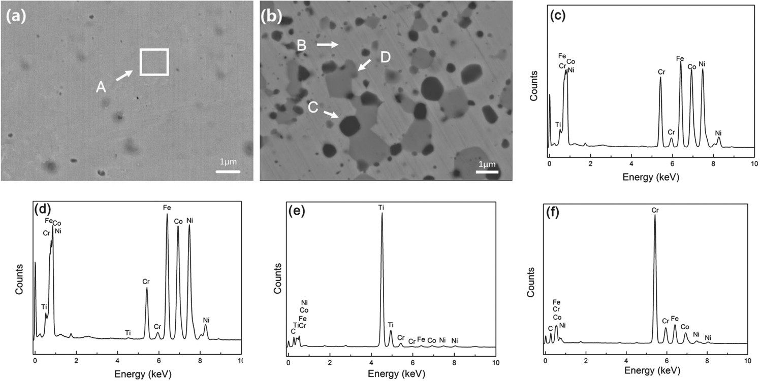
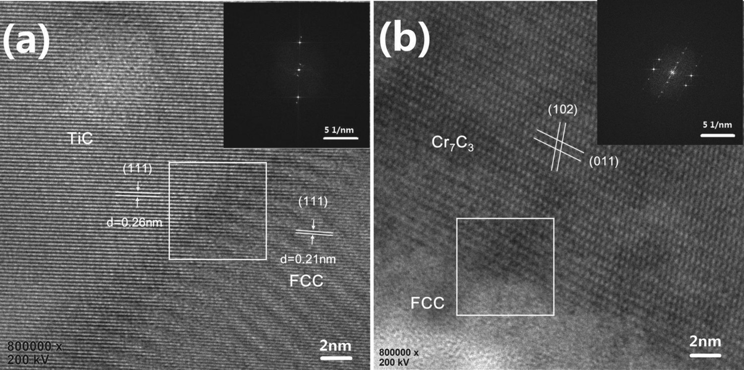
To further investigate the microstructure and phase composition of the CoCrFeNiTi0.2C0.2 green bodies sintered at 1200°C for 1 h, a thin foil sample was prepared by ion milling for TEM observation. Figure 5 shows the bright field TEM image and selected area electron diffraction (SAED) patterns of the sintered CoCrFeNiTi0.2C0.2. Three kinds of grains with various contrasts and morphologies are observed in the sintered bodies (marked as grains 1, 2 and 3). The grains 1, 2 and 3 exhibit a similar appearance and chemical composition with the C, D and B grains shown in Figure 4(b), respectively. Moreover, the corresponding SAED patterns (Figure 5(b–d)) suggested that the grains 1, 2 and 3 were TiC phase with a B1-NaCl structure (a = 0.433 nm), Cr7C3 phase with an orthorhombic structure (a = 0.453 nm, b = 0.701 nm, c = 1.214 nm) and CoCrFeNi solid solution with an FCC structure (a = 0.360 nm), respectively. The TEM observations further confirmed the formation of TiC and Cr7C3 type carbides in sintered green bodies which were in consent with the XRD and SEM results, referring to Figures 3 and 4. Figure 6 shows the HRTEM images of the interface between the formed phases in CoCrFeNiTi0.2C0.2 green bodies sintered at 1200°C for 1 h. Referring to Figure 6(a), the interplanar spacing for upper left grain and lower right grain were 0.26 and 0.21 nm, respectively, which was corresponded to (1 1 1) plane of TiC and the FCC structured solid solution phase. Fast Fourier transform (inset in Figure 6(a)) suggested that TiC(111) was almost paralleled to FCC(111) with a small angle difference (∼2.2o). The results indicated that the interfacial microstructure between TiC and the FCC structured matrix was a semi-coherent interface, since they had a relatively small crystal mismatch between (111) plane. The interplanar spacing for upper right grain in Figure 6(b) was corresponded to Cr7C3 (102) and (011) lattice, which again proved the formation of Cr7C3 type carbide. The interface between Cr7C3 and the matrix was likely a noncoherent interface caused by their large differences in interplanar spacing. No other compound was formed at the interface between matrix and carbides, referring to Figure 6.
TEM image (a) and SAED patterns of CoCrFeNiTi0.2C0.2 composite sintered at 1200°C for 1 h, (b) grain 1 taken along [001]TiC, (c) grain 2 taken along [010]Cr7C3 and (d) grain 3 taken along [011]FCC. HRTEM image of the interface between TiC type carbide and matrix (a) and Cr7C3 type carbide and matrix (b) for CoCrFeNiTi0.2C0.2 composite sintered at 1200°C for 1 h.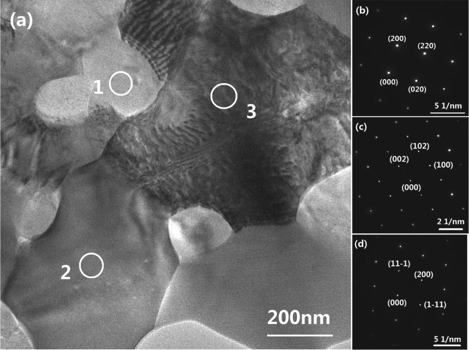
In addition, a flake twin structure was observed in CoCrFeNi solid solution grains, shown in Figure 7. The width of flake twin was in the range of 35–100 nm with a twinning plane of (111). The formation of twin structure in the fabrication process of the composites indicated that the CoCrFeNi phase might have low stock fault energy (SFE). Since the pre-alloyed CoCrFeNi powders were severe plastic deformed during milling and then recrystallised at elevated temperature during sintering stage, disordering of (111) plane of CoCrFeNi phase with low SFE was easily occurred during recrystallising and consequently the formation of annealing twin structure, referring to Figure 7. The presence of twins usually serves to impede dislocation motion and induce strengthening of the material [25,26].
Twin structure in matrix of CoCrFeNiTi0.2C0.2 (a) and the corresponding SAED pattern (b)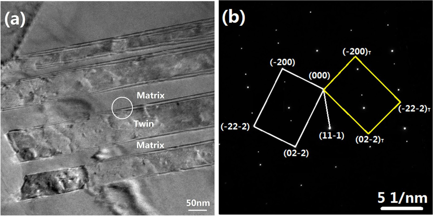
Figure 8 shows magnetic hysteresis curves versus an applied magnetic field for the CoCrFeNiTi0.2C0.2 composite at different states. The specific saturation magnetisation (Ms) reached 72.1, 54.8 and 61.7 emu g−1, respectively for the CoCrFeNiTi0.2C0.2 composite measured at initial state (mixed powders), milled state and sintered state. The decrease in specific saturation magnetisation for milled and sintered powders is probably attributed to the increase in microdefect density. In addition, the average coercivity (Hc) and remanence ratio (residual magnetisation/saturation magnetisation) of the sintered CoCrFeNiTi0.2C0.2 bulks reached 8.0 Oe and 1.7%, respectively which are kept in low values. For soft-magnetic materials, the higher saturated magnetisation and the smaller coercivity indicated the better soft-magnetic properties. It was found that the soft-magnetic properties of the CoCrFeNiTi0.2C0.2 composite were better than some of the reported HEAs, such as TiFeNiCrCo [10], FeSiBAlNiCe [27] and FeSiBAlNiAg [28]. Therefore, the CoCrFeNiTi0.2C0.2 composite is a promising soft-magnetic material.
Magnetic hysteresis loop of the CoCrFeNiTi0.2C0.2 composite measured at a different state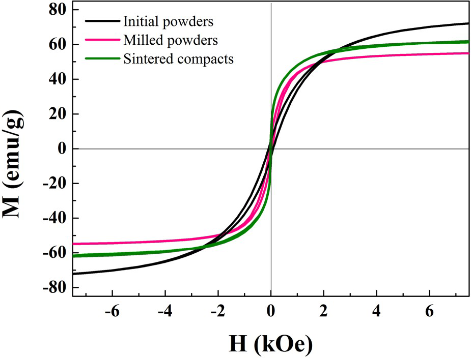
Mechanical properties of sintered CoCrFeNiTi0.2C0.2 composite
The relative density and Vickers hardness were measured for the sintered CoCrFeNi and CoCrFeNiTi0.2C0.2 composite green bodies. The relative density and Vickers hardness of the milled powders after hot pressing sintered at 1200°C for 1 h reached 98.6%, 124 HV and 98.4%, 501 HV, respectively. The low hardness of CoCrFeNi alloy is comparable to that of the reported CoCrFeNi alloy prepared by arc melting [12], which is mainly caused by the weak solid solution hardening effect in this HEA. The hardness of CoCrFeNiTi0.2C0.2 was ∼4 times the CoCrFeNi alloy, which was probably caused by the formation of hard carbides (i.e. TiC and Cr7C3 type carbides) in the sintered composite. The compressive stress–strain curves of the rod samples were tested and a typical result is shown in Figure 9. It was found that the sintered composite possesses excellent compressive mechanical properties with high yield strength (i.e. 1.12 GPa), which was about twice the strength of CoCrFeNi alloy and extremely high ultimate strength (i.e. 2.55 GPa). Moreover, the CoCrFeNiTi0.2C0.2 composite also exhibited large ductility of 50.3% under uniaxial compression state, referring to Figure 9. In general, mechanical properties of high entropy-based composites are directly related with the size, distribution, mechanical properties and the coherency of the precipitates in the matrix [16]. Between the formed reinforcement phases in CoCrFeNiTi0.2C0.2, TiC have the highest hardness of ≈3400 HV, while the Cr7C3 carbide reaches 1600 HV [29]. It is assumed that both of the formed nano-sized TiC and micro-sized Cr7C3 homogeneously dispersed in the matrix, led to the increase of properties. Additionally, the semi-coherent interface structure between the spherical TiC phase and matrix (Figure 6(a)) and the twining of the FCC solid solution (Figure 7) would have a positive influence on mechanical properties, especially the ductility of the material. The results suggest that the mechanically alloyed CoCrFeNiTi0.2C0.2 can be fully densified with high strength and hardness, which will be a promising material for fabricating hot-working tools and dies.
Compressive stress–strain curves of CoCrFeNi and CoCrFeNiTi0.2C0.2 composite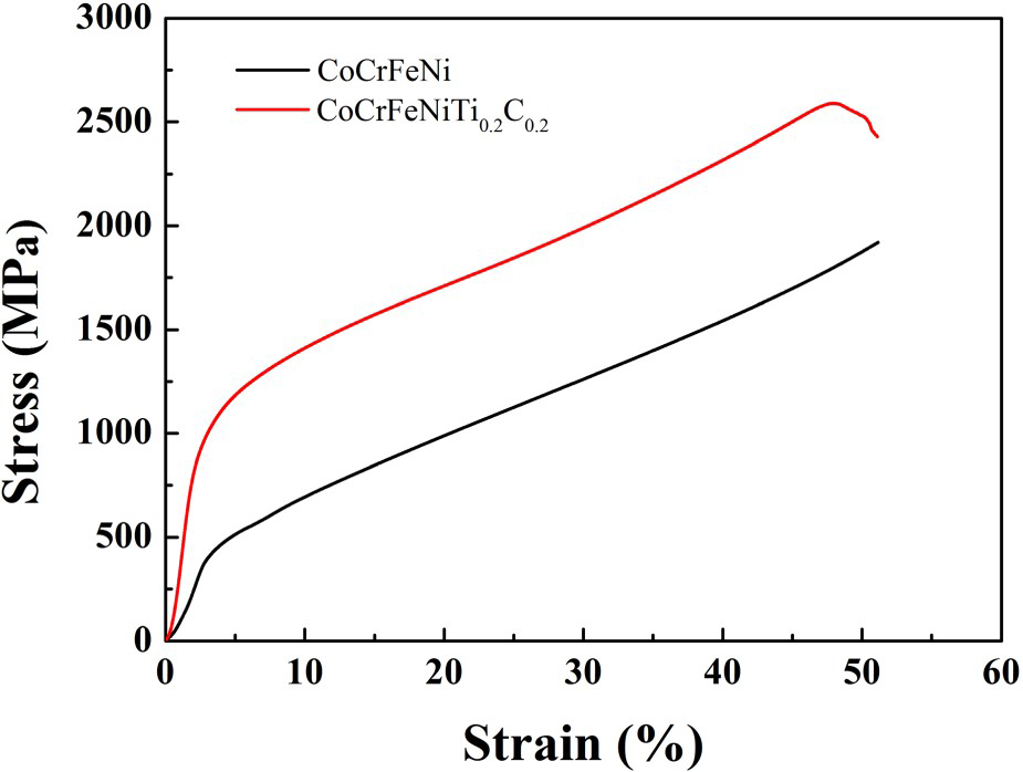
Conclusions
Titanium carbide reinforced CoCrFeNi high-entropy alloy has been successfully synthesised by mechanical alloying and subsequently hot pressing sintering. The characterisation of the milled powders and sintered green bodies has been systematically studied. The following findings were obtained as a result:
The Co, Cr, Fe and Ni powders passed through a deformation – cold welding–crushing – cold welding–crushing process during ball milling, and a single-phase CoCrFeNi solid solution with FCC structure was obtained after milled for 10 h. Nano-sized TiC and micron-sized Cr7C3 carbides were formed and embedded in the CoCrFeNi solid solution dispersedly after hot pressing sintered at 1200°C for 1 h. The hardness and compressive fracture strength of the sintered green bodies were 501 HV and 2.55 GPa, respectively, which could be ascribed to the presence of in-situ formed TiC and Cr7C3 type carbides in this composite.
It is emphasised that the results presented here only provide a strengthen method with controllable carbide for the single-phase HEAs. More studies should be further investigated, such as the effect of C, Ti content and milling parameters on phase composition, the coarsening behaviour of the carbides, etc.
Footnotes
Disclosure statement
No potential conflict of interest was reported by the authors.