
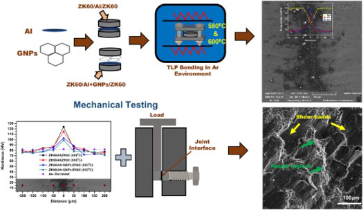
Abstract
Transient liquid phase bonding of ZK60 magnesium alloy was performed by incorporating aluminium foil as an interlayer, unaided and in combination with graphene nanoplatelets. The solitary incorporation of aluminium foil increased the shear strength of magnesium alloy in comparison to the addition of graphene nanoplatelets with aluminium foil. The fractured surfaces revealed a mixed-mode fracture while the hardness profile across the interface showed the increase in hardness in the bonded region, which was due to the formation of Al12Mg17 intermetallic.
GRAPHICAL ABSTRACT
Introduction
Wrought magnesium (Mg) alloys offer a good combination of mechanical properties and other attributes, including low density, corrosion resistance, shock absorbance, and vibration properties [1]. Owing to the attractive set of properties, Mg alloys are used in various structural applications, including aerospace, automotive, communication, electronics, and materials handling equipment. The major drawbacks of Mg alloys are their limited ductility, low stiffness, poor workability due to their close-packed hexagonal structure, and reduction in mechanical properties at elevated temperatures.
Various techniques have been employed for the joining of Mg alloys to broaden their applications, including fusion welding, friction stir welding, brazing, friction stir spot welding, laser beam welding, and transient liquid phase (TLP) bonding [2-6]. Among a variety of compositions of wrought Mg alloys, ZK60 alloy contains zinc as a major alloying element and, in general, has a wide liquidus-solidus temperature range; the latter results in liquation cracking in the partially melted zone and solidification cracking in the fusion zone during welding [7].
TLP bonding is preferred over fusion welding in joining Mg alloys as it involves low temperatures [8,9]. A thin interlayer is used in TLP bonding to form a low melting point eutectic. TLP bonding is also used to join metal matrix composites with minimum deformation and changes in joint microstructure [10]. The dedicated studies have been performed for TLP bonding of Mg alloys using different processing parameters and interlayer materials for improved interfacial performance, including nickel, copper, silver, and aluminium [11-14].
Recently, it has been reported that graphene nanoreinforcements significantly improve the mechanical performance of metal matrix composites due to their excellent mechanical, electronic, and physical properties [15,16]. For example, Zhang et al. [17] showed the improvement in the mechanical properties of the fusion-welded AZ31 Mg alloy after the incorporation of graphene nanoplatelets (GNPs). However, the effect of incorporating GNPs in combination with TLP bonding on the quality of interfacial bonding has not yet been investigated.
In the present investigation, the TLP bonding of ZK60 Mg alloy was carried out using aluminium (Al) interlayer combined with GNPs, which has not been reported earlier. The underlying aim is to investigate the effect of a nanometer-scale material, i.e. GNPs, on the interfacial strength of the bonded Mg alloy. Sandwich structures of Mg alloy with the addition of solitary aluminium and aluminium combined with GNPs, i.e. (a) ZK60/Al/ZK60 and (b) ZK60/Al + GNPs/ZK60, were prepared by TLP bonding at two different bonding temperatures in a liquid–solid two-phase region. The quality of the produced joints was examined using electron microscopy while the distribution of Al and Mg across the interface was studied using energy dispersive spectroscopy; the presence of different phases at the interface was studied by X-ray diffraction. The mechanical properties including shear strength of TLP bonded structures and hardness profile across the interface were evaluated along with the observation of the morphology of the fractured surface.
Experimental
Materials
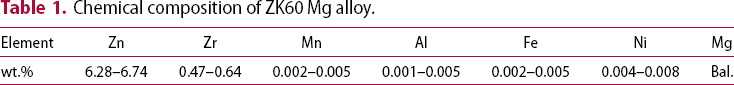
Chemical composition of ZK60 Mg alloy.
Manufacturing
For the manufacturing of TLP bonded structures, discs of thickness 3 mm were cut from a 30 mm diameter rod of ZK60 using a slow speed cutter (Buehler Isomet, ITW Company, Illinois). Al foil along with GNPs was used as an interlayer between two Mg discs (ZK60/Al + GNPs/ZK60). For reference, Al foil was used individually as an interlayer between the two Mg discs (ZK60/Al/ZK60). For TLP bonding, the mating surfaces were ground upto a 2000 grit finish. Subsequently, the discs were degreased and cleaned with acetone. In parallel, a pre-determined quantity, i.e. 50 mg of GNPs was dispersed in 50 mL of ethanol and ultrasonicated for 15 min at room temperature for their uniform dispersion using a probe sonicator (Hielscher UP400S, Teltow, Germany). The prepared suspension of GNP-ethanol was then dropped on Al foil and dried in an oven to evaporate ethanol. GNP-loaded Al foil was sandwiched between two magnesium discs and compressed under a hydraulic press (Specac Hydraulic Press, Kent, UK) at 125 MPa to establish initial contact between the mating surfaces. The pressed ZK60 alloy discs containing Al + GNPs were then pressed in a custom-made pressing fixture to avoid detachment of ZK60 discs. Finally, the samples were placed in a tube furnace (KJ1600 G, Zhengzhou Kejia Furnace Company, China) under argon (Ar) atmosphere and heated at two different temperatures of 580 and 600°C, respectively, at a heating rate of 5°C min–1 for 90 min followed by furnace cooling. The same experiment was repeated by incorporating Al interlayer alone between the mating surfaces of ZK60 alloy discs. Figure 1 represents the schematic illustration of the experimental procedure.
Schematic illustration showing the procedure of manufacturing TLP bonded sandwich structures by incorporating Al foil and GNPs.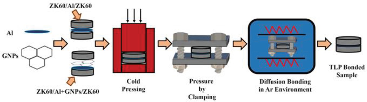
Characterisation
After TLP bonding, sandwiched discs of ZK60 were cut perpendicular to the bonding interface using a slow-speed diamond cutter. Subsequently, the specimens were subjected to standard metallographic procedures, including grinding and polishing using a grinding/polishing machine (Metkon Forcipol 2V, Metkon Instruments Inc.). The cross-sections of TLP bonded ZK60 alloy and fractured surfaces were examined in secondary electron imaging mode by field emission gun scanning electron microscope (FEG-SEM)(MIRA-III, FEG-SEM, Tescan Orsay Holding, Czech Republic) at an accelerating voltage of 20 kV. The fracture surface of specimens was also observed using FEG-SEM. Chemical composition (line scan) of TLP bonded interface and matrix was determined using energy dispersive spectroscopy (EDS) (X-MaxN Silicon Drift Detector, Oxford Instruments, UK). X-ray diffraction (XRD) of fractured samples was performed to identify the presence of different phases and the emergence of any new phase after TLP bonding in 2θ range of 20° to 80° using an X-ray diffractometer (Bruker D8, Bruker Corporation, Massachusetts). After polishing the surface of samples, the hardness profile across the interface was acquired by Vickers micro-hardness tester (HMV – G21, Shimadzu, Japan) equipped with a pyramid-shaped diamond indenter to produce indentation at a load of 25 gf and dwell time of 30 s. An average of 5 hardness readings was taken from bulk material to the interface for the specimen. The shear test was carried out on a universal tensile testing machine (WDW-30, Jinan Testing Equipment, Jinan, China) using a custom-made fixture at a crosshead speed of 0.5 × mm min–1 at room temperature. Three samples of each bonding condition having dimensions 20 × 6 × 3 mm were cut using a slow-speed cutter for shear testing. Finally, the fractography of fractured surfaces of the shear test samples bonded at different temperatures was characterised by FEG-SEM.
Results and discussion
Microstructure
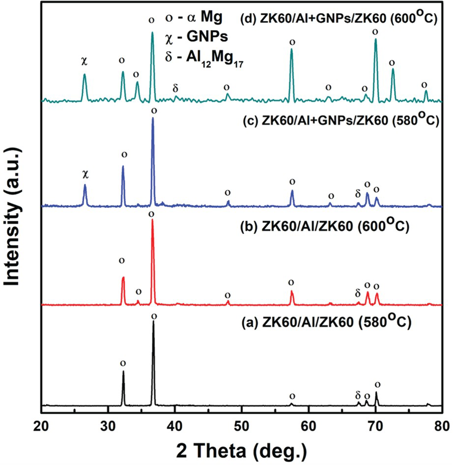
The cross-sectional images from the interface of ZK60/Al/ZK60 and ZK60/Al + GNPs/ZK60, bonded at 580 and 600°C, are shown in Figure 2. The specimens bonded with Al interlayer showed the complete diffusion of Al along the interface resulting in a narrow bonded region of width <10 µm (Figure 2(a,b)). Al interlayer was melted and re-solidified to form a metallurgical bond. Mg–Zn phase diagram predicts partial melting of Mg in the liquid–solid two-phase region at the bonding temperatures. The eutectic temperature between Mg and Al is 437°C [18,19], while the temperatures under investigation are high enough (580 and 600°C) for a thin Al interlayer to completely dissolve/diffuse along with the interface and into the grain boundaries. According to Al–Mg binary phase diagram (as shown in Figure 4 [19]), with an increase in temperature, the concentrated Al at the interface diffuse along the Mg side and Al12Mg17 intermetallic phase is reported to form at the interface as a result of reaction 17Mg + 12Al → Al12Mg17 [18,20]. The compositional profiles (Figure 3(a,b)) across the interface show the distribution of Mg and Al. The diffusion of Al into bulk material along grain boundaries was increased at a higher temperature of 600 than 580°C. The concentration of Mg in diffusion bonded regions lowers to 62.33 wt-% for TLP bonding at 580°C while it decreases to 40 wt-% for bonding at 600°C, which is due to the presence of Al at the interface. Owing to concentrated Al at the interface, the eutectic zone has a greater amount of Al than the isothermal solidification zone, and Al12Mg17 compound formed during the cooling due to eutectic reaction, i.e. L (liquid) → Al12Mg17 + α-Mg [10]. Since isothermal solidification occurs when the composition of Mg reaches about XR of 66.7 wt-%, as shown in Figure 4. XRD results (Figure 5) of the fracture surfaces confirm the formation of Al12Mg17 phase. Similar findings have been reported in the previous studies [10,18,20,21]. Also, the stoichiometric ratios of Al and Mg at the interface matches with the Al12Mg17 phase [10,18].
SEM images of TLP bonded ZK60 magnesium alloy at two different temperatures and containing aluminium foil alone and in combination with graphene nanoplatelets: ZK60/Al/ZK60 at (a) 580°C and (b) 600°C, and ZK60/Al + GNPs/ZK60 at (c) 580°C and (d) 600°C. Black arrows indicate interface and white arrows show grain boundaries. EDS line scan elemental analysis of TLP bonded ZK60 magnesium alloy at two different temperatures and containing aluminium foil alone and in combination with graphene nanoplatelets; magnesium decreases at the interface while aluminium and carbon (graphene nanoplatelets) increase. Al–Mg binary phase diagram [19]. XRD patterns of fractured surfaces of (a,b) ZK60/Al/ZK60 and (c,d) ZK60/Al + GNPs/ZK60 bonded at 580 and 600°C showing the presence of α-Mg, Al12Mg17, and GNPs.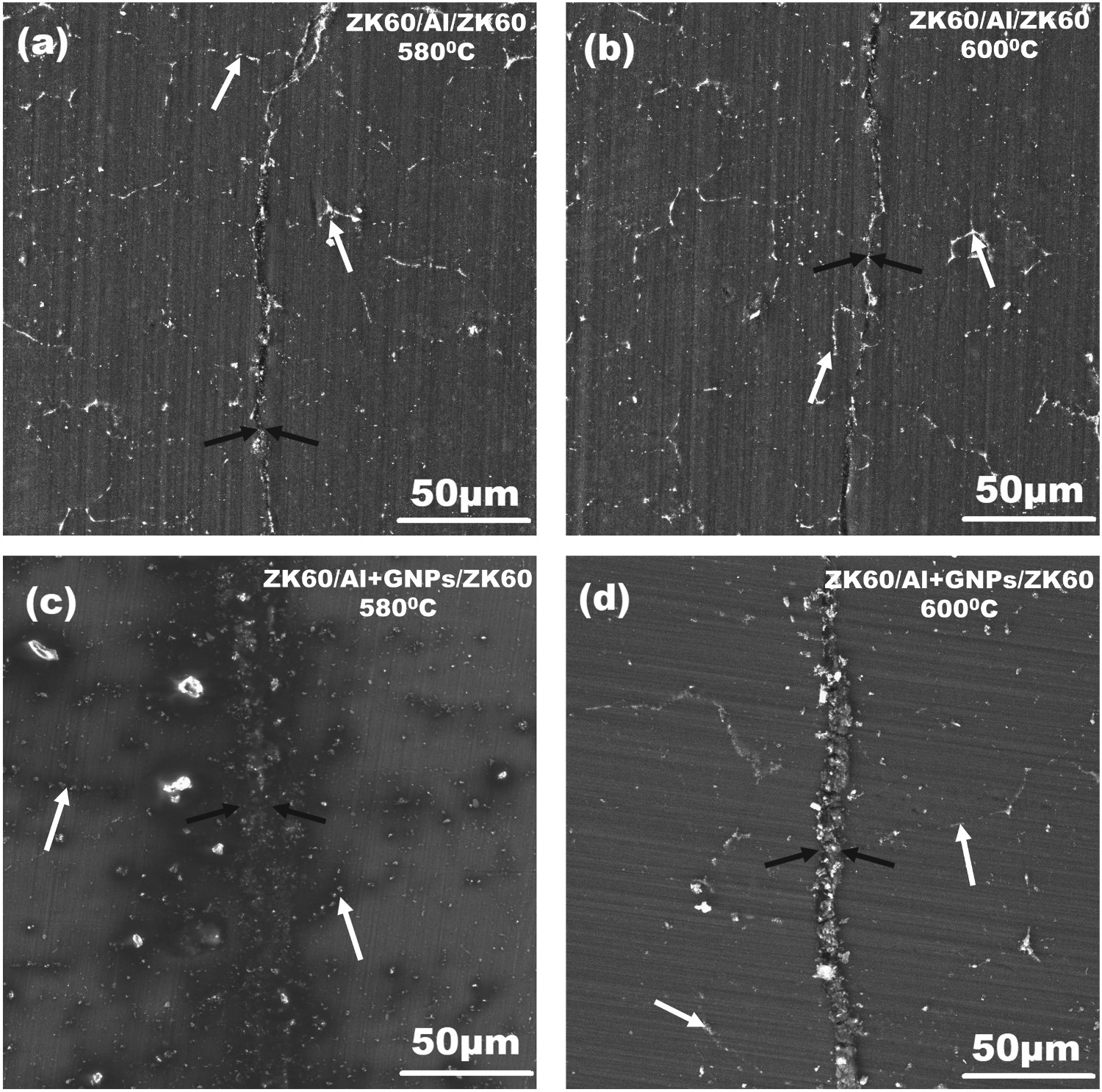
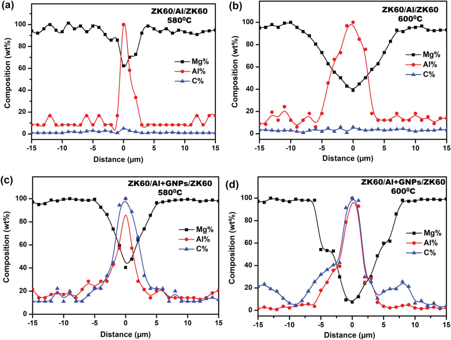

In specimens bonded with Al and GNPs at 580°C, the diffusion was suppressed along with the interface, resulting in a bond of width ∼10 µm (Figure 2(c)), which is still narrow compared to the reported in the recent study conducted by Dehnavi and Bakhtiari [22]. However, the width of the joint expanded with the increase in bonding temperature [18]. At 600°C, the cluster formation can be seen at the interface. GNPs suppress diffusion between Al and Mg, and the width of the joint is ∼15 µm; grain coarsening was also observed (Figure 2(d)). This coarsening of grains causes the decrement of mechanical properties [12,21]. Owing to a significant difference in the melting points of constituents, GNPs acted as a barrier for the diffusion of Al and Mg atoms [23]. SEM images (Figure 2(c,d)) of specimens containing Al + GNPs revealed intermixing of GNPs with interlayer and showed a higher concentration of Al and C at the interface while Mg decreased to 27wt-% and 8wt-% at 580 and 600°C, respectively (Figure 3(c,d)), which may be due to suppression in diffusion by GNPs [24].
XRD analysis
XRD analysis (Figure 5) of fractured surfaces of ZK60/Al/ZK60 indicated the presence of α-Mg as the major phase while diffracted peaks from GNPs were also observed in ZK60/Al + GNPs/ZK60. No indication of carbide formation was observed, especially Al4C3, which may be due to low temperature for the reaction of GNPs with Al and also because GNPs acted as diffusion barrier [23]. However, the formation of the Al12Mg17 phase was observed, which led to high hardness at the interface compared to bulk metal. It also induced brittleness in fracture and affected the mechanical properties. Al-Mg binary phase diagram (Figure 4) supports the formation of Al12Mg17 [18,19]. In case of ZK60/Al/ZK60, the narrow-bonded region (Figure 2(a,b)) results in the lower Al12Mg17 [21], which may account for the increase in the interfacial shear strength as compared to ZK60/Al + GNPs/ZK60.
Mechanical properties of composites
Hardness
The hardness of as-received ZK60 alloy in as-extruded condition was measured to be 82 ± 1HV. After diffusion bonding, the hardness of the bulk material was found to be 78 ± 2HV, which increased towards the joint (Figure 6). This slight decrease in hardness at base metal is due to recrystallisation at the bonding temperature. At joint, the hardness values of ZK60/Al/ZK60 bonded at 580 and 600°C were found to be 124 ± 3 and 115 ± 2 HV, respectively. This increment in the hardness values is due to the concentrated Al at the joint interface which promotes the formation of Al12Mg17, as indicated by XRD (Figure 5); as also found in the literature [18,21]. Hardness values of samples containing Al + GNPs indicated the average hardness value of 75.6 ± 3HV at the base metal and 100 ± 3HV at the interface (Figure 6). The decrease in the hardness at the interface is due to suppression in the formation of Al12Mg17 due to GNPs because these acted as a diffusion barrier [23]. Also, it is well understood that the hardness is a function of microstructure, and SEM micrograph (Figure 2(d)) shows grain coarsening which also causes the reduction in the hardness.
Vickers hardness profiles of TLP bonded ZK60 magnesium alloy across the interface at two different temperatures containing aluminium foil alone and in combination with graphene nanoplatelets. Hardness values increase at the interface due to the formation of Al12Mg17 intermetallic; the effect is more in specimens containing solitary aluminium.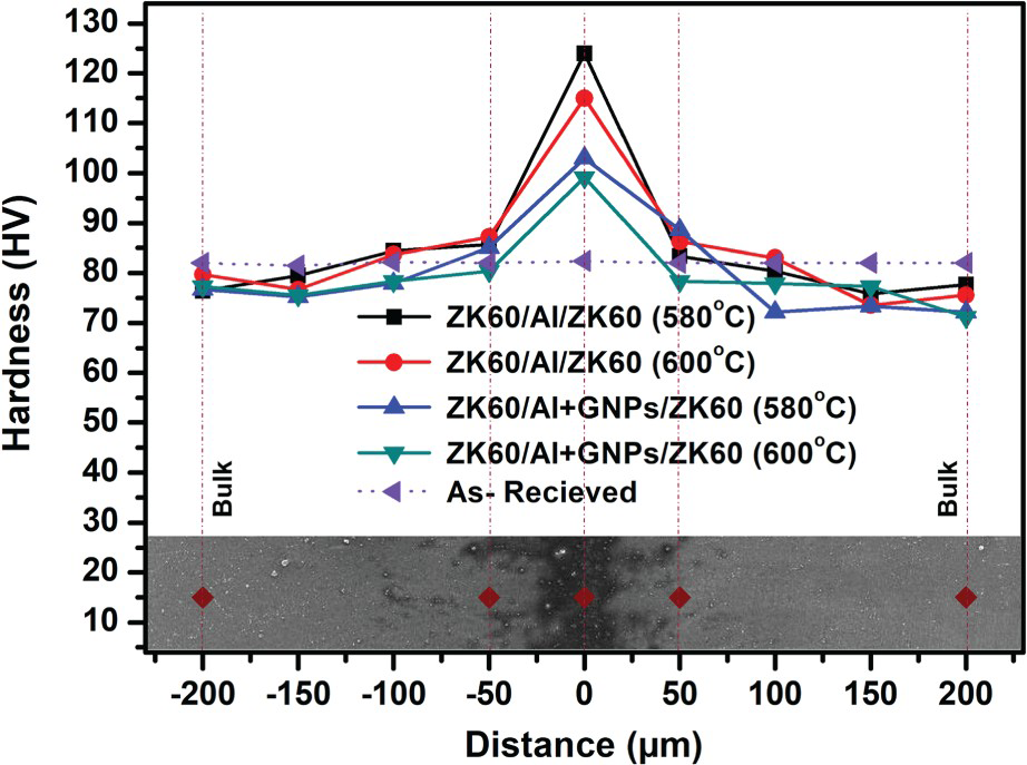
Shear strength
Figure 7(a) shows representative shear stress–strain curves of specimens, while Figure 7(b) shows the maximum shear strength values at the two TLP bonding temperatures. It can be seen that the shear strength values of ZK60/Al/ZK60 are higher than ZK60/Al + GNPs/ZK60. Moreover, the bonding temperature of 580°C offered better values than 600°C. Shear strength of the samples containing GNPs was found to be 10.2 ± 0.5MPa and 6.7 ± 0.4 MPa at 580 and 600°C, while 12.2 ± 0.6MPa and 10.8 ± 0.3 MPa, were observed for Al interlayer, respectively. Similarly, the strain-to-fracture is higher for samples without GNPs (Figure 7(a)) and for samples bonded at 580°C. It can be expected that the formation of localised nanocomposites due to the incorporation of GNPs reduced the local ductility, while the local rise in stiffness and strength due to the formation of nanocomposites was nullified by the emergence of Al12Mg17, which was found excessive at 600°C [14,18]. Moreover, GNPs were used than single-layer graphene; therefore, the shearing of graphene layers in GNPs also accounted for the lower shear strength [25,26]. GNPs also act as a diffusion barrier layer at the interface, which results in the suppression of diffusion between Al and Mg (Figure 3(c,d)) thus degrading the mechanical properties of the TLP bonded joint [24]. Fractographs in Figure 8 (discussed below) support the brittle behaviour of specimens containing GNPs.
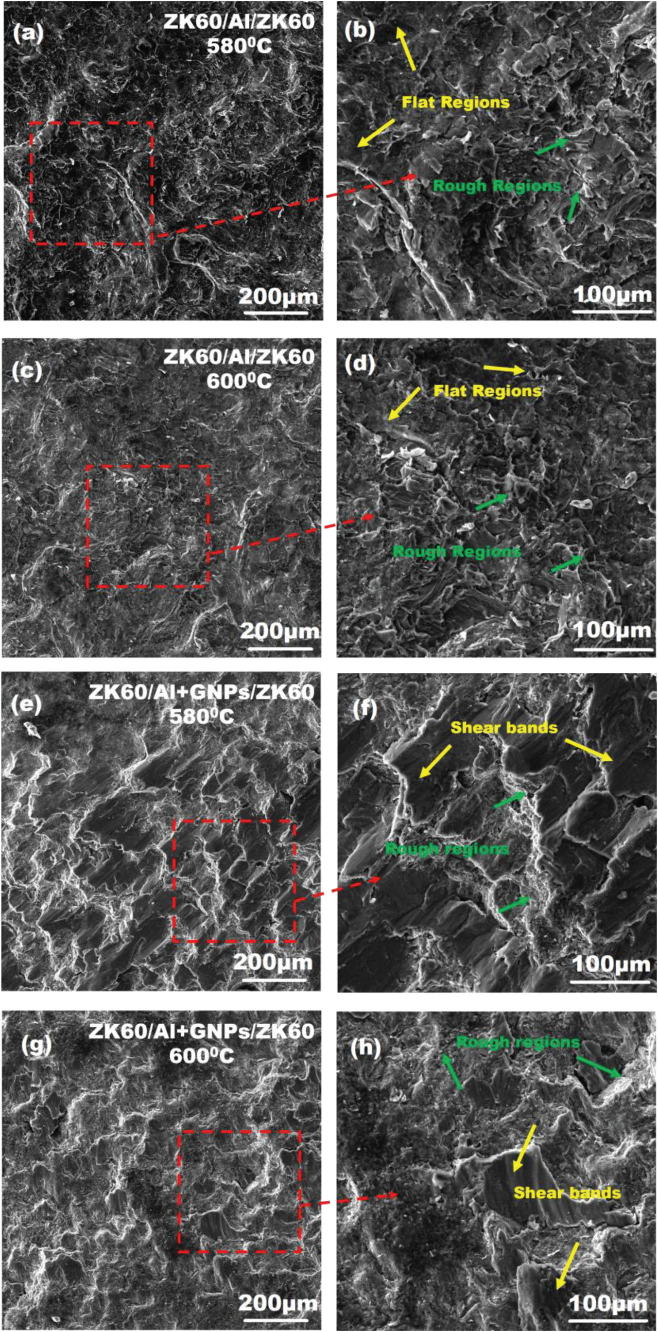
(a) Shear stress–strain curves of ZK60 magnesium alloy specimens TLP bonded at two different temperatures containing aluminium foil alone and in combination with graphene nanoplatelets, (b) graphs showing shear strength values as a function of bonding temperatures and type of interlayers. Fractographs of TLP bonded ZK60 magnesium alloy at two different temperatures and containing aluminium foil alone and in combination with graphene nanoplatelets: ZK60/Al/ZK60 at (a,b) 580°C and (c, d) 600°C, and ZK60/Al + GNPs/ZK60 at (e,f) 580°C and (g, h) 600°C.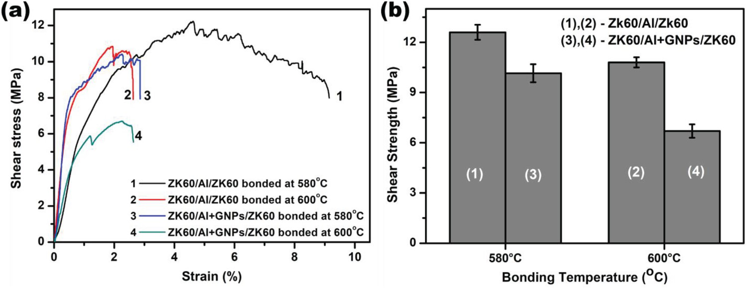
Nevertheless, if compared to the shear strength (i.e. 5 MPa) of Mg/Al sample bonded at 430°C without interlayer in a different study [18], the strength values obtained in the present study are considerably higher and also comparable with the work of Saremi et al. [21].
Fractography
SEM observation of fractured surfaces of ZK60/Al/ZK60 indicated mixed fracture mode (Figure 8): the flat region represented the brittle failure while the rough region represented the presence of plastic deformation. The plastic deformation was observed due to the dissolution of the Al interlayer, which was the reason for ductile behaviour [10]. Fractographs of ZK60/Al/ZK60 bonded at 580°C in Figure 8(a,b) indicated higher plastic deformation than the sample bonded at 600°C (Figure 7(a)); the later flatter surfaces indicated lesser deformation, which was probably due to the large quantity of brittle Al12Mg17 at the interface (Figure 8(c,d)) [18,20]. The brittle behaviour may also be due to the HCP structure of Mg having parallel slip planes. Fractographs of ZK60/Al + GNPs/ZK60 bonded at 580°C indicated mixed-mode fracture; the facets represent brittle behaviour while rougher regions around the facets indicate plastic deformation. This transition to mixed-mode fracture was also recently observed by Munir et al. in Mg-GNPs composites [15]. Grains can also be seen elongated in the direction of deformation, forming shear bands (Figure 8(e,f)). The sliding of stacked layers of GNPs also causes the initiation of cracks [25]. Fractographs of ZK60/Al + GNPs/ZK60 bonded at 600°C indicated increased flat regions representing even lower strain-to-fracture, which may be due to suppressed diffusion because of GNPs and the formation of Al12Mg17 (Figure 8(g,h)) [18,24]; the micrograph in Figure 2(d) also supports lower mechanical properties.
Conclusions
Transient liquid phase bonding technique was used for the joining of ZK60 Mg alloy using Al foil and Al + GNPs as interlayers. Two different temperatures of 580 and 600°C were chosen for the bonding process optimisation while keeping a constant holding time of 90 min under the Ar atmosphere.
Scanning electron microscopy and energy dispersive spectroscopy results showed partial melting along with the interface and diffusion of Al along grain boundaries in the specimens bonded with Al interlayer. While, in the case of specimens bonded using Al + GNPs, the diffusion between Al and Mg atoms was suppressed by the GNPs. Vickers hardness testing results showed a significant rise in values at the interface, which was due to the formation of Al12Mg17 intermetallic, as confirmed by X-ray diffraction analysis. However, higher hardness values were observed for specimens containing individually incorporated Al than dual addition with GNPs. The shear strength of transient liquid phase bonded samples using solitary Al interlayer also showed higher values than those containing Al + GNPs. It can be inferred that GNPs suppressed the diffusion process, which accounts for the poor mechanical performance of interfacial bonding after adding Al with GNPs, and the effect of GNPs was diminished due to the formation of a hard Al12Mg17 intermetallic. Nevertheless, individually incorporated Al showed the maximum shear strength of 12.6 ± 0.5 MPa after bonding at 580°C. Fractographs of the bonded samples showed a mixed-mode fracture revealing flat facets and rough regions, thus indicating a combination of ductile and brittle failure.
Footnotes
Acknowledgements
The authors would like to acknowledge Tahir Mahmood, Mahmood Khan, and Muhammad Ibrahim for assisting in FESEM, EDS, XRD, and hardness testing.
Disclosure statement
No potential conflict of interest was reported by the author(s).