
Abstract
5A02 aluminium alloy was joined by transient liquid phase (TLP) bonding using the two-step heating process as follows: the faying area was first heated to 600°C and kept for 5 s and then cooled down to 595°C and kept for 3 min. The microstructure and properties of the joint were investigated and compared with that of conventional TLP bond at 595°C for 3 min. The results show that the two-step heating process can produce a wave bond line that is different from the planar interface associated with conventional TLP bonding at a constant temperature. The defects at the bond line are greatly reduced, and metal to metal contacts are established along the wave bond line using the two-step heating process. Therefore, the tensile strength and bending ductility of the joint are dramatically improved.
Introduction
Aluminium can form an oxide film at exposed surface. The oxide film is very adherent, chemically stable and insoluble in the aluminium substrate at all temperatures and so prevents full metal to metal contact from being established at the joint interface. Therefore, aluminium and its alloys are difficult to diffusion bond.1 Transient liquid phase (TLP) bonding is an important variation of diffusion bonding that has the potential to overcome the oxide problem. A liquid phase is formed during the bonding process and undermines and reduces the substrate oxide film. Then, the oxide is highly fragmented after bonding, and so thin undermined oxides do not degrade the mechanical properties of the joint.2 In the TLP bonding of aluminium and its alloys, a copper foil interlayer is inserted between the faying surfaces of components in a butt joint. The assembly is then heated to a temperature in the vicinity of the Al–Cu eutectic temperature. The diffusion of copper into the aluminium substrate induces melting, and the liquid solidifies isothermally as homogenisation occurs and the liquidus temperature rises.3 Although the formation of the liquid phase can assist in the disruption of the oxide film, the oxide remains as a stable phase and is redistributed in front of the moving solid/liquid interface. During isothermal solidification, any insoluble oxide particles and impurities trapped in the liquid phase are pushed forward by the advancing solid/liquid interface. Eventually, these particles agglomerate at the bond line and also prevent metal to metal contact from being fully established. In addition, local equilibrium is maintained at the solid/liquid interface throughout isothermal solidification, and a flat interface is formed in the final joint. Therefore, the fairly flat interface contains oxide particles and impurities that detrimentally affect the mechanical properties of the joint.1, 3
Temperature gradient TLP bonding is a new approach capable of producing bond lines with various morphologies (e.g. sinusoidal to fully dendritic) by imposing a temperature gradient across the bond during joining.4– 9 The formation of a non-planar interface can result in a better distribution of oxides and impurities at the bond. Bond strengths are increased possibly due to the higher metal to metal contact along the non-planar interfaces as compared to the planar interfaces associated with conventional TLP bonding. Using this method, reliable bonds with shear strength as high as those of base materials have been produced in aluminium alloys.
TLP bonding using two-step heating process is another ingenious development in producing homogenous joints free of bond line.10– 12 In this process, the interlayer is first heated up to a high temperature and held for a few seconds and then cooled down to a low temperature and held for a few minutes. The liquid phase is formed at the high temperature and begins to solidify at the low temperature. Owing to a fall of temperature, constitutional supercooling is formed, and solid/liquid interface becomes unstable and adopts a convoluted shape. Different from the unidirectional interface migration during temperature gradient TLP bonding, the two non-planar interfaces move in opposite directions and meet at the middle of the liquid phase. Then, high angle grain boundaries are combined, and a homogenous joint free of bond line is formed. Using this process, strong and ductile joints have been produced in steels, and the oxide and impurities are decreased by controlling the two-step heating process.10
In this paper, a two-step heating process was applied to TLP bond 5A02 aluminium alloy using aluminium base interlayer. The microstructures and properties of the joints were studied, and the microstructure evolution in TLP bonding by using two-step heating process was also discussed.
Experimental
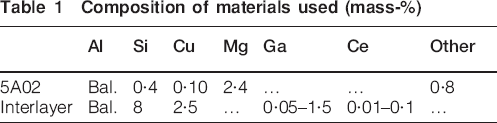
The base metal was 5A02 (China standard) aluminium pipe, which was used for SF6 potential transformer conductor tube. Its outside diameter and thickness were 60 and 8 mm respectively. The interlayer metal was Al base foil in the form of washer with outside diameter of 60 mm, inside diameter of 44 mm and thickness of 80 μm. Their composition in weight per cent is given in Table 1. The melting points of 5A02 and interlayer were 621 and 540°C respectively.
Composition of materials used (mass-%)
The faying surface was machined to an Ra of 63·5 μm and degreased in alcohol. Two pipes were mounted on a loading device. After arranging the interlayer between two pipes, it was pressed for axial direction and induction heated. A chromel/type K thermocouple was spot welded onto the outside edges of the test pipe for temperature control. During induction heating, the faying area was covered by argon flux to prevent the oxidation. The sketch of joining apparatus and assembly of pipes is shown in Fig. 1.
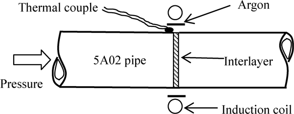
Sketch of joining apparatus and assembly of pipes
The bonding experiment was carried out at 595°C×3 min for conventional TLP bonding process and 600°C×5 s–595°C×3 min for two-step heating process. A 7 MPa bonding pressure was applied for both bonding processes. The joints were cross-sectioned and analysed with scanning electron microscope (SEM) and energy dispersive X-ray spectroscopy (EDX). Before SEM and EDX, the cross-sections were first ground with SiC paper down to grade 1000 and then electropolished in an electrolyte consisting of 20% perchloric acid and 80% alcohol. The mechanical properties of the joints were obtained by tensile and bending tests. The test samples were taken from the welded pipe with reference to ISO 4136 and 5173. The shape and dimensions of a sample for tensile and bending tests are shown in Figs. 2 and 3 respectively. Both tests were carried out on a universal test machine with a loading speed of 5 mm min−1 at room temperature. The tensile and bending strengths of the joints were determined by the average value of three joint sample tests.
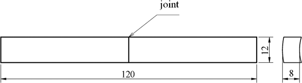
Shape and dimensions of tensile sample
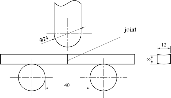
Shape and dimensions of bending sample
Results and discussion
Joint microstructure
The appearance of the joint made using the two-step heating process is shown in Fig. 4. A large plastic deformation as well as a shift of the axes of aluminium alloy pipes is observed in the joint. The deformation is continuous from joint to base metal, and the maximum deformation in the joint is ∼15%.
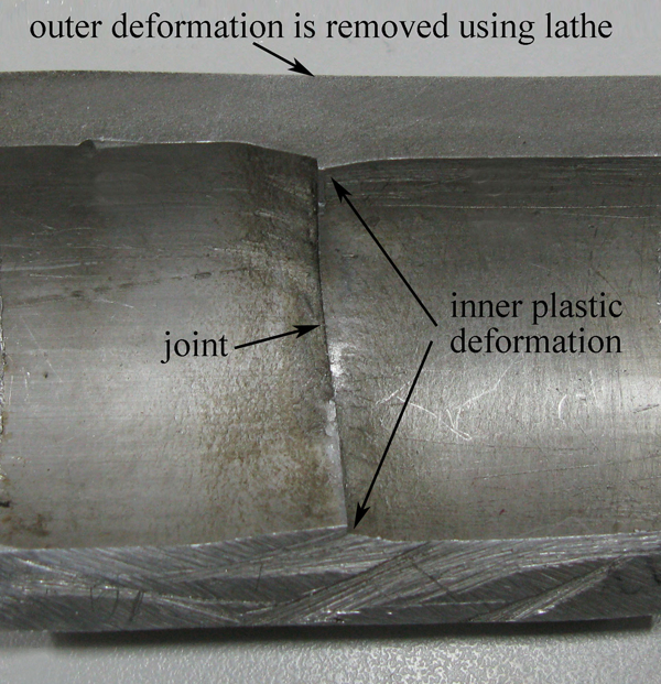
Appearance of joint made using two-step heating process under 7 MPa
Figure 5 shows the cross-sections of TLP bonds made using conventional and two-step heating processes. A planar interface is observed in the conventional TLP bond (Fig. 5a), and a non-planar interface (wave bond line) is observed in the joint by two-step heating process (Fig. 5b). A combination of various Si oxides, other oxides, intermetallics and inclusions are found in the conventional TLP bond. Few defects are found in the joint by two-step heating process, and some metal to metal contacts are established along the wave bond line. This indicates that the defects in the joint can be decreased noticeably by the two-step heating process.
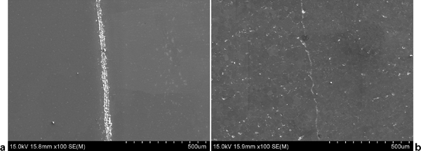
Cross-sections of 5A02 aluminium alloy TLP bonds
Figure 6a illustrates the microstructure of the joint made by the two-step heating process. It can be seen that the main defects in the joint are discontinuous voids. Both Al poor and Si rich occur on the void zone, as shown in Fig. 6b and c. Nevertheless, a uniform distribution of Al and Si is spread across the rest of the joint except for the voids. No compositional variation of Mg is found in the joint, as shown in Fig. 6d. This indicates that the two-step heating process leads to a homogenous joint with a few Si and Al compositional variations. Turriff et al. 13 found that oxides or other impurities on the faying surface could not hinder Si transport in the presence of the transient liquid. Si rich phases would segregate at Al grain boundaries after isothermal solidification. In this paper, however, Si segregates in the voids of the joint. This may be due to the short bonding time that Si cannot diffuse enough from the interlayer to the base metal.
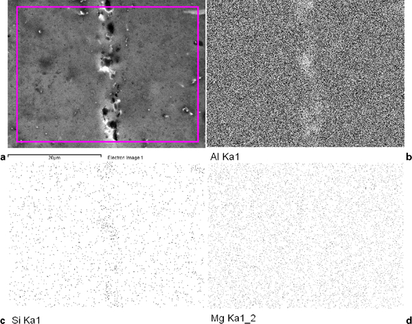
Microstructure and EDX of TLP bond produced by 600°C×5 s–595°C×3 min
Joint properties
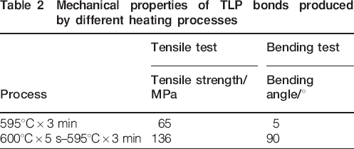
The mechanical properties of TLP bonds are shown in Table 2. Joints made using conventional TLP bonding give a tensile strength of 65 MPa, which is 38% of the base metal strength (170 MPa). The fractograph displays a flat fracture surface, as shown in Fig. 7a. Joints made using the two-step heating process give a tensile strength of 136 MPa, which is 80% of the base metal strength. The fractograph shows a dimple feature of ductile failure, as shown in Fig. 7b. Bending test results show that the ductility of the joint can be dramatically increased using the two-step heating process. The uniform distribution of precipitates is found to be the important factor responsible for the higher tensile strength of aluminium alloy joint.14, 15 In this paper, the superior tensile strength and ductility of the joint may be due to a few defects and the high metal to metal contact along the wave bond line.
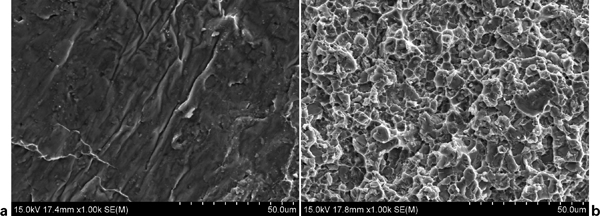
Fractographs of tensile samples made using TLP bonding
Mechanical properties of TLP bonds produced by different heating processes
An SF6 potential transformer conductor tube was TLP bonded using two-step heating process 600°C×5 s–595°C×3 min, as shown in Fig. 8. No failure occurs when the seal test is carried out at 0·6 MPa for 10 min with SF6, and it is successfully applied in transformer substation.
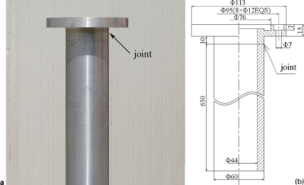
Transient liquid phase bonded conductor tube in SF6 potential transformer
Microstructure evolution in TLP bonding of aluminium alloy using two-step heating process
During the TLP bonding using the two-step heating process, the falling of bonding temperature results in constitutional undercooling at the solid/liquid interface. The equilibrium under isothermal heating is broken, and the solid/liquid interface becomes morphologically unstable, leading to a non-planar interface.10, 12 For the steels, a homogenous joint free of bond line can be produced as their oxide film either dissolves in the bulk of the metal or decomposes at the bonding temperature.1, 10 For the aluminium, the oxide film is chemically stable and will agglomerate in front of the moving solid/liquid interface and affect the bonding strength.1, 3 Referring to the conventional TLP bonding process,1, 2, 16 the evolution of interface and oxide film during TLP bonding using two-step heating is illustrated in Fig. 8. When the interlayer is heated to above its melting temperature T i, the interlayer melts and undermines the surface oxide film (Fig. 9a). The interdiffusion between liquid and base metal leads to partial dissolution of the base metal as the bonding temperature increases from T i to the first holding temperature T 1. The oxide film is then peeled out from the surface and ruptured by the spread of the liquid (Fig. 9b). When the bonding temperature falls from T 1 to the second holding temperature T 2, the solid/liquid interface becomes non-planar due to the break of equilibrium at T 1 (Fig. 9c). During isothermal solidification at T 2, the oxide is convoluted from strip to sphere and redistributed in front of the moving non-planar solid/liquid interface (Fig. 9d). After isothermal solidification, a TLP bond is produced with a few oxide grains (Fig. 9e).
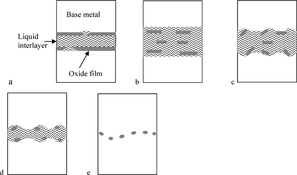
Schematic illusion of microstructural evolution in TLP bonding of aluminium alloy using two-step heating process
In the TLP bonding of aluminium and its alloy, the interlayer is normally copper. As the melting point of copper is higher than that of aluminium, the formation of liquid arises from the solid state interdiffusion between copper and aluminium substrate through the oxide film. Therefore, the bonding time required to form a liquid eutectic phase becomes long due to the low diffusion rate of solid state diffusion. Meanwhile, the composition difference between the copper interlayer and the aluminium substrate also results in a long time to solid state homogenisation. Al–Si and Al–Si–Cu filler metals have been adopted to braze aluminium alloy, but the joints have low shear strength due to the dissimilar joint microstructure.17 Gallium forms a eutectic liquid phase with aluminium at 29°C and has a high solubility in aluminium. It can also disrupt the oxide film and has been used for flux free brazing of pure aluminium3 and TLP bonding of aluminium alloy.18 Referring to this work, a novel Al–Si–Cu–Ga–Ce interlayer alloy is applied for the TLP bonding of aluminium and its alloy. Compared with the present copper interlayer, the Al–Si–Cu–Ga–Ce interlayer has a lower melting point than the bonding temperature and the same main element as the aluminium substrate. It can also disrupt and reduce the oxide film and then produce a strong and ductile joint.
Conclusions
The two-step heating process can produce a wave bond line, which is different from the planar interface associated with conventional TLP bonding at a constant temperature. The defects at bond line are greatly reduced and metal to metal contacts are established along the wave bond line using the two-step heating process. The tensile strength and bending ductility of the joint are dramatically improved.
The 5A02 aluminium alloy conductor tube can be successfully joined by the two-step heating process of 600°C×5 s–595°C×3 min. No failure occurs when the joint is bent to 90°and seal tested at 0·6 MPa for 10 min with SF6, and the conductor tube has been applied in SF6 potential transformer.