
Abstract
The microstructure evolution, hardness and impact toughness in the simulated coarse-grained heat-affected zone (CGHAZ) of a V-N microalloyed X80 pipeline steel were studied. The results indicated that the microstructure mainly consisted of bainitic ferrite, acicular ferrite and granular bainite. The area fraction and size of M/A constituents were increased with increasing heat input. As heat input increased from 15 to 60 kJ cm−1, the hardness gradually decreased from 301 to 243 HV, and impact energy decreased from 284 to 33 J. Hardness in the CGHAZ was not sensitive to heat input. When the heat input exceeded 30 kJ cm−1, the formation of coarse granular bainite and large-sized blocky M/A constituents resulted in the deterioration of impact toughness.
Keywords
Introduction
Pipeline transportation is the most economical and efficient way to transport crude oil and natural gas [1]. At present, high-strength pipeline steels are usually Nb-microalloyed steels, together with Ti and V separately or in combination. The addition of Nb is aimed to retard recovery and recrystallization of deformed austenite during controlled rolling, and Ti is added to form high-temperature stable TiN precipitates which effectively prevent extensive growth of austenite grains during reheating prior to the hot working process and welding process [2,3]. Moreover, precipitate strengthening is also realised because of nano-scale precipitates of Nb and Ti formed during and/or after the transformation from austenite to ferrite, together with the precipitates formed in the austenite region (deformation-induced precipitation) [2-4]. Although a satisfactory combination of strength and toughness is obtained, the flatness control of Nb-microalloyed pipeline steel is difficult because of low final cooling temperature and high cooling rate during thermo-mechanical controlled processing.
Previous studies suggested that coherent and low energy interface is the most important factor for intragranular ferrite nucleation, and VN precipitates can act as effective intragranular nucleation sites because of low lattice mismatch with ferrite [5]. Ishikawa et al. [6] reported that the MnS + VN complex inclusions provide preferential sites for intragranular ferrite nucleation in V-N steel containing high S content, and the intragranular ferrite has a Baker–Nutting orientation relationship with VN. Capdevila et al. [7,8] concluded that the N-rich V(C, N) precipitates without MnS inclusions can also act as ferrite nucleation sites in sulfur-lean vanadium steels, and the strength and toughness were improved with V-N microalloying. The increase of N content in V microalloyed steels can shorten the precipitation incubation period and accordingly promote the formation of V(C, N) precipitates in the austenite region [9]. Therefore, V-N steels usually exhibit small grain size and improved microstructure homogeneity along the direction of steel plate thickness because of the increased rate of intragranular ferrite nucleation. In addition, because of the facilitation of VN precipitates on intragranular ferrite nucleation, acicular ferrite (AF) dominated-microstructure can be obtained in the case of higher final cooling temperature and slower cooling rate in V-N microalloyed steels during thermo-mechanical controlled processing, which contributes to flatness improvement compared with Nb-microalloyed steels. To take advantage of intragranular ferrite nucleation on VN precipitates to obtain small grain size, improved microstructure homogeneity along the thickness direction and flatness improvement, a novel method to fabricate pipeline steels with V-N microalloying was adopted.
Pipeline integrity largely depends on the efficient girth welds, that is, the field welding of pipeline segments [10]. In the previous study, we reported the novel V-N microalloyed pipeline steels mainly consisted of polygonal ferrite (PF) and AF, and the steels exhibited high strength and excellent low-temperature toughness [11]. However, this combination of mechanical properties may deteriorate after a welding thermal cycle because of the occurrence of a local brittle zone (LBZ) in the heat-affected zone (HAZ) [12,13]. As part of the HAZ, coarse-grained heat-affected zone (CGHAZ) is immediately adjacent to the weld fusion line. During welding, the CGHAZ experiences a high peak temperature, resulting in significant austenite grain coarsening, such that on subsequent rapid cooling, high proportion of brittle ferrite side-plates and upper bainite are promoted [14]. Heat input is an important parameter which influences the mechanical properties in the CGHAZ. Xie et al. [15] studied the impact toughness of a high-strength steel that was welded using various heat inputs, and suggested that coarse martensite/austenite (M/A) constituents were the main reason for the dramatic decrease of impact toughness of the simulated CGHAZ specimens with high heat input. A similar result was obtained by Wang et al. [16], they believed that fine and reduced M/A constituents in the CGHAZ were beneficial to impact toughness. However, Zhou et al. [17] thought that M/A constituents cannot directly induce the impact toughness because of the low fraction of M/A constituents in their study. The prior austenite grain size (PAGS) can significantly affect bainite transformation behaviour during austenite decomposition. It is suggested that the decomposition of supercooled austenite is a competitive process between the grain boundary and intragranular transformations [18]. And with increasing PAGS, the transformed microstructure is changed from a boundary-dominated effect to an intragranular-dominated effect, because the number of nucleation sites at prior austenite grain boundaries is decreased. In addition, small PAGS is beneficial for microstructure refinement after continuous cooling, and the microstructural morphology is also changed with different PAGS because of microstructure evolution [19]. Zhu et al. [20] reported that the PAGS increased with increasing heat input and small PAGS was conducive to the improvement of CGHAZ toughness. According to previous studies [16,17,20], the effect of heat input on microstructure and toughness in the CGHAZ of Nb-microalloyed steels has been studied maturely. However, the correlation among heat input, microstructure evolution and toughness in the CGHAZ of V-N microalloyed pipeline steels requires further understanding.
In this study, the welding thermal cycle was explored by a thermal-mechanical simulator. The effect of heat input on microstructure and low-temperature toughness in the simulated CGHAZ was studied. In addition, the morphology of M/A constituents was characterised by TEM and the impact fracture surface together with microcrack propagation path were observed to elucidate fracture micromechanism.
Experimental
Materials and welding thermal cycle
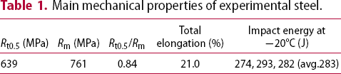
Main mechanical properties of experimental steel.
The welding thermal simulation was conducted using a thermo-mechanical simulator developed by Northeastern University. The simulated specimens of dimensions 11 mm × 11 mm × 55 mm were prepared along the transverse direction. The specimens were heated to 1300°C at a rate of 100°C s−1 and then held for 1 s. After which, the specimens were cooled to 300°C, heat input of 15, 30, 40, and 60 kJ cm−1 were selected. The corresponding t8/5 times (the times taken to cool from 800°C to 500°C) were 20, 82, 146, and 327 s, respectively, calculated using the Rykalin mathematical model [21]. The thermal cycle curves are presented in Figure 1.
Welding thermal cycle curves of the simulated CGHAZ specimens.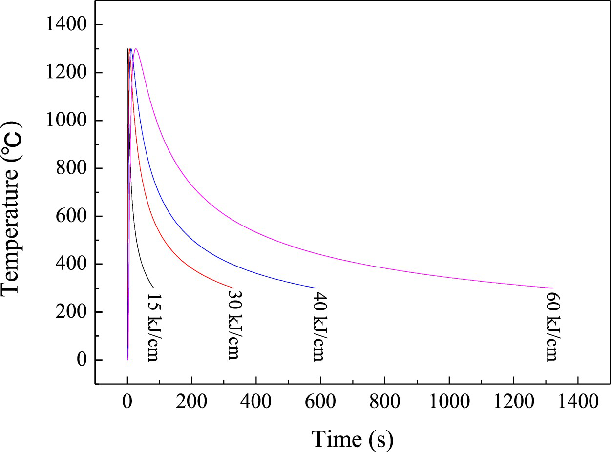
Microstructural characterisation
Metallographic specimens in the CGHAZ were prepared from the vicinity of thermocouple. The specimens were mechanically polished and etched with 4% nital solution and LePera reagent [22], respectively. The microstructure of the experimental steel and CGHAZ specimens was examined by an Olympus optical microscope (OM) and FEI Quanta 600 scanning electron microscope (SEM) equipped with an energy-dispersive X-ray spectroscopy (EDX). The chemical composition of inclusions was determined by EDX analysis. The area fraction of M/A constituents was obtained by Image Pro-Plus 6.0 at 1000× using 10 images for each thermal cycle condition. More detailed microstructural characteristics were observed by an FEI Tecnai G2 F20 transmission electron microscope (TEM). Thin foil samples for TEM were first mechanically ground from 200 to 50 μm thickness and then 3 mm diameter disks were punched, which were finally electropolished using a twin-jet polishing machine at −30°C in an electrolyte of 8% perchloric acid and 92% ethanol.
Mechanical properties
After welding thermal simulation, Charpy V-notch specimens of dimensions 10 mm × 10 mm × 55 mm were prepared according to ASTM E23 specification. Charpy impact tests were conducted using a ZBC2302-B pendulum impact test machine at −20°C, and the impact toughness of each heat input was the average value of three repeated tests. The FEI Quanta 600 SEM was used to observe the fracture surface of impact specimens. The Vickers microhardness was measured by an FM700 hardness tester using a load of 500 g, and the average value of 10 points was obtained at each circumstance.
Results
Microstructure of the simulated CGHAZ specimens
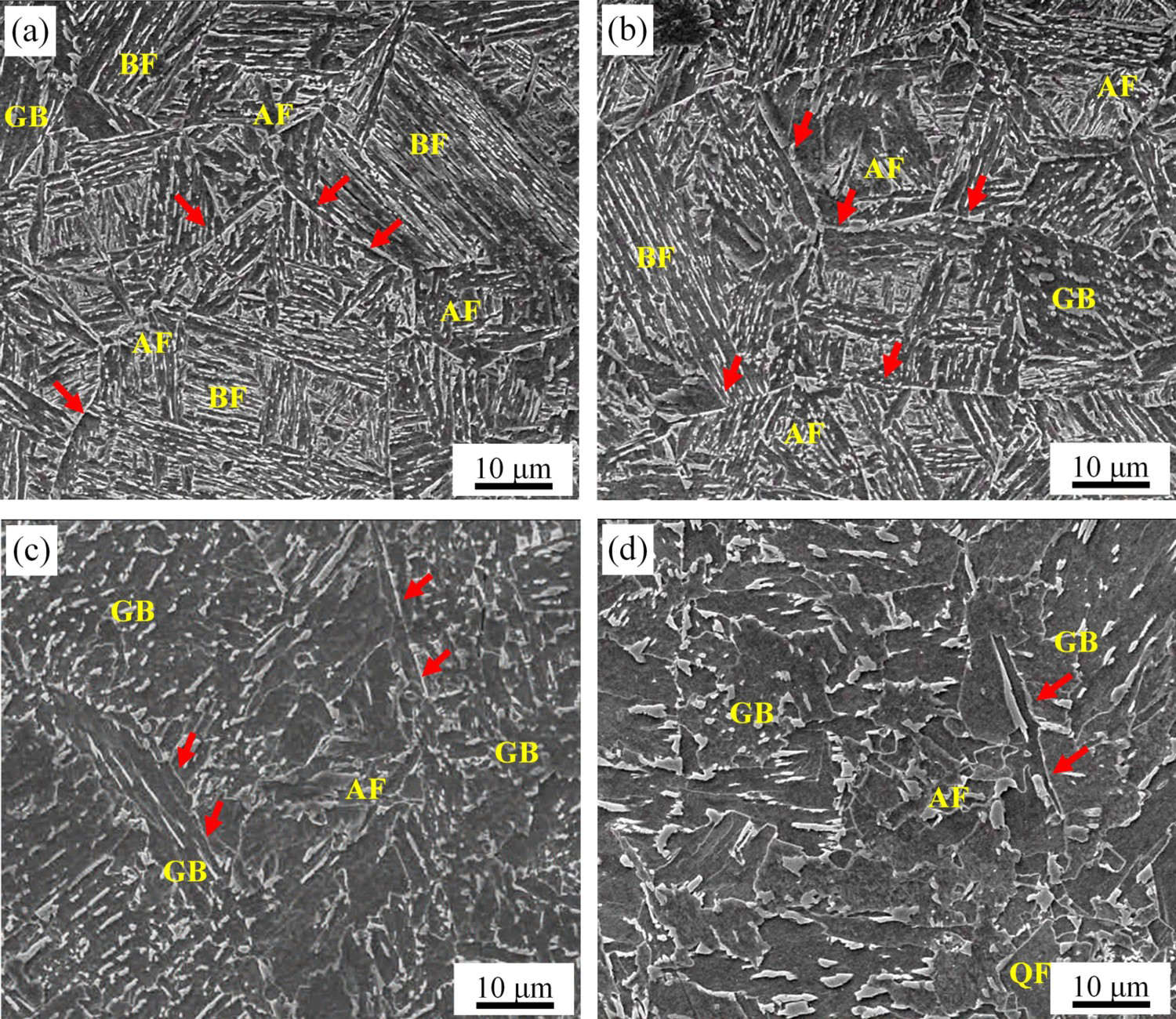
Figure 2 shows the microstructure of the experimental steel. It mainly consisted of AF and PF, and fine M/A constituents dispersed on AF matrix or along ferrite boundaries. Figure 3 shows SEM micrographs of the simulated CGHAZ specimens at different heat inputs with a peak temperature of 1300°C, indicating that the microstructure changed with the increase of heat input. The microstructure of the specimen subjected to heat input of 15 kJ cm−1 mainly consisted of AF together with a small amount of bainitic ferrite (BF) and granular bainite (GB) (Figure 3(a)). As the heat input was increased, the amount of BF was decreased, while the amount of GB was increased. At heat input of 30 kJ cm−1, the microstructure was mainly composed of AF and GB together with a small amount of BF (Figure 3(b)). When the heat input was increased to 40 kJ cm−1, BF was disappeared, and the microstructure consisted of GB and AF (Figure 3(c)). When the heat input was increased to 60 kJ cm−1, the continuous cooling rate was really slow, resulting in the appearance of quasi-polygonal ferrite (QF), and the microstructure was predominantly coarse GB together with a small amount of AF and QF (Figure 3(d)). QF forms at a slow cooling rate and has irregular and jagged grain boundaries. AF is generally characterised by a small grain size, adjacent AF laths sometimes form packets, which have an irregular grain morphology. BF consists of fine parallel laths and some of these lath boundaries are high angle grain boundaries, which are prone to be revealed by etching with nital. Therefore, BF corresponds to the areas with a clear lath-like morphology. GB is composed of wide parallel laths, because low angle grain boundaries between the laths are insensitive to nital, GB packets look like grains with an equiaxed shape [23]. Area fraction of different phases was determined by point-counting method and given in Table 2. It is clear that prior austenite grain boundaries were retained in each specimen (identified by red arrows), implying that the growth of the transformation products is constrained within prior austenite grains involving shear mechanisms [24].
Microstructure of experimental steel: (a) OM; (b) SEM. SEM micrographs of the simulated CGHAZ with different heat inputs: (a) 15 kJ cm−1; (b) 30 kJ cm−1; (c) 40 kJ cm−1; (d) 60 kJ cm−1. Area fraction of different phases in the CGHAZ specimens.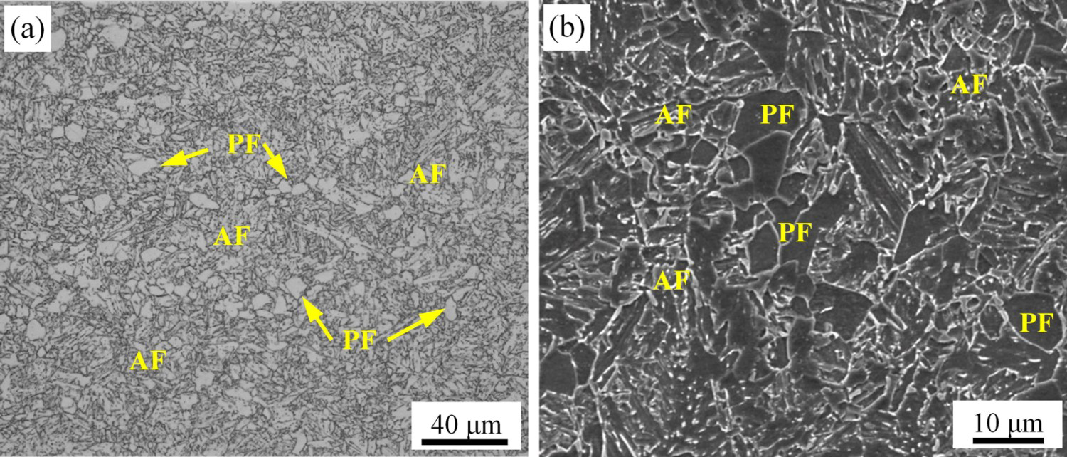
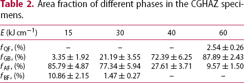
The inclusions with different morphological features and sizes in the CGHAZ at the input heat of 30 kJ cm−1 are shown in Figure 4. It can be seen that these inclusions were at a micrometer scale and the large-sized inclusions were not well coherent to the steel matrix. The chemical composition (atomic percentage) of each inclusion, as shown in Table 3, suggested that the inclusions were Al-rich oxides and contained Mg, S, Mn, Ca, Cu and Si. In addition, ferrite grains were found to nucleate on the non-metallic inclusions intragranularly, which was beneficial for microstructure refinement.
SEM micrographs of inclusions in the CGHAZ at the input heat of 30 kJ cm−1. Chemical composition (atomic percentage) of the inclusions in Figure 4.
Distribution of M/A constituents in the simulated CGHAZ specimens
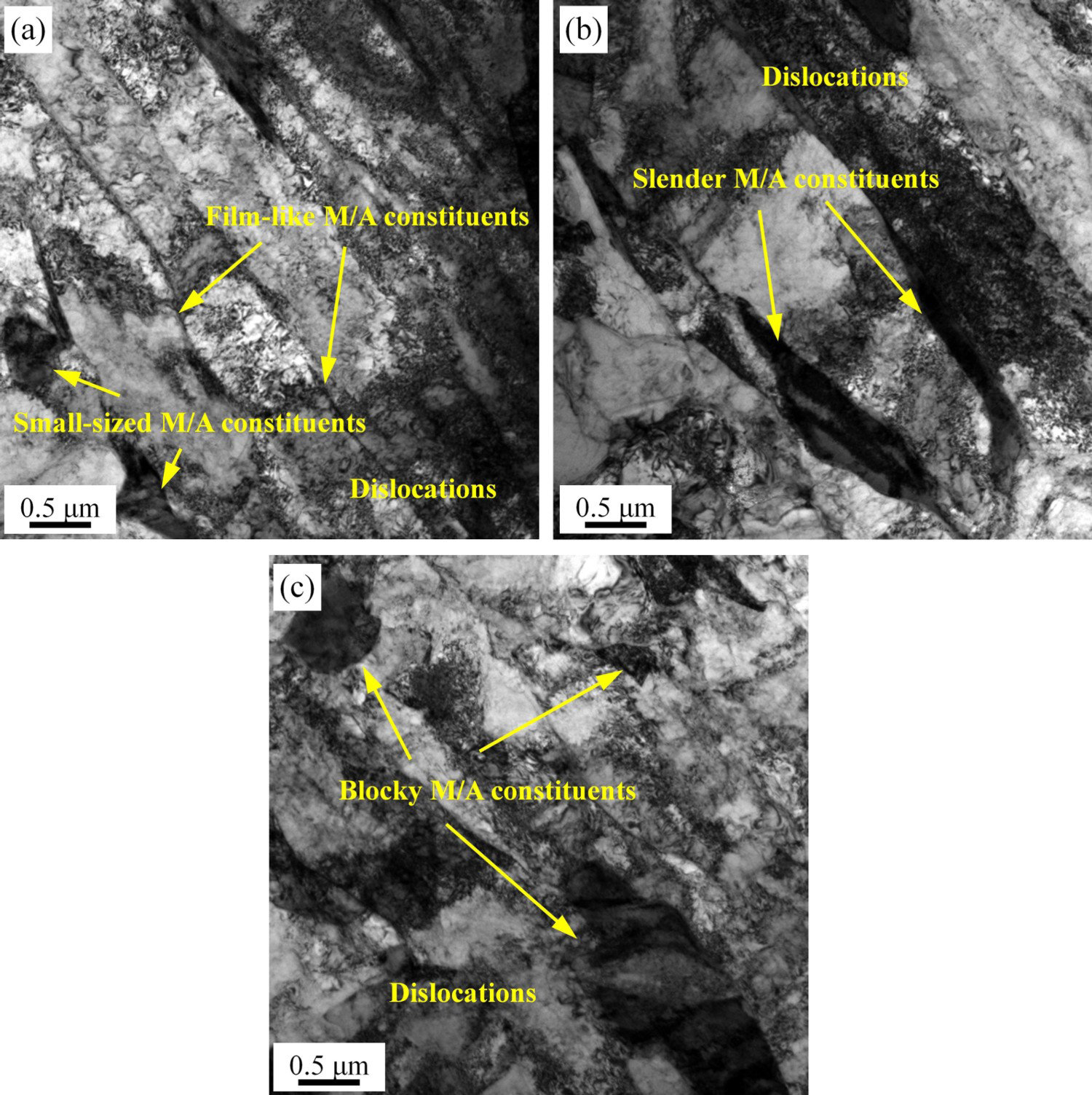
As an important second phase in low carbon bainitic steels, M/A constituents are composed of martensite and retained austenite and formed during continuous cooling [25]. The distribution and morphology of M/A constituents with different heat inputs are shown in Figure 5, in which, ferrite matrix (gray phase) and M/A constituents (white phase) can be identified. It can be seen from Figure 5 that M/A constituents were located both at the prior austenite grain boundaries and between ferrite laths, and as the heat input increased, the number of irregular and slender M/A constituents increased. The typical M/A constituents of different morphologies were revealed by TEM, as shown in Figure 6. The film-like and slender M/A constituents depicted the position of lath boundaries, and some small-sized M/A constituents were entrapped among ferrite laths (Figure 6(a,b)). Meanwhile, large-sized blocky M/A constituents were also present frequently in the ferrite matrix (Figure 6(c)). Relatively high density of dislocations was present in ferrite laths because of the shear transformation mechanism. In addition, martensitic transformation and volume expansion led to high dislocation density in the vicinity of blocky M/A constituents.
Distribution and morphology of M/A constituents in the simulated CGHAZ: (a) 15 kJ cm−1; (b) 30 kJ cm−1; (c) 40 kJ cm−1; (d) 60 kJ cm−1. TEM micrographs of (a) film-like M/A constituents at 15 kJ cm−1; (b) slender M/A constituents at 30 kJ cm−1; (c) blocky M/A constituents at 60 kJ cm−1.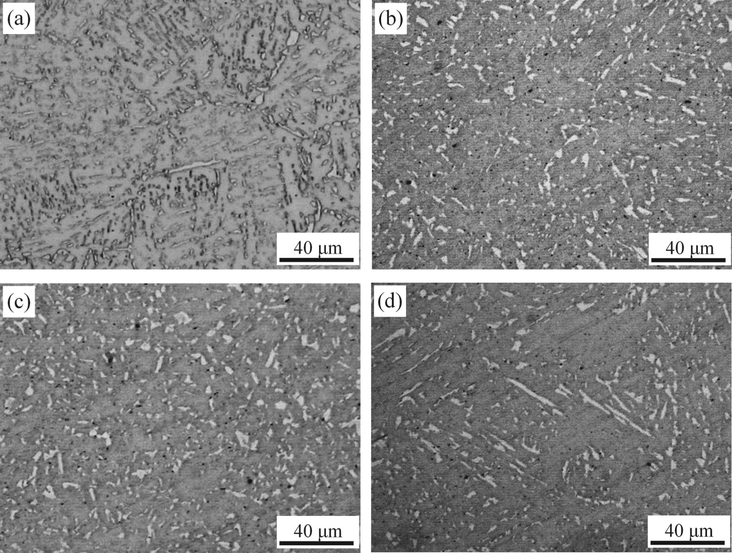
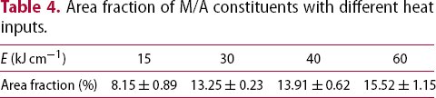
According to the statistical results using Image Pro-Plus, the area fraction of M/A constituents with different heat inputs are listed in Table 4. The area fraction increased from 8.15% to 15.52% when the heat input was increased from 15 to 60 kJ cm−1. Figure 7 is the particle size (in length) distribution of M/A constituents when the heat input was 30 and 60 kJ cm−1. It can be seen that when the heat input was 30 kJ cm−1, M/A constituents were mainly in the range of 0–2 μm. When the heat input was increased to 60 kJ cm−1, the size of M/A constituents was increased, the size was mainly in the range of 0–3 μm, and the number of M/A constituents was highest in the range of 1–2 μm. In addition, the number fraction of M/A constituents less than 1 μm were 48.6% and 29.8%, when the heat input was 30 and 60 kJ cm−1, respectively.
Particle size distribution of M/A constituents for the heat input of 30 and 60 kJ cm−1. Area fraction of M/A constituents with different heat inputs.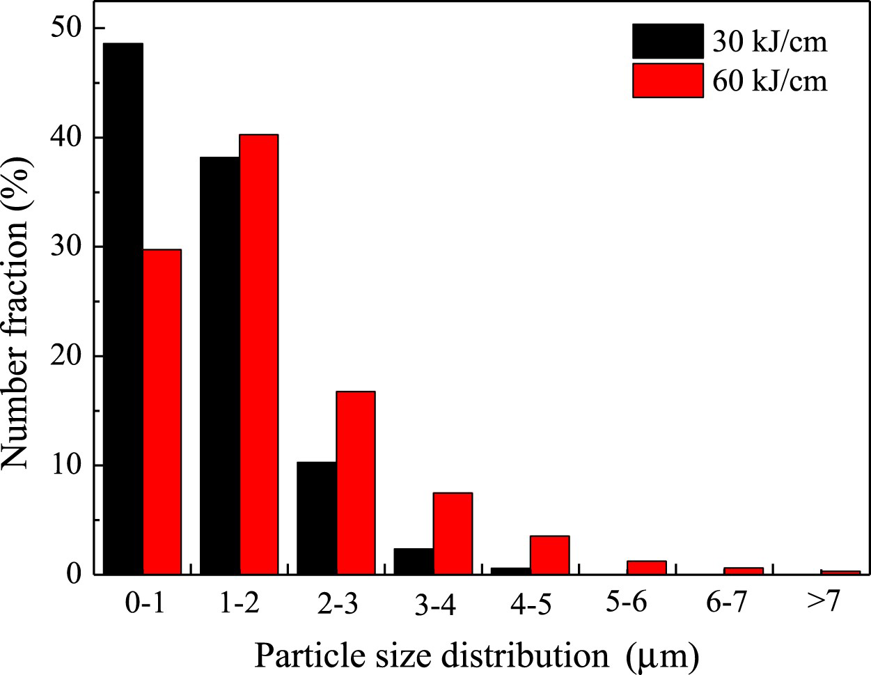
Hardness and impact toughness of simulated CGHAZ specimens
The Vickers hardness values of the simulated CGHAZ specimens as a function of heat input are shown in Figure 8. It can be seen that the hardness was gradually decreased with the increase of heat input. When the heat input was increased from 15 to 60 kJ cm−1, the hardness decreased from 301 to 243 HV. HAZ hardness is an indicator of cold cracking susceptibility during welding, and the risk of cold cracking is significantly low when the hardness value is less than 350 HV [13,17]. As regards the hardness values mentioned above, the present X80 pipeline steel has good weldability.
Hardness of the simulated CGHAZ specimens as a function of heat input.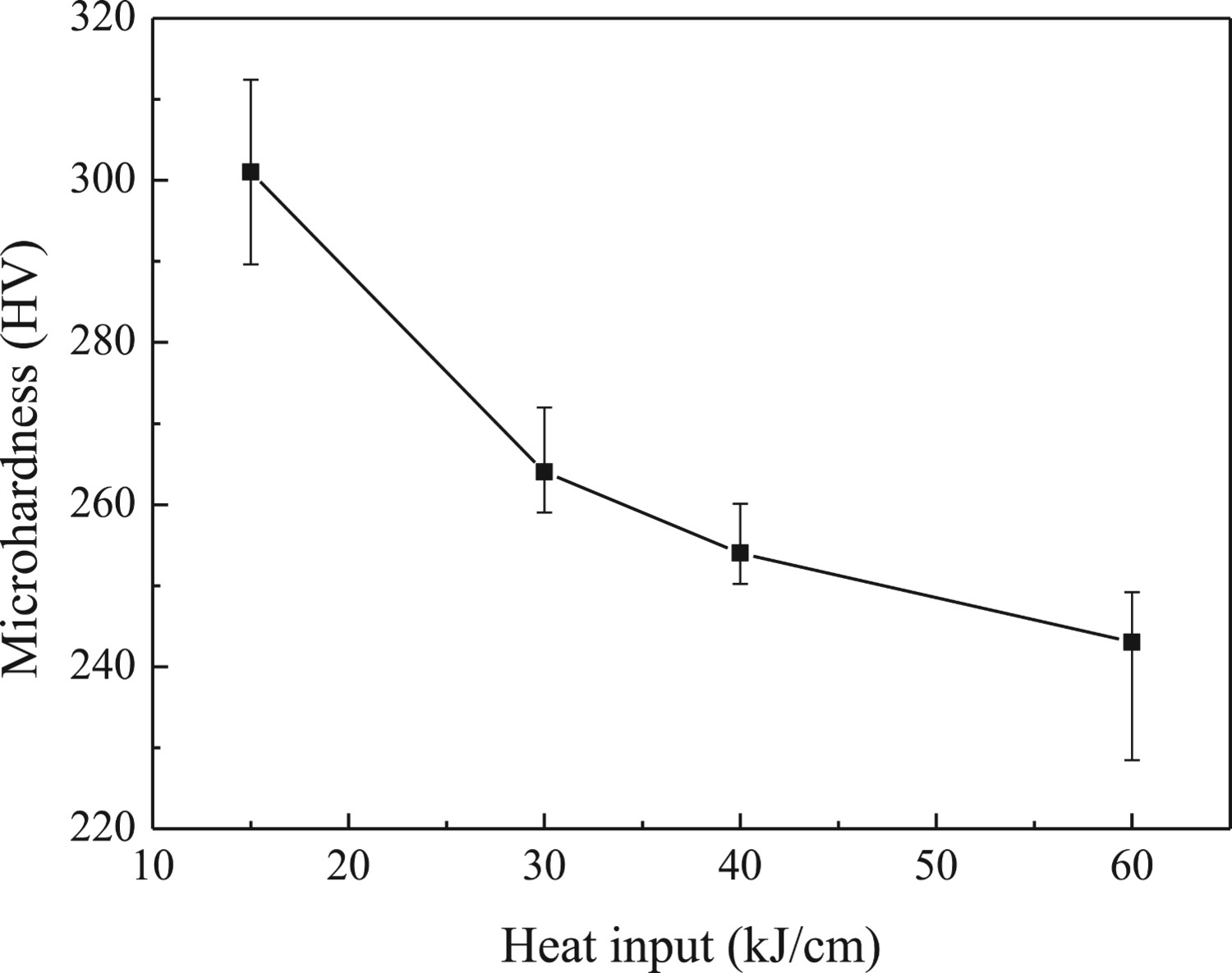
Compared with the hardness, the impact energy was more sensitive to heat input, as shown in Figure 9. When the heat input was increased from 15 to 30 kJ cm−1, the impact energy was decreased from 284 to 233 J. According to the Chinese standard GB/T 21237-2018, the required impact energy of X80 pipeline steel at −20°C is 150 J. Therefore, the simulated CGHAZ specimens at a heat input of 15 and 30 kJ cm−1 exhibited excellent impact toughness. Moreover, the impact energy decreased rapidly when the heat input exceeded 30 kJ cm−1. When the heat input was increased to 60 kJ cm−1, the impact energy was only 33 J, which was only ∼11.7% of the base metal (283 J), implying embrittlement.
Impact energy of the simulated CGHAZ specimens as a function of heat input.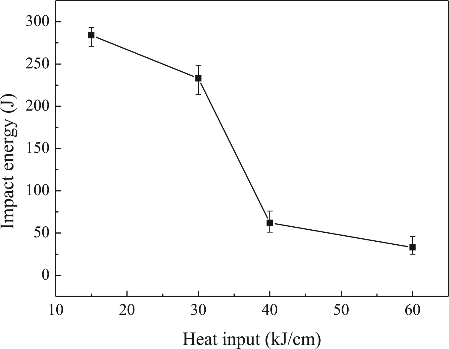
The fracture morphology corresponding to radial regions of the impact specimens with different heat inputs is presented in Figure 10. It was observed that the cleavage facets were relatively small and the river patterns were feeble at a heat input of 15 and 30 kJ cm−1 (Figure 10(a,b)). There were ductile tear ridges with small dimples in cleavage fracture regions, which largely increased the impact energy because of the occurrence of energy dissipating micromechanisms during crack propagation [26]. As the heat input was increased to 40 and 60 kJ cm−1, the fracture cleavage facets were relatively enlarged, and the straight river patterns extended from the nucleation sites of cleavage cracks to the periphery (Figure 10(c,d)), indicative of a typical brittle fracture. In addition, inclusions were found on the fracture surface, as shown in Figure 10. Composite small-sized oxide inclusions can promote nucleation of intragranular ferrite and improve the impact toughness, but large-sized inclusions can act as a source of microcracks, resulting in the decrease of toughness. Tweed et al. [27] suggested that the critical size of inclusions which were detrimental to toughness was ∼1 μm in diameter.
Fracture morphology corresponding to radial regions with different heat inputs: (a) 15 kJ cm−1; (b) 30 kJ cm−1; (c) 40 kJ cm−1; (d) 60 kJ cm−1.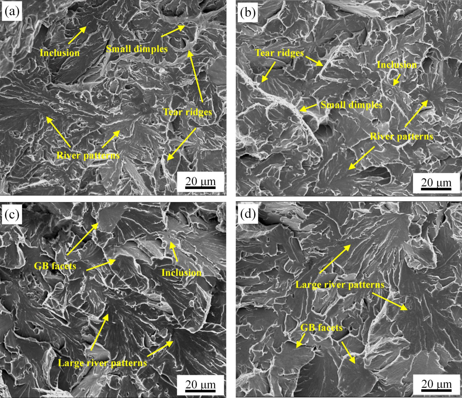
To study the crack propagation, secondary cracks just beneath the fracture surface and primary crack on the fracture surface of the impact specimen at a heat input of 60 kJ cm−1 were observed. It can be seen in Figure 11(a), secondary cracks nucleated around large-sized M/A constituents and propagated in a straight line in the interior of GB without deflection until prior austenite grain boundaries or GB packet boundaries were encountered (identified by white arrows). In addition, secondary cracks can also be arrested at the boundaries (identified by red arrows). Unit crack path in brittle fracture propagation represents the crack length of almost straight-line propagation and is generally considered to be the distance between two neighbouring high angle grain boundaries [28]. Previous studies reported that smaller effective grain size and shorter unit crack path mean better low-temperature toughness, and the length of unit crack path increases in the order of AF, PF and GB [28-30]. At heat input of 60 kJ cm−1, the unit crack path was relatively long and straight, as shown in Figure 11(b), and the cleavage crack path deflected at high angle grain boundaries. The average length of unit crack path was measured to be ∼9.5 μm.
(a) Secondary cracks and (b) primary crack propagation path beneath the fracture surface.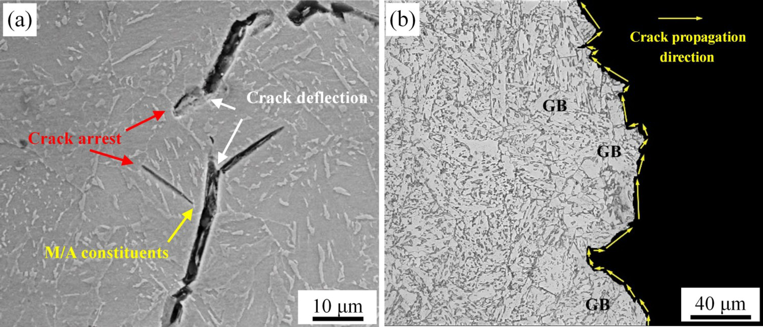
Discussion
Effect of heat input on microstructure evolution of the CGHAZ specimens
The microstructural characteristics of the CGHAZ depend on the welding thermal cycle process to a great extent. In the present study, during the reheating stage, the microstructure transformed from PF and AF to austenite, and coarse austenite grains formed at the high peak temperature (1300°C). During continuous cooling, ferrite nucleated when the temperature was in the ferrite transformation regime. It is well known that the nature and characteristics of transformation products are largely determined by the PAGS and cooling rate [19,22,31]. In the process of welding thermal cycle, heat input is a critical parameter, which has an important role on the PAGS before ferrite transformation and cooling rate. Low heat input means a large cooling rate, when the austenite grain boundaries do not have adequate time to migrate, as a result, further coarsening of the austenite grains is hindered [32]. It is suggested that parallel BF laths nucleate at prior austenite grain boundaries, while AF laths nucleate on dislocations, substructures and non-metallic inclusions in prior austenite grains, and the laths have any orientation relationship with respect to austenite [31,33]. Therefore, small austenite grain size increases the austenite grain boundary density per unit volume, leading to an increased nucleation rate of BF laths, which is beneficial for the formation of BF. Furthermore, the microstructure evolution exhibits different features at different cooling rates because of the change of carbon diffusion rate [33]. Large cooling rate increases the undercooling during phase transformation and further promotes BF transformation. Many studies concluded that not only AF laths can nucleate on crystal defects and non-metallic inclusions, but VN and N-rich V(C, N) precipitates can also act as effective nucleation sites to facilitate the formation of AF. According to Equation (2) [34], the solubility product of VN in austenite, the start precipitation temperature of VN in the experimental steel was calculated to be 1131°C. During cooling, when the temperature decreased below 1131°C, VN started to precipitate, which facilitated the formation of AF. Therefore, at heat input of 15 kJ cm−1, the microstructure mainly consisted of AF together with BF (Figure 3(a)). With increasing the heat input from 15 to 30 kJ cm−1, the increased PAGS and reduced cooling rate resulted in the decreased fraction of BF. In addition, the reduced cooling rate increased the ferrite transformation temperature and the carbon diffusion coefficient in austenite, and thus the amount of GB increased. The microstructure was mainly composed of AF and GB (Figure 3(b)).
The precipitation behaviour in the CGHAZ largely depends on heat input, because the different heat inputs result in the changed kinetic condition [35]. It is suggested that the number of critical nucleus is decided by undercooling and the atom attaching frequency is determined by local diffusivity [21]. Thus, a maximum nucleation frequency can be achieved at the intermediate undercooling. Moreover, the size of precipitates is large at low undercooling because of the large atomic diffusion rate. Research shows that the facilitation of intragranular ferrite nucleation on particles is enhanced when the particle size is enlarged [36]. Further increasing heat input to 40 and 60 kJ cm−1, though the prior austenite grains grew abnormally and the size of VN precipitates was large, the microstructure was mainly consisted of coarse GB (Figure 3(c,d)). This can be attributed to the further increased ferrite transformation temperature because of the slow cooling rate. Therefore, the assistance of suitable undercooling and the presence of intragranular nucleation sites were both the important factors for the formation of AF.
With the progress in ferrite transformation, carbon atoms continuously diffused from ferrite to the adjacent austenite. The rise of average carbon content in untransformed austenite resulted in the increase of austenite stability, which retarded the transformation to BF, AF and GB during the subsequent cooling procedure. When the temperature decreased below the martensite transformation temperature, part of the untransformed austenite transformed to martensite, and thus M/A constituents formed finally as second phase [37]. As the heat input was increased, the cooling rate was decreased, carbon atoms had enough time to diffuse, which resulted in an increase of area fraction and size of M/A constituents (Figures 5 and 7). The area fraction and size of M/A constituents can be positively correlated with prior austenite grain size. In addition, the morphology of M/A constituents also varied with the heat input. As the heat input was increased, the microstructure gradually changed from BF to AF and GB, and the width of ferrite lath was increased, as shown in Figure 6. The variation of lath structures had a combined effect on the morphology of M/A constituents between the laths. When the heat input was small, the cooling rate was high and the diffusion of atoms was difficult, small-sized and film-like M/A constituents were formed between the ferrite laths (Figure 6(a)). As the heat input was increased to 30 kJ cm−1, the cooling rate was slow, and the increased hold time at high temperature rendered the lath size to become wider, such that the M/A constituents were present between them (Figure 6(b)). Further increasing the heat input, carbon atoms had enough time for long-range diffusion. The peak concentration of carbon accumulated in the front of the phase interfaces by uphill diffusion decreased and the carbon-rich region expanded because of long-range diffusion [38]. With the decrease of temperature, these remaining carbon-rich austenite regions transformed into large-sized blocky M/A constituents (Figure 6(c)).
Effect of microstructure on mechanical properties of the CGHAZ specimens
The V(C, N) precipitates, dislocations and effective grain size are the important factors for hardness variation [21]. According to the previous studies [21,35], with the increase of heat input, the size of V(C, N) precipitates was increased, which had unfavourable effects on precipitation hardening. Furthermore, with the increase of heat input, the time for carbon diffusion increased, reducing the density of lattice defects, and thus dislocation strengthening was reduced. Generally, hardness is mainly related to the microstructure type such as pearlite, ferrite, bainite and martensite [16]. In this study, the CGHAZ microstructure of all the specimens subjected to different heat inputs mainly consisted of bainite-type microstructure (including BF, AF and GB). With increasing heat input, the increased fraction of coarse GB resulted in a large effective grain size. Consequently, the hardening effect originating from grain boundary was reduced, leading to further reduction of the hardness. Therefore, the hardness was gradually decreased with the increase of heat input, though the area fraction of M/A constituents was increased, as shown in Figure 8. When the heat input was 15 kJ cm−1, the AF-dominated microstructure contributed to a maximum value of 301 HV, and hardness decreased to 243 HV because of coarse GB, when the heat input was 60 kJ cm−1.
Impact toughness of the CGHAZ specimens largely depends on the microstructure. It is believed that only high misorientation boundaries can be transformed to cleavage facet boundaries, and energy consumption is needed to change the propagation direction of microcracks after being blocked at the cleavage facets [39]. Figure 12 is a schematic illustration of crack propagation paths in AF and GB structures while cleavage fracture is propagated. AF is composed of nonparallel ferrite laths, which are separated by high angle grain boundaries, although sub-units within the laths have nearly identical orientations [30]. The large fraction of high angle grain boundaries in AF-dominated microstructure can frequently deflect the cleavage crack propagation direction during impact deformation (Figure 12(a)), which consumes more energy for crack growth. In addition, interwoven ferrite laths in AF can also retard the cleavage crack propagation and consequently enhance the impact toughness. Therefore, when the heat input was 15 kJ cm−1, the impact energy was highest (284 J) because of the large proportion of AF, as shown in Figure 3(a). Substructure inside the GB packets have similar crystallographic misorientation to one another, and the boundaries between GB laths are usually low angle grain boundaries, which have no effect on crack propagation (Figure 12(b)). The cleavage facet size in GB microstructure equals the packet size, and the large-sized cleavage facets demonstrate very low crack propagation energy [21]. At heat input of 30 kJ cm−1, the microstructure consisted of BF, AF, and GB (Figure 3(b)), and the increased amount of GB resulted in a reduction of impact energy (233 J). Further increasing the heat input to 40 and 60 kJ cm−1, the microstructure mainly consisted of coarse GB (Figure 3(c,d)). Coarse GB implied large effective grain size, and the cleavage crack deflected only when prior austenite grain boundaries and GB packet boundaries were encountered, which resulted in enlarged unit crack paths (Figure 11(b)). Large-sized cleavage facets and enlarged unit crack paths in GB-dominated microstructure deteriorated the impact toughness when the heat input was greater than 30 kJ cm−1, as shown in Figure 9.
Schematic diagram of crack propagation path: (a) AF structure and; (b) GB structure.
Previous studies indicated that the morphology and size of M/A constituents in high-strength bainitic steels play an important role in impact toughness at low temperatures [25,40]. During impact deformation, strain mismatch between M/A constituents and ferrite matrix exists because of the strength difference, resulting in a stress concentration at the interfaces. When the stress is higher than the critical stress, microcracks nucleate at the interfaces between M/A constituents and ferrite matrix, which is harmful to impact toughness. According to the Griffith theory [41]:
Conclusions
The microstructure evolution and mechanical properties of V-N microalloyed X80 pipeline steel after simulated welding thermal cycles with different heat inputs were studied. The main conclusions were summarised as follows:
The microstructure of the CGHAZ specimens changed with heat input. When the heat input was small, the microstructure mainly consisted of AF together with a small amount of BF and GB. With the increase of heat input, the amount of BF was decreased and the amount of GB was increased, the microstructure was composed of AF and GB with a small amount of BF. Further increasing the heat input, the microstructure was dominated by coarse GB. The size and area fraction of M/A constituents were increased with the increase of heat input. The morphology of M/A constituents varied with heat input. When the heat input was small, the M/A constituents were film-like and slender. But with an increase in heat input, M/A constituents were mainly characterised by block because of the long-range diffusion of carbon atoms. The hardness decreased gradually as the heat input was increased. In view of the dominating bainite-type microstructure, hardness of the CGHAZ specimens subjected to different heat inputs fluctuated within a narrow range. The impact toughness was sensitive to heat input, when the heat input was higher than 30 kJ cm−1, the impact energy decreased rapidly because of the formation of coarse GB and large-sized M/A constituents.
Footnotes
Acknowledgements
The authors at NEU are extremely grateful to R. D. K. Misra for his willingness to collaborate and meaningful discussion.
Disclosure statement
No potential conflict of interest was reported by the author(s).
Correction Statement
This article has been republished with minor changes. These changes do not impact the academic content of the article.