
Abstract
Two different alloys were developed from the mixtures of pre-alloyed powders consisting of ferroalloys to get the required composition of austenitic stainless steel via the powder metallurgy technique along with the presence and absence of Y2O3. The subsequent mechanical alloyed powders were subject to vacuum hot pressing at 1200°C. The samples were subject to microstructural characterisation post-vacuum hot pressing process. With the addition of yttria, the structure of the grains was fine for the mechanical alloyed vacuum hot pressed samples. The TEM analysis revealed the presence of heterogeneous distribution of yttria particles along the grain boundaries. With the addition of yttria within the metal matrix, the hot pressed density was increased marginally.
Introduction
Introduction to austenitic stainless steel
For high-temperature applications such as automobile, aerospace and nuclear reactors, heat resistance alloys with the presence of chromium and nickel in the metal matrix result in excellent oxidation resistance and good creep strength. One such material which was widely used since 1950 is 21-4N alloy that contains 21 wt-% of chromium, 4 wt-% of nickel along with manganese, carbon, silicon and iron [1]. In conventional alloys, creep resistance is reduced to above 500°C due to recrystallization, grain coarsening and precipitate dissolution. Alloys consisting of ferritic and martensitic structures are preferably utilised within nuclear power plants due to their excellent void swelling resistance, but the presence of a body-centred crystal (BCC) structure leads to poor creep resistance. Alloys consisting of face-centred cubic (FCC) structure have a closed packing with better creep resistance. High-temperature properties such as ductility, ultimate tensile strength, yield strength and hardness are inferior when compared with its corresponding room temperature mechanical properties. Mechanical properties of the materials have to be improved to extend the service life as well as performance enhancement. At elevated temperatures, alloys with the FCC structure are having a stable phase which is an inherent property.
Oxide dispersion strengthening
Strengthening mechanisms like solid solution strengthening and precipitate hardening mechanisms were done to alloys containing the FCC structure to enhance its creep strength with the addition of V, Zr, Nb and Ti [2-5]. The enhancement of high-temperature properties with respect to mechanical strength is obtained with the addition of dispersion strengthened materials which improve the strength through the dispersion mechanism [6-8]. The existence of fine oxide dispersion strengthened (ODS) particles enhance the high-temperature properties of the materials by retarding grain boundary sliding, recrystallization and grain coarsening. Materials that are developed with precipitate strengthened materials namely nitrides and carbides are less stable when compared with ODS strengthened materials at elevated temperatures. The distribution of dispersoids is usually heterogeneous within the metal matrix when ODS alloys are produced through casting processes [9]. Several researchers have investigated the presence of ODS in iron–chromium–nickel alloys which are the promising material for high-temperature applications [10-16]. The presence of dispersoids like ODS prevents the movement of dislocations at high temperatures which improve the high-temperature properties and creep resistance [17]. Grain boundary sliding and recrystallization are restricted with the presence of ultrafine ODS particles which increase high-temperature strength of the materials [18,19]. Mechanical properties are enhanced with the presence of ODS within the metal matrix which controls grain growth and resists dislocations [20]. Dislocations accumulated near the nanoparticles results in stacking up of dislocations during strain hardening thereby resisting plastic deformation.
Mechanical alloying
One of the methods to process powder particles is through a mechanical alloying (MA) technique, where these oxide particles are distributed homogeneously throughout the alloy. Initially, Benjamin et al. carried out the MA technique to mix ODS with super alloy for high-temperature applications [21,22]. The metal matrix is uniformly distributed with insoluble ODS particles by the process of MA which is a solid-state processing technique. Heavy deformations are imparted to the particulates during the process of MA along with a high amount of energy [23]. Similarly, crystals defects namely dislocations and grain boundaries are created within the material. Solute elements are diffused into the metal matrix and further enhanced due to defective structures which lead to solid solution formation and atomic-level alloying [24]. Phaniraj et al. developed the composition of austenitic stainless steel through MA by altering the percentage of Y2O3 which activated the formation of alloying due to the presence of Y2O3 [25]. The consolidation of the milled powders is done by using vacuum hot pressing where these ODS particles re-precipitate and improve high-temperature properties [26,27]. However, not much effort had been made to study the effect of Y2O3 during alloys formation from pre-alloyed mixtures containing ferroalloys through the powder metallurgy route.
In the current study, the alloy consisting of 21 wt-% Cr, 4 wt-% Ni and 9 wt-% Mn were developed from pre-alloyed mixtures of ferroalloys by varying the Y2O3 content to attain a chemical composition of 4Ni–21–Cr–9Mn–0.4Si–0.5C–restFe through the MA process. The evolution of alloy through this process with the absence of yttria is termed as sample A, whereas yttria addition of 0.3 wt-% is termed as sample B. The MA powders were subsequently consolidated using vacuum hot pressing and here densification studies were demonstrated in the present work. Moreover, the effects of yttria addition in the alloy were studied through various characterisations techniques like optical micrographs, XRD, SED-EDS and TEM.
Materials and methods
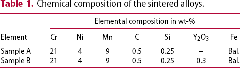
Chemical composition of the sintered alloys.
Results and discussion
Morphology of powders
Variation in powder morphology during MA for various milling times is shown in Figure 1(a–e,f–j) for samples A and B, respectively, which was analyzed by using the SEM. Figure 1(a,f) shows the morphology of powder for samples A and B done under unmilled/as-received condition, similarly, Figure 1(b–e) shows the powder morphology of sample A for 5–20 h of milling and Figure 1(g–j) for sample B. The average size of the powder particles was of ∼180 µm at the beginning of milling with flakey and elongated structures. Observation from the as-milled powders through SEM morphology revealed very minimal plastic deformation and no evidence of agglomeration at the initial stages. As a result of intensive milling, considerable changes were observed. Particle fragmentation took place due to milling for a period of 20 h which led to the decrease in powder size. When compared to the as-milled powders the characteristics of powder morphology reveal that after 10 h of milling, fracturing of powder occurred as a result of deformation between ball-powder-wall collision as shown from Figure 1(c–h). Further as milling time increases, the dominance due to cold welding led to the surface area reduction of the powder particles due to which agglomeration is clearly visible from Figure 1(e,j). Agglomeration of powder particles can be accounted to ductile nature of the alloys which makes the mechanically milled powders to get clustered as a result of cold welding which is similar to work carried out by Haghir et al. where the amount of chromium and manganese content is 18 and 11 wt-%, respectively [28]. When closely looking at the agglomerated particles after 20 h of milling, it can be seen that agglomeration is due to the accumulation of smaller particles in a large number. Powder particles were broken down into smaller pieces, when repeated collision led to friction between the mixed powders along with compression and shear which contributed to the work hardening and strain accumulation. Moreover, fractured and flattened powder particles tend to form large agglomerated particles. Lamellar or layered structures were present within the pre-alloyed powders at the beginning stages of alloying. These lamellar-structured powders are further refined and the thickness of these layered structures is continuously fragmented as a result of repeated fractures due to frequent collision among balls and powder mixtures during sporadic stages of MA. Particle size and lamellar thickness were reduced and homogeneous distribution took place throughout the metal matrix as a result of MA.
SEM morphology of alloys at different milling times for (a–e) sample A and (f–j) sample B.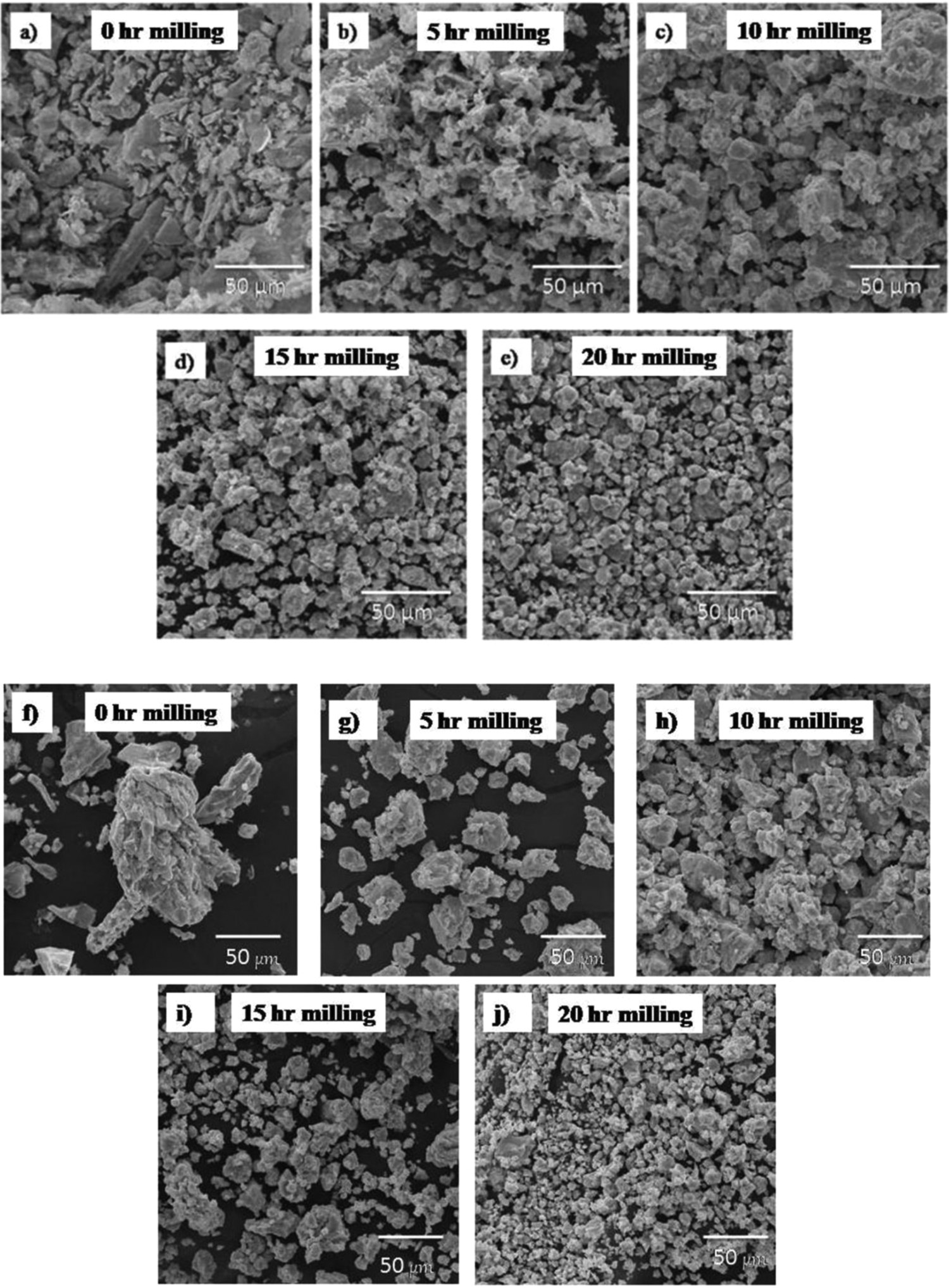
Evolution of structures for the milled powders
Figure 2 represents the XRD pattern for both the samples which was developed from pre-alloyed powders for different milling hours during MA. Extend of alloying which took place along with the phase evolution can be interpreted from the XRD pattern. FCC and BCC phases of iron represented as γ and α, respectively, were visible during the commencement of milling. Further milling of pre-alloyed mixtures reveals the diminishment of peaks which was clearly evident from 10 h of milling as a result of solid solution formation. The formation of the solid solution after 10 h of milling still had the presence of the BCC structure, while milling for 15 h resulted in the FCC structured transformation. A complete phase change to FCC structure is seen after 20 h of milling. As the presence of Y2O3 is 0.3 wt-% in the present mixture, its peak was not evident. The formation of the solid solution was accelerated as a result of the hard and brittle nature of ODS with very little addition. This is because of repeated fracturing and work hardening process due to MA. The presence of austenitic stabilisers like Mn and Ni also enhanced the formation of solid solution with the FCC structure [29]. Austenitic (γ) phase was formed as milling took place for 20 h and availability of Ni in the composition. Enayati and Bafandeh studied the formation of BCC structure after 60 h of milling when compared with our study [30]. In the present work, vials and balls were of stainless steel which impart high energy during MA to the pre-alloyed mixtures. The powder to ball ratio is 1:10 in our present study, while the work conducted by Enayati and Bafandeh had the powder to ball ratio of 1:6 [30]. It is evident that the formation of the nanocrystalline structure relies mainly on the milling parameters based on the work done by Pabi et al. [31].
XRD patterns of (a) sample A and (b) sample B developed from ferroalloys.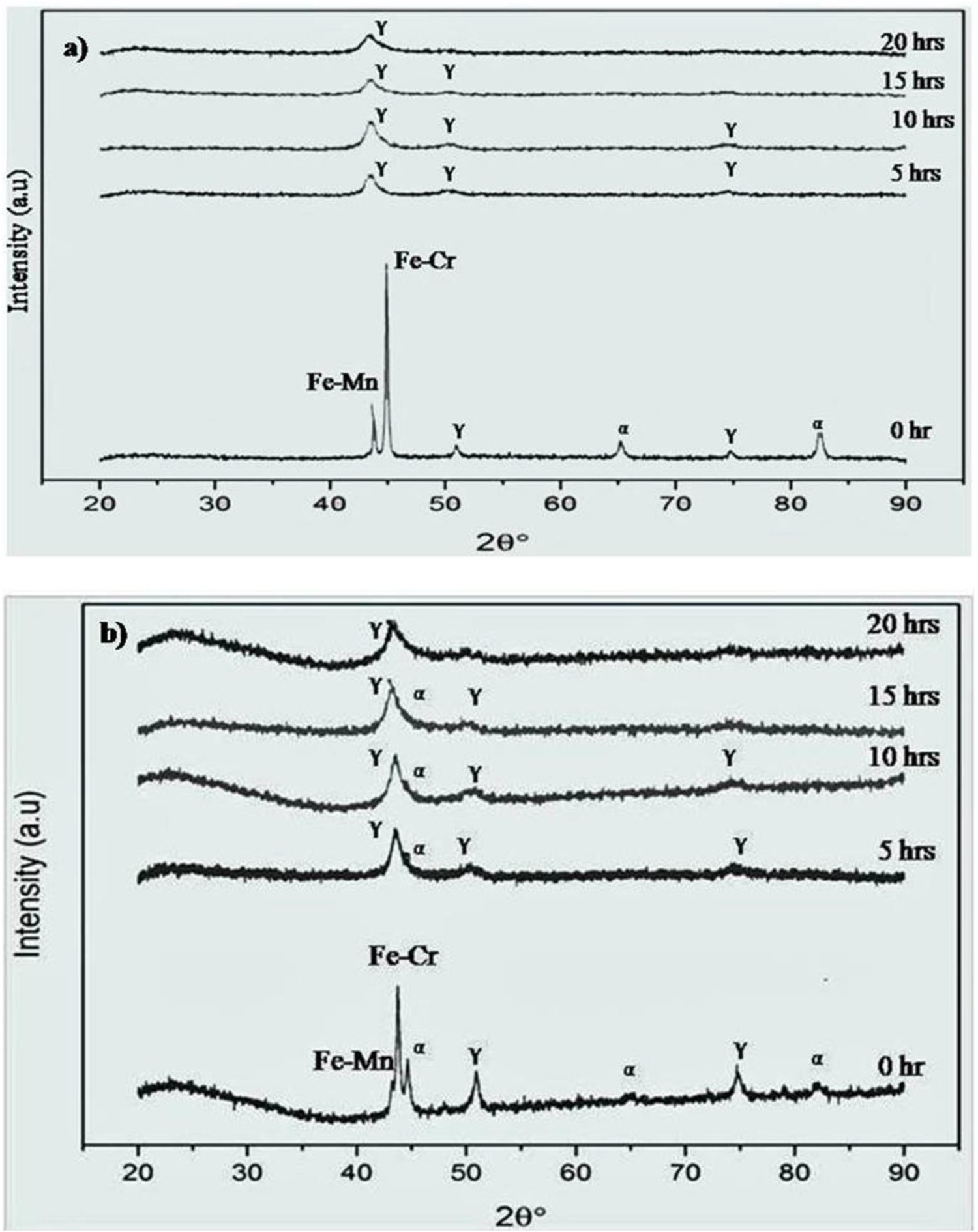
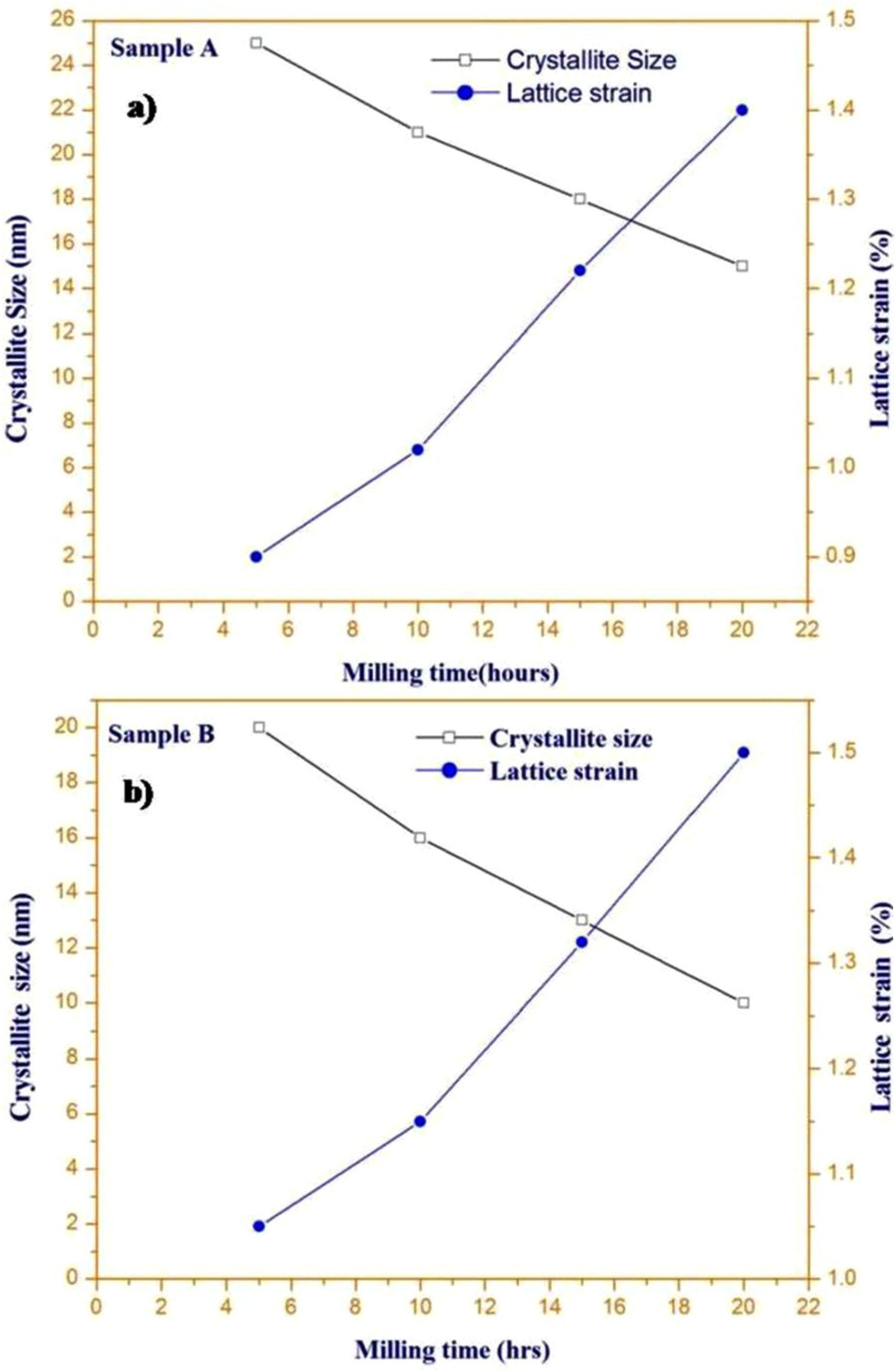
Figure 3 represents the variation in size of the crystallite and strain within the lattice for both sample A and sample B with regards to time taken for milling. Evaluation for lattice strain and crystallite size was employed by using the Williamson–Hall equation [32]. The crystallite size and lattice strain were calculated as a function of 2θ with respect to peak broadening from the XRD data based on the following equation:
Variation in lattice strain and crystallite size for sample A and B with respect to milling time.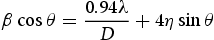
Evaluation of density for sintered samples
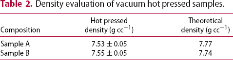
Density evaluation of vacuum hot pressed samples.
Microstructural analysis of the consolidated samples
The optical micrograph for both the samples is shown in Figure 4(a,b), respectively. The heterogeneous dispersion of metal carbides (dark region) along with γ phase is visible from the microstructure irrespective of the composition of the alloys. Pores are not visible as the temperature of sintering is around 1200°C. Sintering at initial stages does not have grain growth at a faster rate. Pores were rounded off as the sintering took place at higher temperatures. The process of sintering is volume diffusion while the grain boundary acts as vacancy sinks. At high temperatures, sintering pore coalescence occurs within grain boundaries which act as pinning points and grain growth is observed. Large vacancies are not observed due to increase in grain size during sintering, where the pore structures are rounded off which act as a significant phenomenon for pore removal [36]. Densification of samples at high temperatures is due to volume diffusion and grain growth. The theoretical density as well as sintered sample density is nearer values which are in concurrence with the densification studies. Apart from the austenitic grain structure, there is the presence of transgranular precipitates near the grain boundaries which is similar to the shape of pearlite structure which was observed as an alternate arrangement between austenitic grains. These precipitates are called false pearlite structure by some researchers [37,38]. These types of precipitates are seen near the grain boundaries in heat-resistant alloys which contain base material as chromium, nickel and iron. The SEM-EDS analysis will be further used to study the presence of constituent elements within the metal matrix. Grain boundaries are predominantly occupied by carbides. Grain boundaries are the region of highest diffusivity where these carbide particles disperse. The microstructure of the samples was unveiled after etching the samples under ferric chloride solution.
Optical micrograph of (a) sample A and (b) sample B.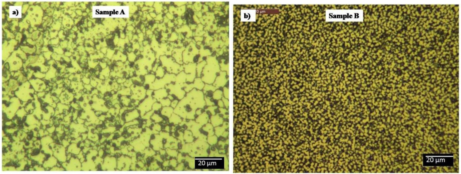
SEM-EDS studies
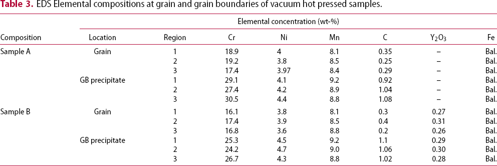
Grain and its boundaries for both the samples with and without the addition of Y2O3, respectively, were analyzed using SEM-EDS. Microstructure of sample A consists of equiaxed grains as shown in Figure 5(a,b). While with the addition of Y2O3 in sample B got the grain structure refined as shown in Figure 5(c,d). The measurement of elemental concentration within the grain and along its boundaries is shown in Table 3. Irrespective of elemental composition of the alloys, it can be noticed that the wt-% of chromium and carbon are altering within the grains and as well as along its boundaries from the analysis of EDS. In the current study, the sintered samples were cooled at 25°C min−1, which is lower when compared with the critical cooling rate of iron–chromium–nickel alloys to avert the carbide formation along the grain boundaries [39]. Kishore et al. investigated on the formation of grain boundary precipitates during conventional sintering of austenitic stainless steel dispersed with 1 wt-% Y2O3. During sintering, the cooling rate played an important role in the formation of grain boundary precipitates. Slower cooling time (10°C min−1) provided ample time for the formation of precipitates. The resultant microstructure had heterogeneous distribution of precipitates which resulted in lower density of the sintered samples [40]. From Table 3, it is visible the depletion of Cr within the composition (16–19%) when compared with its designated concentration of 21%. However, the concentration of Mn and Ni contents was at required levels both within the grain and also along its boundaries. With respect to EDS results as listed in Table 3, the depletion of Cr inside the grains affirms the existence of M23C6 metal carbides along the grain boundaries. The presence of M23C6 carbide formed is predominantly globular which is occasionally visible along the boundaries of the grain. The presence of these metal carbides was also confirmed through the XRD as shown Figure 6 which increases the hardness of material at elevated temperatures. Few researchers studied the development of austenitic stainless steel, as dispersed with Y2O3. Karak et Al. developed 304 L austenitic stainless steel dispersed with 1 wt-% Y2O3 [41]. SEM-EDS studies revealed the formation of ferrite phase which is due to the presence of high chromium content. A similar kind of results was reported in the present study because of higher chromium content.
SEM-EDS analysis of (a) sample A at the grain, (b) sample A at the grain boundaries, (c) sample B at the grain and (d) sample B at the grain boundaries. XRD pattern for the sintered sample. EDS Elemental compositions at grain and grain boundaries of vacuum hot pressed samples.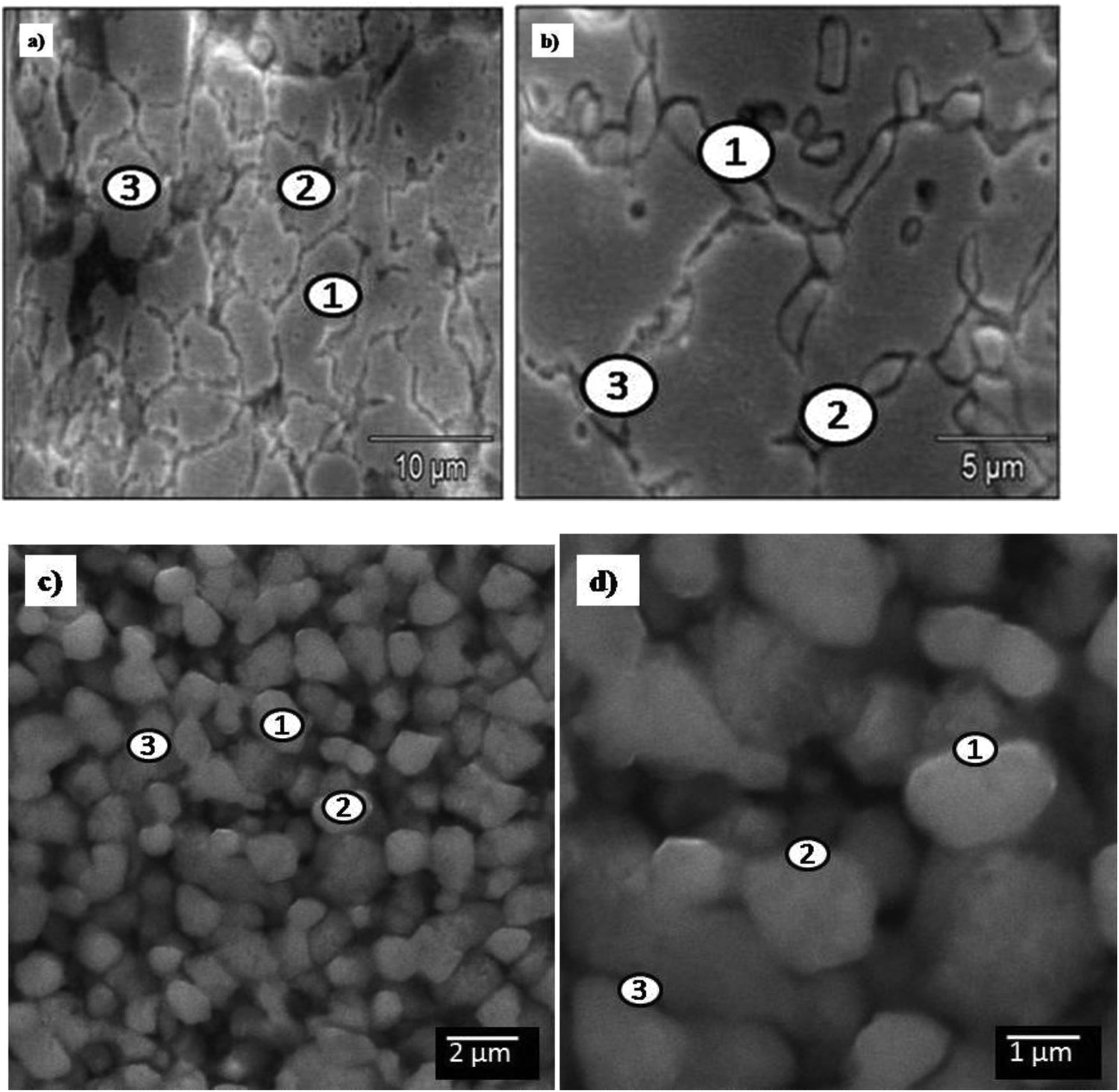
XRD of sintered samples
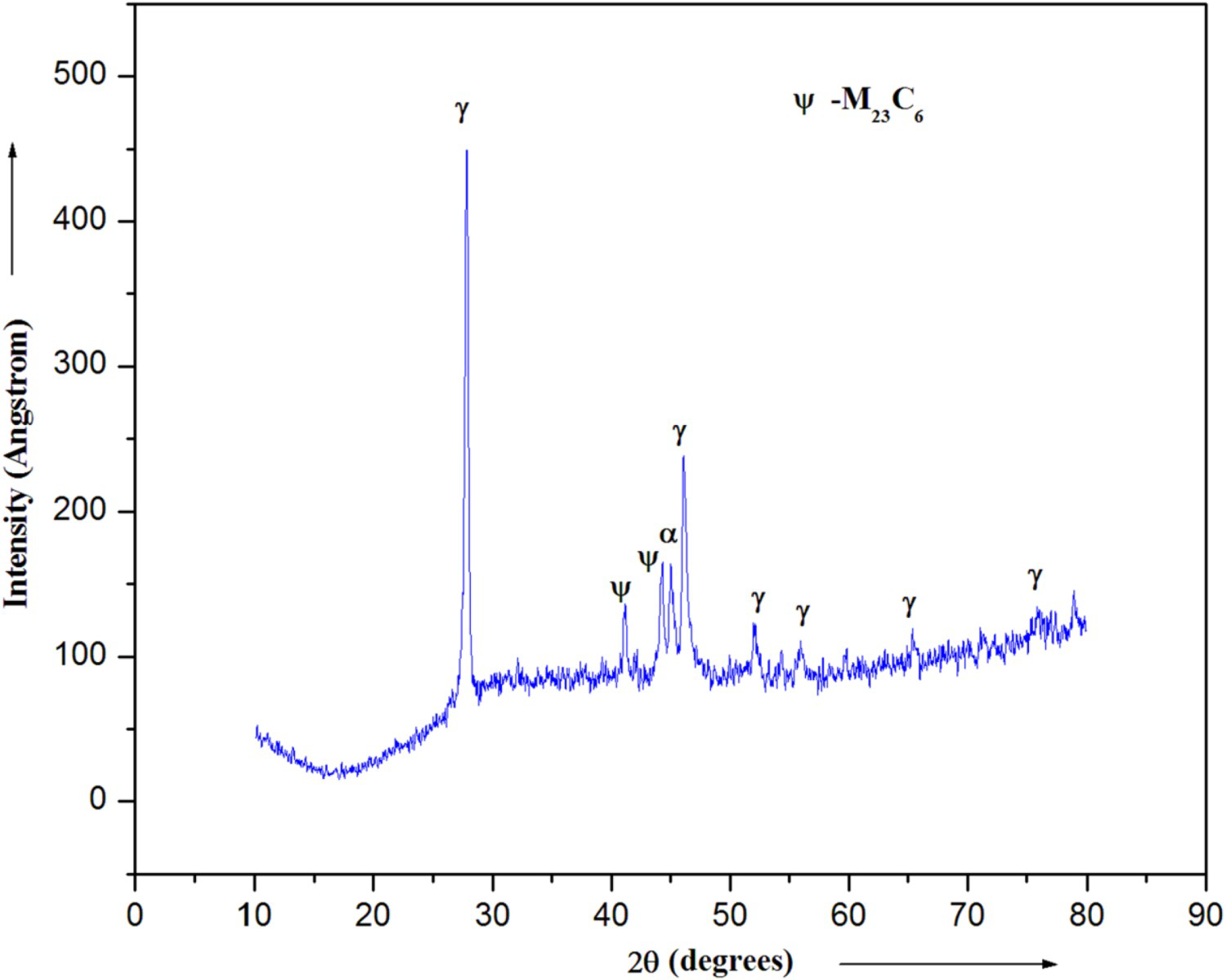
XRD analysis of the vacuum hot pressed samples predominantly exhibits diffraction peaks of austenitic structure as shown in Figure 6. The presence of Y2O3 peaks is not visible in the diffraction pattern of the sintered samples because of the small quantity and nanoparticle size (∼10 nm). The presence of small diffraction α peak is due to the presence of rich chromium content during the initial stages of MA and subsequent consolidation at the temperature of 1200°C. Similar results were reported by Wang et al. during the development of ODS dispersed austenitic stainless steel [42]. Few peaks of metal carbides (M23C6) were also detected where M represents chromium, manganese and iron [43]. The formation of carbides is mainly due to the higher C/Cr ratio. From the metallographic studies, it can be understood that these M23C6 nucleates very easily at the beginning when compared with other types of carbides. Moreover, the structural shape of these metal carbides is of a globular or cellular type. These carbide precipitates are usually observed near the grain boundaries due to the favourable place, as carbon having an interstitial solid solution capability which rapidly diffuses near the grain boundaries. However, the XRD analysis of the MA powders is free from metal carbide precipitates. The intensity of austenite peaks is dominant when compared with M23C6 peaks. The formation of M23C6 peak in hot pressed samples is due to slow cooling in the sintering cycle (25°C min−1). It can also be seen that with reduction in crystallite size of the MA powders and grain size of the austenitic sample, the amount of M23C6 formation is restricted. During the sintering of MA powders at 1200°C, the peaks of austenite became intense and shaped with diminished peaks of M23C6.
Transmission electron microscopy
The TEM micrographs for both the samples are shown in Figure 7(a,d), respectively, which were vacuum hot pressed at 1200°C. From Figure 7(a), austenitic twins are visible from the micrograph after vacuum hot pressing. FCC alloys revealed the presence of annealed twins due to the presence of low stacking fault energy followed by cold deformation and annealing. The SAD pattern indicates the formation of nanostructured FCC structure as shown in Figure 7(b). Dissolution of Mn and Ni in the austenitic structure resulted in the bright ring structure near the (111) within the SAD pattern. The FCC transformation is favoured due to nano-metric scale and refinement of structures. The grain size of the TEM samples are determined by the method of linear intercept as per equation (2),
TEM micrographs of vacuum hot pressed sample (a) bright-field image of sample A, (b) SAD pattern of sample A, (c) grain size distribution of sample A, (d) bright-field image of sample B showing nanocrystalline grains along with nano dispersoids of Y2O3, (e) SAD pattern of sample B, (f) grain size distribution of sample B and (g) diameter of nano dispersoids of Y2O3 in sample B.
 , the shape factor for spherical grains is assumed as 1.5
  , value 1 is assigned for distribution factor
  and the average length of intercept as
  . Figure 7(c) shows grain of equiaxed where size ranges from 0.3 to 1.4 µm when visualised through the TEM micrograph, with a mean grain size of 1 µm.
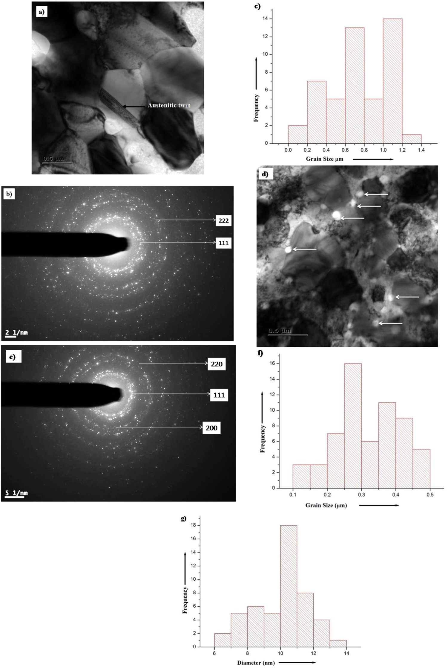
The TEM micrograph of sample B is shown in Figure 7(d) which contains 0.3 wt-% of Y2O3 within the metal matrix which consists of nanocrystalline grains. The formation of the nanocrystalline grains is also affirmed through the SAD pattern as shown in Figure 7(e). Similarly, the SAD pattern confirms the formation of the metal matrix with the FCC structure and the nano-Y2O3 particles are reflected from (220). The presence of Y2O3 is evident from the TEM micrograph. The average size of the Y2O3 particles was 10 nm as shown in Figure 7(g), which is uniformly distributed within the alloy. The dislocation lines were also seen near the Y2O3 particles due to the zener pinning phenomenon which resists the movement through dislocation. Figure 7(f) shows the analysis of distribution of grain size for sample B where a mean grain size of 0.3 µm is obtained. The grain size for sample B is correspondingly low in comparison with sample A. This is due to the addition of Y2O3 within the metal matrix. The grain growth stimulation took place in the microstructure containing yttria-rich particles as a result of sintering [44]. When compared with sample A, the sample B had newer grains due to grain growth stimulation phenomenon. Reduction of the grain boundary area is due to restriction of drag along the boundaries when it intersects yttria particles. To obtain reduced surface area and lower-sized powder particles, one of the best possible ways is through the MA process. The presence of stable oxide particles within iron–chromium–nickel alloys prevents sliding of grain boundary and motion due to dislocation due to pinning effect were reported by several researchers [42,45,46]. The precipitation of nano-oxide particles is observed after vacuum hot pressing at 1200°C. It can be observed that oxide particles disperse homogeneously within the metal matrix and the density of dispersions vary from region to region along the grain boundaries. High magnification studies reveal the nanoprecipitate particles have a faceted shape. Several researchers reported the formation of nano-dispersion of ODS in austenitic stainless steel. Nano-Y2O3 was dispersed in austenitic stainless steel by Chandradekhar et al. to obtain ultrafine dispersoids which was developed using the hot extrusion process. The TEM analysis of consolidated samples revealed a mean grain size of 0.3 µm and particle size of ∼7.5 ± 3.2 nm which is similar to the values obtained in our current study [47]. The development of austenitc ODS steel by Kishore et al. had a bimodal distribution of grains within the microstructure where the size of the grain, ranges from 200 nm to 1 µm. Similarly, the size of the complex oxide (Y–Ti–O) formed is found to be around 14 nm. The slight increase in size of the grain and particles is as a result of milling carried out for lesser duration of time for about 5 h [40]. Studies show that the lower milling time resulted in the formation of agglomeration of Y2O3 within the metal matrix and coarse grain. A similar kind of results was reported by Balazsi et al. with the development of 0.3 wt-% Y2O3 in austenitic stainless steel (316L) with an average grain size of the sintered samples was of 40–100 µm [48].
Comparison between different austenitic ODS stainless steel with respect to the different processing route.
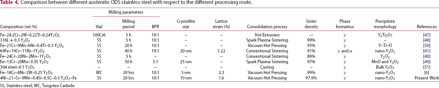
SS, Stainless steel; WC, Tungsten Carbide.
Conclusion
Required composition of austenitic stainless steel was developed with and without the addition of Y2O3 from pre-alloyed mixtures through MA and final consolidation done through vacuum hot pressing was investigated.
Very little deformation due to plasticity was observed through the SEM analysis for the MA powders during the initial stages of milling. Similarly, there was no evidence of agglomeration among the particles at the beginning stages of milling. The decrease in size of the powder particles was observed as the milling time increased as a result of the fragmentation. The cold working of the particles was predominant when compared with deformation of particles. The XRD analysis confirmed the overall shift to the FCC crystal structure by the end of 20 h of milling. The formation of the solid solution was accelerated due to the addition of ODS to the pre-alloyed mixture. A decrease in crystallite size can be attributed to an increase in milling time. The addition of yttria led to the accumulation of strain in sample B which resulted in higher lattice strain. In comparison to theoretical density, the vacuum hot pressed samples show 97.9% density. The presence of nanocrystalline grains led to a higher diffusivity and surface energy. Advantages in reduced particle size lead to attainment of high density compacts during sintering as lattice and grain boundary diffusion are reciprocal to particle size. The SEM-EDS analysis revealed the formation of fine grain structure for sample B with the addition of Y2O3. During sintering in lower cooling rates led to the formation of metal carbides with the depletion of chromium and accumulated along the grain boundaries which was also confirmed through the XRD analysis of the sintered sample. The addition of Y2O3 particles resulted in the formation of very fine grain structure within the alloy for sample B. Accumulation of metal carbides along the grain boundary is due to depletion of Cr from the metal matrix due to the lower cooling rate during sintering. During the TEM analysis for both the samples, austenitic twins were present. The addition of yttria in the metal matrix resulted in the decrease in mean grain size. Similarly with the addition of yttria particles, it led to the restriction of grain growth as the grain boundary intersects with the Y2O3 particles.
Footnotes
Disclosure statement
No potential conflict of interest was reported by the author(s).