
Abstract
A TC4/TiAl bimetallic structure (BS) was successfully fabricated by laser additive manufacturing (LAM) to investigate the microstructure evolution of the transition zone. The results presented that the microstructures of the transition zone consisted of α (α-Ti), α2 (Ti3Al) and γ (TiAl). The evolution rule of the microstructures was (more α + less α2) → (more α2 + less γ) → (more γ + less α2) from the TC4 alloy side to the TiAl alloy side in the transition zone. The mechanical properties of the LAMed BS specimens revealed that the tensile strength reached that of the as-deposited TiAl alloy. The fracture was located at the TiAl alloy side near the transition zone and the fracture surfaces showed a quasi-cleavage fracture morphology.
Keywords
Introduction
Weight reduction is a vital parameter in the design and manufacture of parts and components for aerospace applications [1]. Ti alloys have been widely used because of their high specific strength and other advantageous characteristics [2]. In recent years, TiAl-based intermetallic compounds have attracted wide attention in aerospace engineering because of their low density, high specific strength and excellent high temperature properties [3,4]. These excellent properties make these alloys potential substitutes for nickel-based superalloys in aerospace parts or high-temperature structural applications [5]. However, the application of integral TiAl alloys has some limitations, meaning that further research is required in order to fully develop the combination of TiAl alloys with other materials [6].
Although some researchers have carried out significant work on diffusion welding, fusion welding, friction welding and other aspects of bimetallic structure (BS) materials, due to the existence of defects, brittle phases and residual stress in the joint [7-10], the joint has high crack sensitivity, which limits the further application of TiAl alloys. In order to solve the above problems, the laser additive manufacturing (LAM) is an ideal manufacturing method for preparing BS parts with complex shapes [11]. In recent years, researchers have made some progress in the fabrication of Ti/TiAl bimetallic alloy structures using the LAM method. For example, Qu et al. [12] successfully prepared a Ti–47Al–2.5V–Cr/Ti–6Al–2Zr–Mo–V BS material without metallurgical defects by a LAM technique. Zhang [13] and Xu [14] also successfully prepared Ti2AlNb/TC11 and γ-TiAl/TC11 BSs using the LAM method and analysed the microstructure and tensile properties at room temperature. However, the direct connection of TC4/TiAl BS is rarely reported in detail using the LAM technique.
In this study, to provide a new candidate material for practical applications of integral turbine blade disks (Figure 1(a)), the good metallurgical joints of TC4 (Ti6Al4V)/TiAl (Ti48Al2Cr2Nb) BS was successfully fabricated by the LAM method, and the appearance of the specimen is shown in Figure 1(b). To evaluate the TC4/TiAl interface, the microstructure and mechanical properties of the BS were characterised. The experimental results can provide the theoretical basis for manufacturing BS parts.
(a) Schematic showing the LAMed TC4/TiAl BS aeroengine turbine blade; (b) macrograph of the TC4/TiAl BS specimen; (c) geometry and dimension (mm) of the tensile specimen.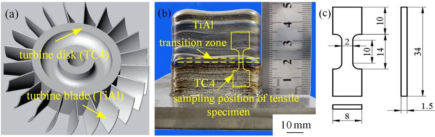
Experimental procedures
Ti–6Al–4V (TC4) and Ti–48Al–2Cr–2Nb (TiAl) alloy powders were produced by Zhonghang Maite Powder Metallurgical Technology Co. Ltd. (Beijing, China). The particle size of the gas atomised powder is 53–150 μm. The chemical composition of the TC4 alloy powder (wt-%) is 6.04 Al, 3.82 V, 0.16 O, 0.03 N and the balance of Ti. TiAl alloy contains (wt-%) 32.5 Al, 4.62 Nb, 2.64 Cr, 0.06 O, 0.005 N and the balance is Ti. Before the test, the powder was placed in a vacuum drying box and dried at 150°C for 2 h. The TC4 alloy was used as a substrate material, with a size of 100 mm × 100 mm × 10 mm. Before the test, the oxide film and dirt on the surface of the substrate were removed by a grinder and wiped clean with acetone.
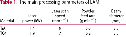
The main processing parameters of LAM.
The EBSD specimens are grinded on SiC grit paper and then polished by standard mechanical polishing. Subsequently, they are etched in a mixture solution of HF, HNO3 and H2O with a volume ratio of 1:6:60 and a etching time of 5–15 s. Scanning electron microscopy (SEM) with an S3400 and a SU8010 field emission scanning electron microscope is used to characterise the microstructure and fracture morphology of the BS. The EBSD processing parameter with a step size of 0.4 μm was conducted by adopting a Gemini SEM300. The chemical composition analysis was performed using energy-dispersive X-ray spectroscopy (EDS) on the same system as the SEM. The microhardness of the transition zone is determined using an HVS-1000 microhardness tester with a 10 s loading time and under a load of 300 g. The room temperature tensile property of the BS in the build-up direction is evaluated using a WDW-100 universal electronic tester at a loading rate of 0.5 mm min−1. The specific size of tensile testpieces and the tensile direction are presented in Figure 1(c).
Results and discussion
Element distribution of TC4/TiAl interface was measured using EDS and the relevant results were shown in Figure 2. The line scanning results of the transition zone show that the main elements of Al and Ti gradually transition from TC4 to TiAl alloy, indicating that the joint of TC4 and TiAl alloy has reached metallurgical bonding. Due to the gradual transition of Al element contents in the transition zone, the Al element contents passed through the α2 phase region shown in Figure 3, and finally, a large number of α2 phases were formed in the microstructure of the transition zone.
Variation of composition across the transition zone. Phase diagram of the Ti–Al binary alloys.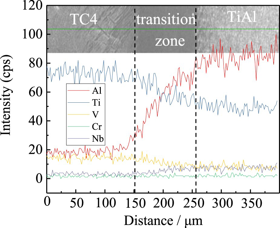
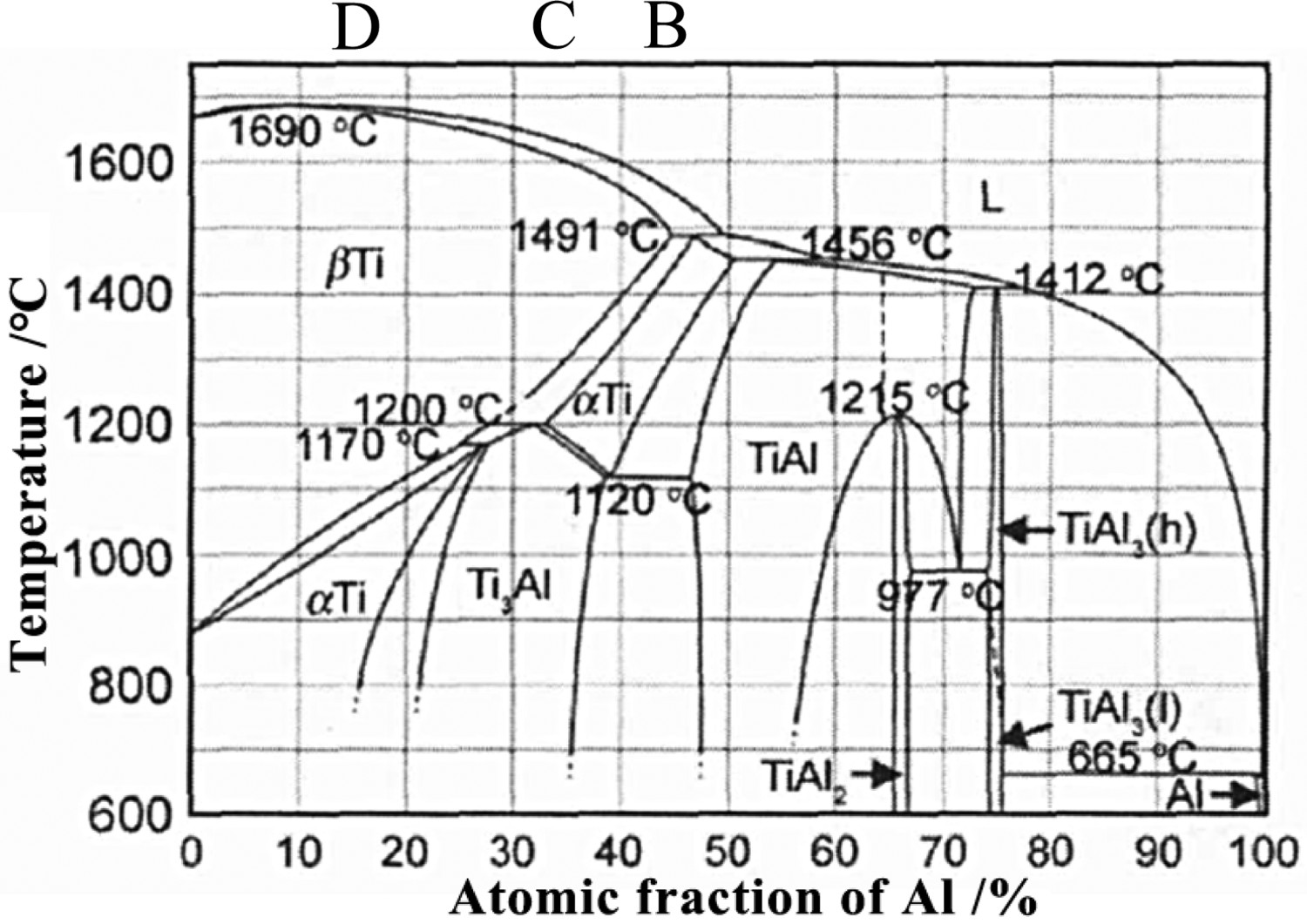
Figure 4 shows the microstructures of the transition zone. From Figure 4(a), the overall morphology of the TC4/TiAl BS can be observed. The microstructures of the B, C and D markers in the diagram are shown in Figure 4(b–d), respectively. The results of the EDS analysis show that the Al components of the D, C and B markers were ∼15, 34 and 43 at.-%, respectively. Figure 4(b) shows the microstructure and morphology of the TiAl alloy side near the transition zone. Many pore defects can be observed in the deposits of the TiAl alloys and the microstructure shows a lamellar shape. The microstructures of the TiAl alloy side near the transition zone are composed of short rodlike grains and grain boundaries, and there is a clear interface between the TiAl alloys and the transition zone. Figure 4(c) shows the microstructure of the central region of the transition zone with short rodlike grains and grain boundaries. Figure 4(d) shows the microstructures of short rodlike grains and grain boundaries in the transition zone near the TC4 alloy side. At the interface between the TC4 alloy and the transition zone, the grains in the transition zone grow along the grain epitaxy of TC4 alloy, because the grain epitaxy greatly reduces the nucleation energy.
(a) SEM image of the TC4/TiAl BS; (b) microstructures of the TiAl alloy side near the transition zone; (c) microstructures of the transition zone; (d) microstructures of the TC4 alloy side near the transition zone.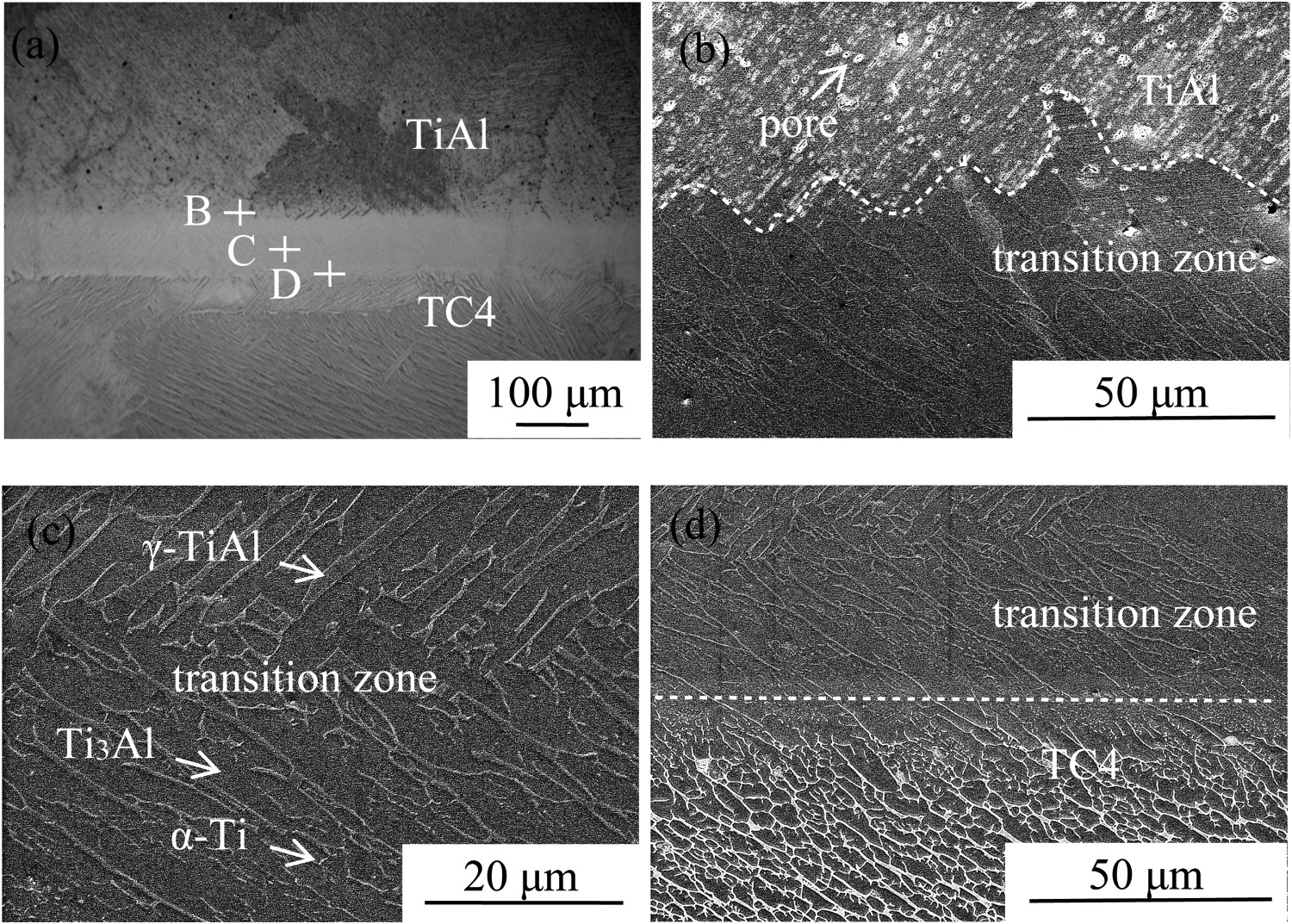
XRD is used to determine the phase compositions at different positions of the TC4/TiAl interface and the results are shown in Figure 5. As can be seen from Figure 5, the top diffraction curve is on the TiAl alloy side near the transition zone, the middle curve is the centre of the transition zone and the bottom curve is on the TC4 alloy side near the transition zone. It can be seen from Figure 5 that the microstructures were mainly composed of α-Ti, α2 and γ phases. From the TC4 alloy side to the TiAl alloy side in the transition zone, the peak intensities of the (101) α-Ti phase at ∼40° became lower and lower, while the diffraction peaks of the (111) γ phase became higher and higher. The results revealed that the contents of α-Ti phase were the most in the TC4 alloy side, and the contents of γ phase were the most in the TiAl alloy side. When the 2θ angle was ∼79°, the diffraction peak of the (401) α2 phase in the transition zone centre was the highest, and thus the contents of α2 phase were the most compared with the TC4 alloy side and the TiAl alloy side.
XRD diffraction pattern of the LAMed BS.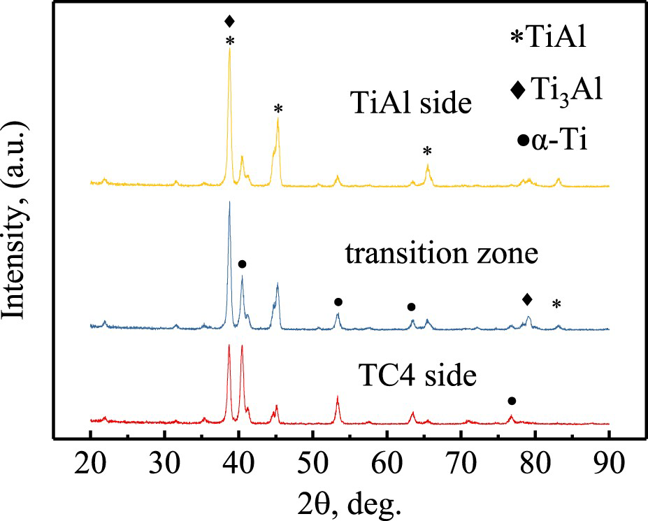
Ti-Al phase diagram shown in Figure 3 (in which composition range of specimen 1, specimen 2, specimen 3, and specimen 4 separately labelled by 1, 2, 3, and 4 grey areas) can provide information on phase transitions occurring with the alloys during cooling.
The change of Al element contents from low to high (D-point → C-point → B-point) is represented by three vertical lines, D, C and B, as shown in Figure 3, respectively. And Points B, C and D correspond to the results of EBSD analysis in Figure 6(c–d), respectively. The SEM backscattered images, including the TiAl alloy, transition zone and TC4 alloy, are shown in Figure 6(a). The EBSD analysis results of the B point with a high Al content near the TiAl alloy side in the transition zone are shown in Figure 6(b), with the microstructure consisting of a large amount of γ phase and a small amount of α2 phase. The EBSD analysis results of the C point at the centre of the transition zone are shown in Figure 6(c), where the microstructure consists of a large amount of α2 phase and a small amount of γ phase. The D point near the TC4 alloy side in the transition zone shows that the microstructure is composed of a large amount of α phase and a small amount of α2 phase, as shown in Figure 6(d). The evolution of the above-mentioned phases depends on the gradient change of Al element contents.
(a) SEM backscattered image across the transition zone; (b–d) phase distribution of the EBSD result in the TiAl/transition, transition and transition/TC4 interfaces, respectively.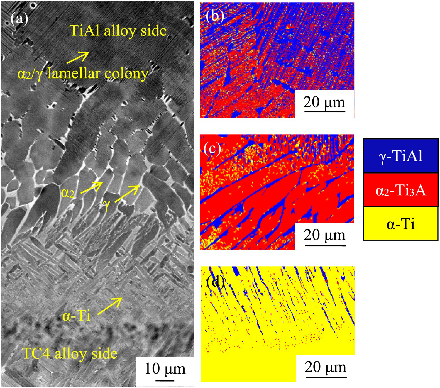
Vickers microhardness crosses the three regions along the deposition direction was also performed to evaluate mechanical property of the transition zone, as shown in Figure 7. On the TC4 alloy side, the hardness values of the deposited sample are basically stable at ∼350 HV, and the result is similar to that in reference [15]. In the transition zone, the hardness values increase compared with the TC4 and the TiAl alloy, and its values reach ∼460 HV. The main reason is that the Al element in the TiAl alloy is diluted, resulting in the formation of a large number of α2 phases, and the analytical results are consistent with those in Figure 6(c). The α2 phase is an ordered hexagonal structure with less dislocation slip surface, so its hardness value is higher. On the TiAl alloy side, the hardness values of the as-deposited specimen remain stable, and its values are ∼420 HV. The results are consistent with the results of previous research [16].
Microhardness profiles along deposited direction.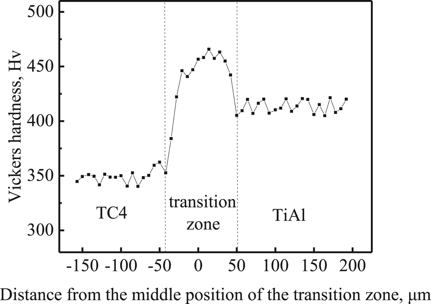
The fracture position and tensile stress–strain curve of TC4/TiAl BS at room temperature is presented in Figure 8(a,b). From the test results, the tensile curve presents a sudden break without obvious yielding stage, which is a typical fracture characteristic of brittle materials. The average ultimate tensile strength and elongation are ∼436 MPa and 1.1%. The tensile strength and elongation of deposited TiAl alloy at room temperature are ∼410–450 MPa and 1.1% [17], so the strength of the joint reaches that of deposited TiAl alloy.
(a) Fracture position of the BS; (b) stress–strain curve of the tensile specimens; (c) morphology of the fracture surface (at.-%), Al 38.03; Ti 57.92; Nb 1.89; Cr 0.24; V 1.92.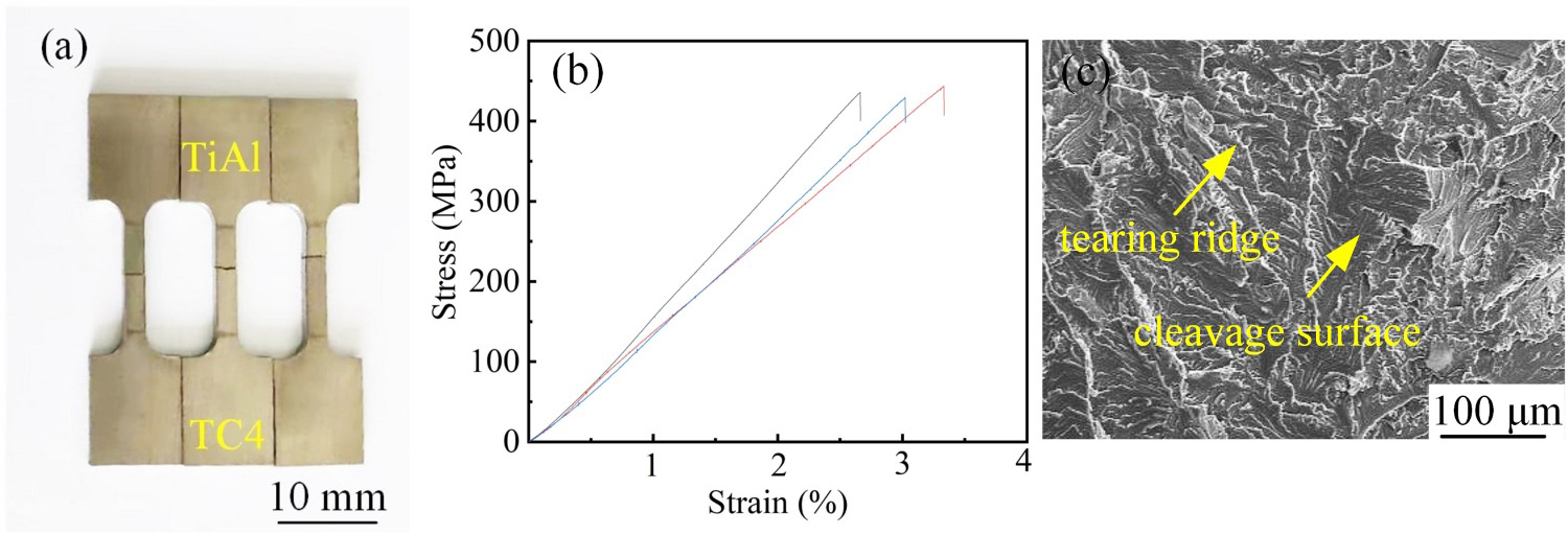
Compared with V as an interlayer [18], the tensile strength of directly connected TC4/TiAl alloy decreased from 476 to 436 MPa. Because a large number of short rodlike α2 phases are formed in the transition zone of directly connected TC4/TiA alloys, the hardness of α2 phase is obviously higher than that of TC4 and TiAl alloys. In addition, according to the fracture morphology, the proportion of cleavage surface also increased, so the tensile strength of directly connected TC4/TiAl alloy decreased. However, the addition of V layer will increase the cost of materials.
The location of tensile fracture is mainly related to microstructures, stress and defects [19,20]. First, there is a lot of α2 phase in the transition zone, which gives the transition zone higher strength than TiAl alloy because the hardness value of α2 phase is higher than γ phase. Second, because the two materials of TC4 and TiAl alloys have the different thermal expansion coefficients, the internal stress could be produced in the TC4/TiAl interface upon rapid cooling after deposition processing [21]. Thirdly, pore defects were observed in the TiAl alloy side, which could jeopardize the mechanical property of TiAl alloy to a certain extent. According to the above-mentioned analysis, the fracture location of the TC4/TiAl BS was inevitable on the TiAl alloy side, which was proven through the morphology and chemical compositions of the fractured surfaces presented in Figure 8(c). The fractured morphology shown in Figure 8(c) is composed of the tearing ridges and the cleavage surfaces, which can be identified as quasi-cleavage fracture mode.
Conclusions
In the study, the crack-free TC4/TiAl BS was successfully prepared using LAM, which is a potential application of TC4/TiAl BS in the aeroengine integral turbine blisk. The evolution rule of microstructures is (more α + less α2) → (more α2 + less γ) → (more γ + less α2) in the transition zone. The tensile strength of the LAM BS specimens was ∼436 MPa at room temperature, which reaches that of the as-deposited TiAl alloy. The fracture location was on the TiAl alloy side near the transition zone, in which the fracture surfaces are quasi-cleavage fracture mode.
Footnotes
Disclosure statement
No potential conflict of interest was reported by the author(s).