
Abstract
The influence of the Cetrimonium bromide (CTAB) surfactant on the mechanism of electroless Ni–B deposition, corrosion, and scratch resistance of the resulting coatings was studied. Effect of different concentration of the surfactant on deposition rate and surface morphology was studied using SEM. Finally, the effect of an optimized concentration of CTAB surfactant on the surface chemistry, corrosion, and scratch resistance of the Ni–B coating was analysed using GDOES, potentiodynamic polarization, salt spray test, XPS, scratch test, SEM, and EDS. It was found that the CTAB surfactant increases the mass transfer and deposition rate of the coating. Adding CTAB surfactant in electroless solution significantly improves corrosion resistance by eliminating the pits formation at the surface and decreasing the number of defects at the interface which finally improves the formation of stable passive layer. Additionally, the highest scratch resistance was obtained when CTAB surfactant was added into the electroless Ni–B plating bath.
Introduction
In recent years, the electroless plating process has been widely used for nickel deposition. Ni electroless plating is divided into three groups: pure Ni, nickel–phosphorus (Ni–P), and nickel–boron (Ni–B) [1-3]. The difference between these three groups is the type of reducing agent. Using boron-containing reducing agents, such as aminoborane or sodium borohydride in electroless plating bath leads to electroless nickel–boron deposition [4-6].
Ni–B coatings are of special importance due to higher hardness and excellent tribological behaviour compared to Ni–P and Ni coatings [7-10]. Nevertheless, the demand for further improvement in the performance of these coatings necessitates continued research on Ni–B coatings.
One of the methods for improving the mechanical properties of the coating is adding particles such as Al2O3 [11], TiO2 [12], V2O5 [13], and CeO2 [14] as well as CNT [10] and graphene [15] into the electroless bath. However, in most cases adding particles increases the porosity of the coatings which leads to poorer protection ability. In addition, homogeneous distribution of particles on the substrate surface is hard to reach and requires a series of surface activation processes on the particles [16]. To solve this issue, one of the most common solutions is the addition of surfactants in the plating solution to improve the dispersion and stability of the particles [17-19].
Surfactants can change the wettability properties of the substrate and reduce the surface tension between hydrogen bubbles and the substrate during the deposition [20]. This phenomenon impacts the surface morphology, chemical composition, and properties of the coating [21,22].
Two opposing views have been reported regarding the effect of surfactant on deposition mechanism. In the first hypothesis, it is assumed that ionic surfactants are adsorbed at the solid/solution interface and form a stable monolayer. The formation of this monolayer will prevent direct contact of the electrolyte with the substrate and decrease the deposition rate [23]. On the second hypothesis, it is assumed that the hydrophobic interaction of two surfactants tails leads to the formation of a bilayer. As the interior of the bilayer is hydrophilic, water is drawn inside the bilayer and makes its formation unstable on the substrate surface. Therefore, in this point of view surfactants will not affect the deposition rate [24].
To clear up on these opposing points of view, the purpose of this study is to understand the role of CTAB surfactant (the most stable and low-cost cationic surfactant) on the mechanism of electroless Ni–B deposition. This research is divided into two parts. First, determining the optimal concentration of CTAB surfactant for electroless Ni–B plating and understanding the role of the surfactant on the deposition mechanism. Second, studying the effect of optimized concentration of CTAB surfactant on the chemical structure, corrosion behaviour and scratch resistance of Ni–B coating.
Materials and methods
Substrate preparation
The DIN 17100 St37 steel with dimensions of 50 × 25 × 1 mm3 was used as a substrate. All samples were ground up to 800 grits using SiC papers. Before deposition the substrates were degreased using acetone and etched in a 30 vol.-% HCL solution for one minute.
Electroless nickel-boron plating
Ni–B plating was processed at 95 ± 1°C temperature for 60 min. The bath was composed of nickel chloride, sodium borohydride, ethylenediamine, sodium hydroxide, and tin chloride. The chemistry of the solution was kept identical to the tin stabilized baths developed by Bonin et al [4]. Four concentrations of the CTAB surfactant (CMC, 5CMC, 10CMC, 20CMC), were used in the Ni–B plating bath. It should be noted that the critical micelle concentration (CMC) of CTAB in Ni–B solution was obtained using contact angle measurements.
Surfactant critical micelle concentration measurement
Contact angle measurements were carried out by OCA 15 plus system. The critical micellar concentration of the CTAB surfactant was determined by measuring the contact angle with respect to surfactant concentration of droplets of distilled water and electroless Ni–B solution on silica glass.
Deposition characterization
The surface morphology and the coating thickness were studied using A Hitachi SU8020 scanning electron microscope (SEM). Roughness measurements were carried out using a Zeiss Surfcom 1400D-3DF apparatus.
Chemical composition of the coatings was studied with GDOES (Glow Discharge Optical Emissions Spectroscopy) using a Horiba-Jobin–Yvon GD-Profiler.
Corrosion and scratch resistance
Corrosion characterization was performed by potentiodynamic polarization in 0.1 M NaCl solution using Bio-logic SP-50 potentiostat. A coated sample, platinum plate, and an Ag/AgCl electrode were used as working, counter, and reference electrodes, respectively. A potential range of −600–1000 mV from OCP, with 0.167 mV/s as scan rate, was applied to the working electrode. Both anodic and cathodic polarization branches were executed separately starting from OCP. Additionally, neutral salt spray tests were carried out according to ASTM B117-07. The tests were conducted for a period of 3, 5, and 7 days and the surface appearance of the corroded coatings was assessed by digital photographs.
The surface chemical properties of the corroded coatings were analysed using the X-ray photoelectron spectroscopy ESCA-5000 system after 7 days’ immersion in salt spray test.
A CSEM scratch tester machine with a diamond Rockwell stylus with a radius of 200 μm was used to study the adhesion and mechanical properties of the coatings. The linear increasing load from 0 to 150 N with a scratch velocity of 6.75 mm/min and a scratch distance of 10 mm was used for all samples. The scratched coatings were analysed using SEM, EDS.
Results and discussion
Determination of the CTAB critical micelle concentration
Figure 1 shows a diagram of the contact angle versus the surfactant concentration, which decreases with increasing concentration of the surfactant to a certain point, and then remains almost constant. This point is considered as the CMC of CTAB surfactant [25].
Evolution of contact angle with surfactant (CTAB) concentration in water and Ni–B solution.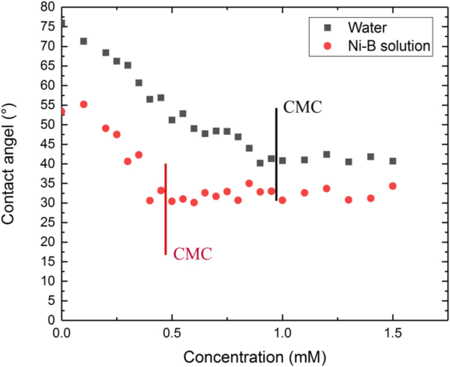
Results show that surfactant critical micelle concentration in Ni–B solution is lower compared to distilled water (0.4 and 0.9 mM respectively). This is due to the higher ionic strength in Ni–B solution which creates electrostatic attraction between the head groups of the surfactants. In fact, negatively charged anions in Ni–B solution decreases this repulsion force between surfactants by forming new electrostatic interactions [26] and leads to their rapid aggregation [27,28].
Based on the results of contact angle measurement, 0.4 mM was used as the CTAB critical micelle concentration in the electroless nickel–boron plating bath.
Surface morphology of the coatings
Figure 2 shows the surface morphology of samples. All of the samples show the cauliflower-like structure which is formed by an assemblage of nodular sub-colonies (Figure 2(a–f)). This nodular sub-colonies structure has been reported by many authors [27].
SEM surface morphology images of the (a) Ni–B, (b) Ni–B–CMC, (c) Ni–B–5CMC, (d) Ni–B–10CMC, (e) Ni–B–15CMC, (f) Ni–B–20CMC coatings.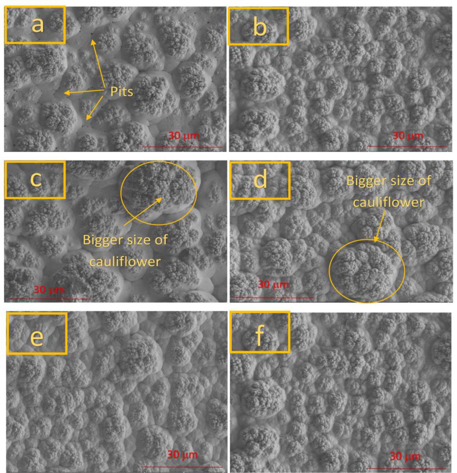
Cauliflower-like features with a bigger size (approximately 20–25 µm) were observed in the samples having 5CMC and 10CMC of CTAB (Figure 2(c,d)). The surface morphology of the Ni–B sample shows the presence of micro-pits on the sample, which are formed due to the hydrogen evolution reaction (Figure 2(a)). Hydrogen bubbles formed from the reduction reactions can be trapped on the asperities of the substrate surface as the deposition layer grow, and create pits or cracks [29,30] However, micro-pits were not observed on samples containing surfactant (Figure 2(b–f)). The absence of micro-pits on the samples made with CTAB surfactant is due to the fact that surfactant impedes hydrogen bubble incorporation into the coating.
Thickness of the coatings
Figure 3 shows the SEM images of cross-sections of as-plated coatings. The average thickness value of 10 measurements has been reported on the figures. Increasing surfactant concentration up to 5 times CMC increases the coating thickness from 16 to 21.8 µm (Figure 3(a–c)). The increment of thickness value might be due to fact that CTAB surfactant detaches hydrogen bubbles at the solid/liquid interface which facilitates the mass transfer of the reaction components. The absence of hydrogen bubbles linked with the increase of the surfactant concentration also reduces defects at the interface of the coating that is clearly observable in the case of Ni–B produced with CTAB surfactant (as seen on Figure 3(b–f). However, in the absence of CTAB surfactant defects are formed at the interface of the coating and substrate (Figure 3(a)). It can also be more clearly said that the bigger cauliflower-like structures of the 15 and 20 CMC coatings were due to the fact these coatings are thicker. In fact, higher deposition rate resulted in the formation of the bigger cauliflower-like structures. Interestingly, increasing the surfactant concentration from 5CMC up to 20CMC decreases the coating thickness significantly. As the surfactant concentration increases from 5CMC to 20CMC, a depletion–attraction phenomenon might occur due to the high density of the surfactant in the solution: when two surfactant micelles are approaching each other in a solution with a high concentration of surfactant, a third smaller surfactant micelle will no longer be able to fit in the space between the two bigger ones and so surfactant will be depleted from this space and as result osmotic pressure increases in this area. The increased osmotic pressure draws water from the surfactant-depleted region, thus attracting all surfactants toward each other [31,32]. This phenomenon causes surfactant aggregation which inhibits surfactants absorption on the surface of the bubbles and deaccelerated the ionic micro-convection speed.
Cross-sectional SEM images of the (a) Ni–B, (b) Ni–B–CMC, (c) Ni–B–5CMC, (d) Ni–B–10CMC, (e) Ni–B–15CMC, (f) Ni–B–20CMC coatings.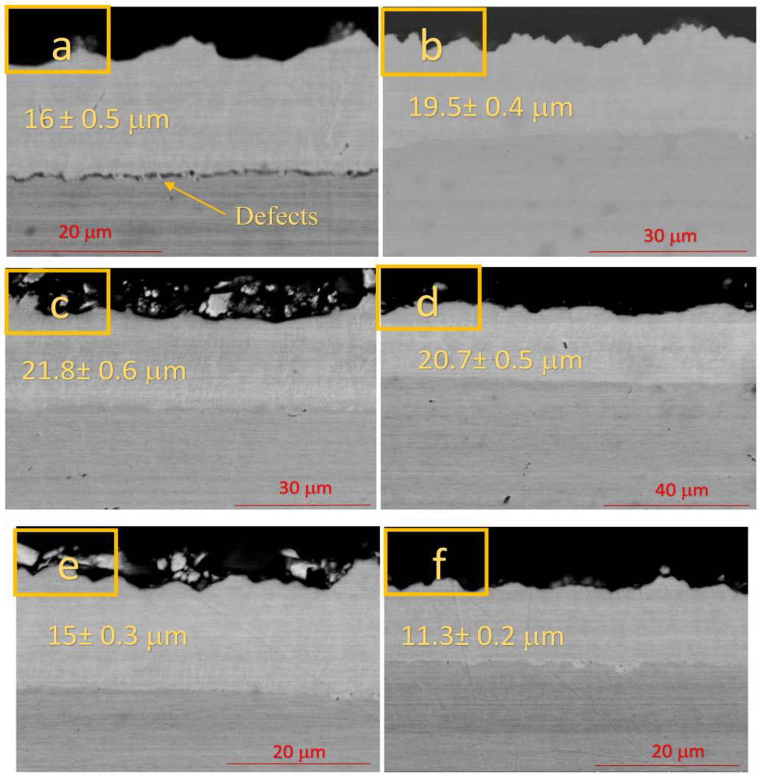
Roughness of the coatings
As shown in Figure 4, raising surfactant concentration to 20CMC has led to a significant decrease in the roughness of the samples. This is because the positive repulsion will be created between the hydrophilic head of CTAB surfactants and Ni2+ ions which transfer homogeneously Ni2+ at the interface of the coating and solution during deposition. As a result of homogeneous reduction of the Ni2+ ions on the surface, the surface roughness of the coating decreases.
Average surface roughness (Ra) results of the coatings.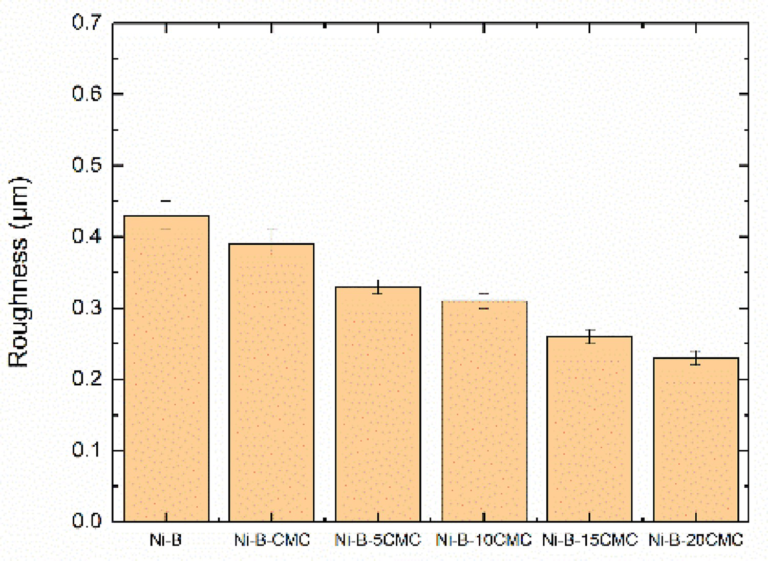
Based on the obtained results, a concentration of 5CMC is chosen as the optimized concentration of CTAB surfactant to be added into the Ni–B electroless bath because it presents the highest thickness without any defects. From this point of study, profile chemistry, scratch resistance, and corrosion behaviour of the Ni–B and Ni–B–5CMC will be characterized and discussed.
Profile chemistry
Figure 5 shows the depth profile chemical analysis, obtained by Glow-discharge Optical Emission Spectroscopy for Ni–B and Ni–B–5CMC coatings. In the Ni–B sample, at the interface the boron concentration is close to 4.5 wt-% and it decreases toward 4 wt-%. On other hand, for the Ni–B–5CMC sample, the concentration of boron close to the substrate is higher (4.8 wt-%) and it decreases to nearly 4.3 wt-%. It is assumed that, during the deposition process, the concentration gradient is the main driving force for the diffusion of nickel and borohydride ions towards the substrate. When the optimized concentration of CTAB surfactant is added to the electroless bath, the hydrophobic interaction between hydrophobic surfactant tails and the bubbles creates micro-convection and increases concentration gradient which transfer more borohydride ions on the substrate, leading to higher boron content in the coating.
GDOES depth profile chemical analysis of (a) Ni–B, and (b) Ni–B–5CMC coatings.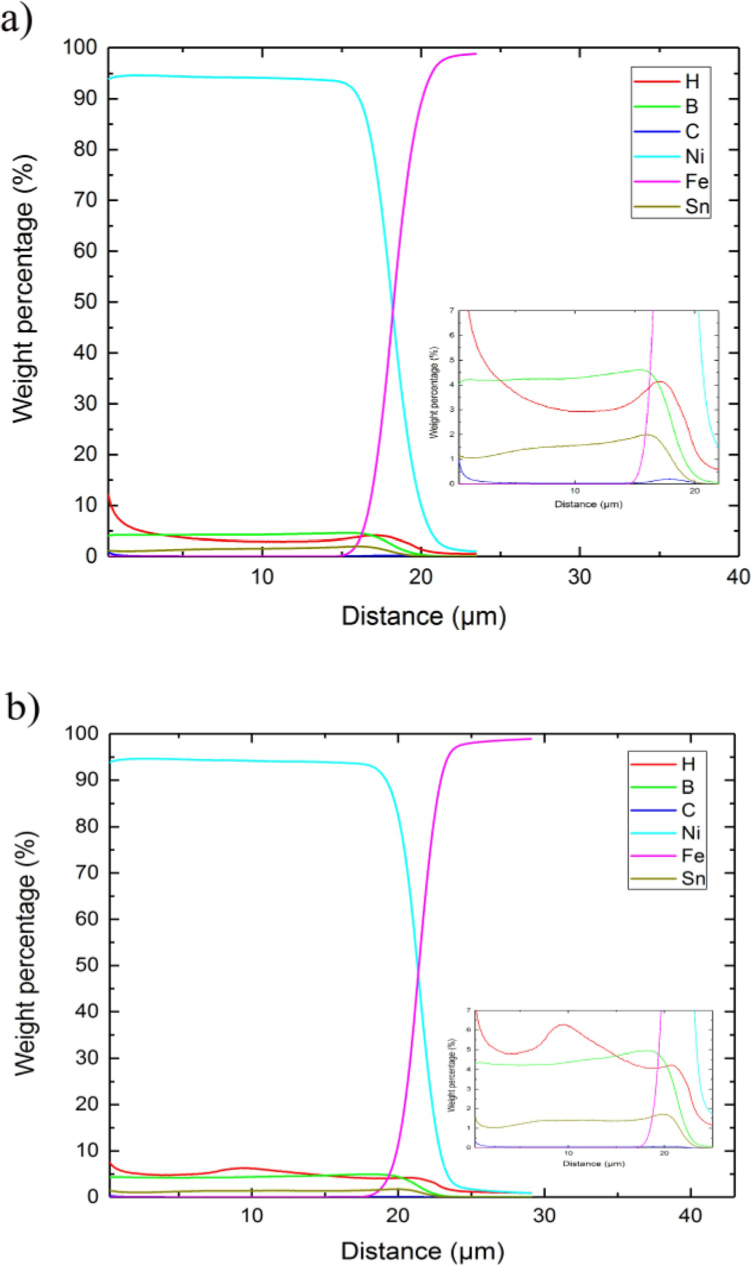
Microstructure of coating
Figure 6 shows the FIB image for the cross-sectional view of the Ni–B and Ni–B–5CMC samples. In the Ni–B coating, cauliflowers are formed sporadically and between cracks are formed between the features of the cauliflowers. Interestingly most of the cracks are formed in the same direction which is known as uphill growth direction. On the other hand, Ni–B–5CMC sample shows compact formation of the coating structure.
FIB-SEM image of the (a) Ni–B–5CMC and (b) Ni–B coatings.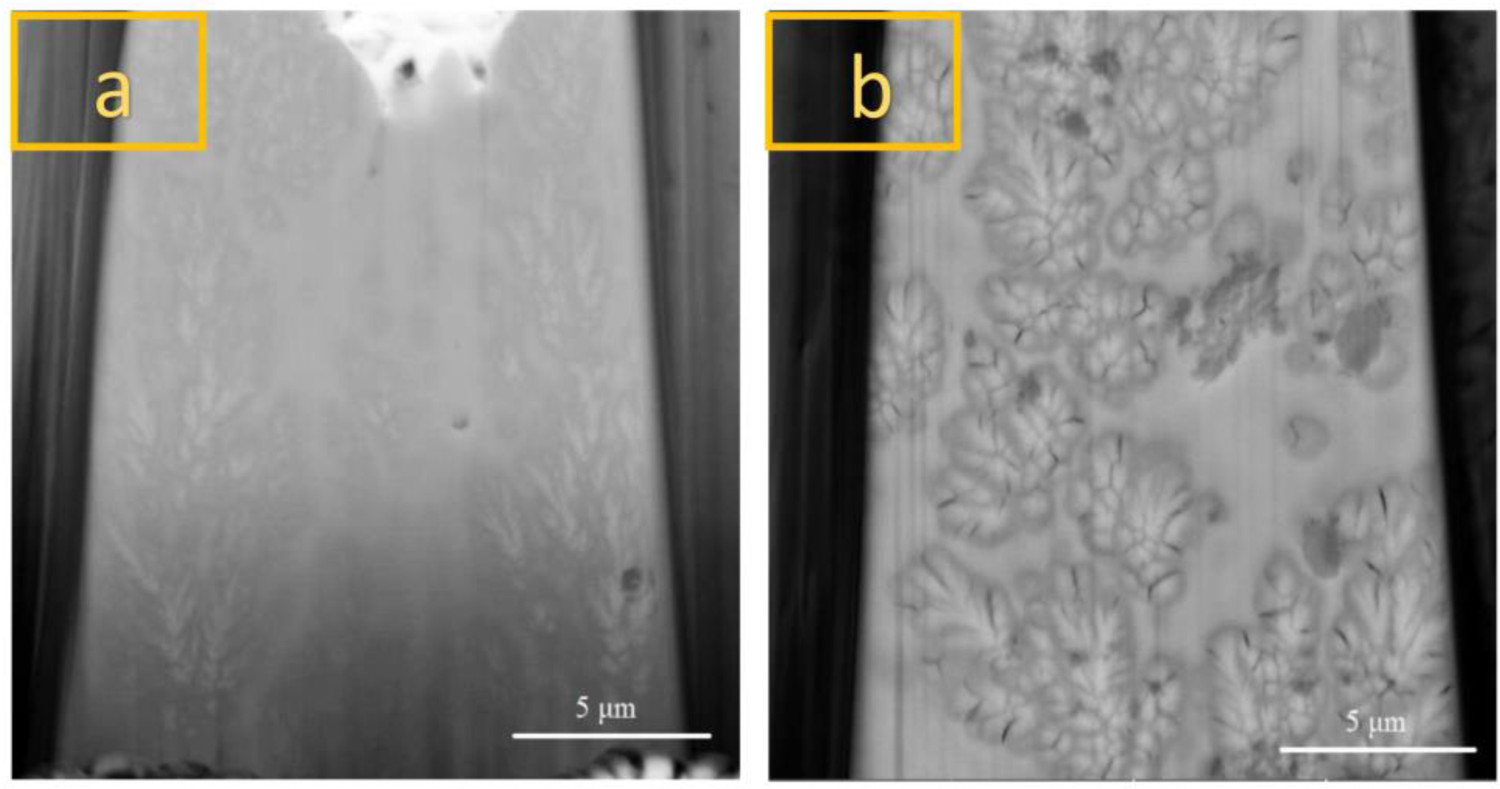
Non-continuous and non-compact cauliflowers formation in Ni–B coating implies that the redox reaction rate decreases as the time passes during deposition, this leads to the thickening of the diffusion layer and to delays in mass transfer. Based on the structure of the Ni–B–5CMC coating it seems that the mass transfer has happened continuously during the deposition. The reason for the formation of cracks in the specific direction of Ni–B sample is that uphill growth traps hydrogen bubbles between the asperities and, as a result, cracks are formed between the cauliflowers grains.
Corrosion behaviour
Corrosion characteristics of the coatings in 0.1M NaCl solution.
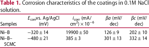
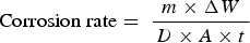
The corrosion rate of the specimens in mpy was calculated based on Equation 1 [33].
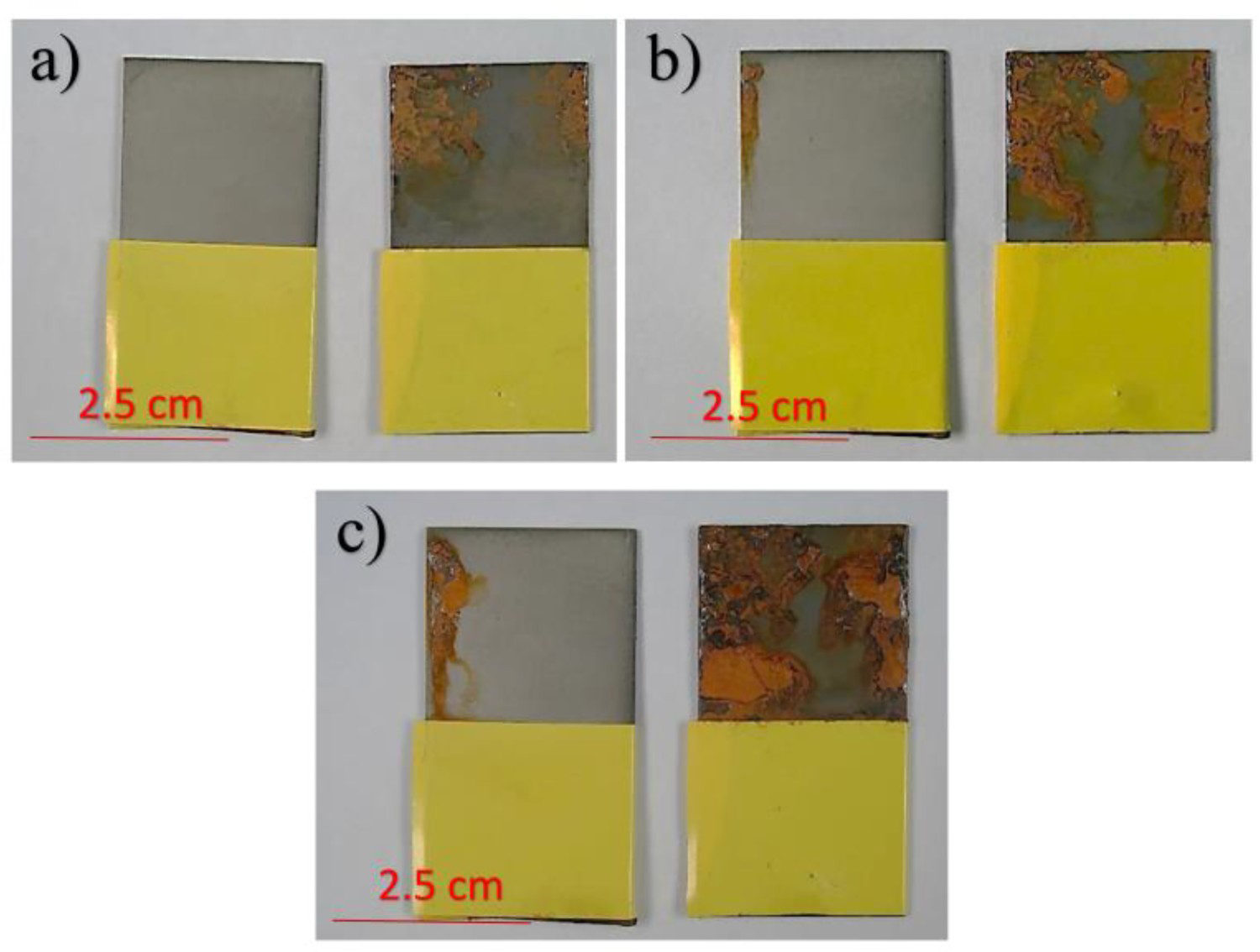
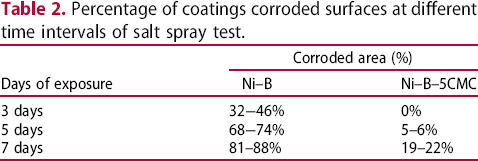
The aspect of corroded surfaces after 3, 5, and 7 days of salt spray exposure is shown in Figures 7 and 8 and the percentage of corroded surfaces is shown in Table 2. Based on the results a significant increase in corrosion protection is obtained for the sample having CTAB surfactant. The colour of the Ni–B corroded surface is darker than that of the Ni–B–5CMC sample, probably due to the formation of the Ni2O3 Nickel(III) oxide (which is sometimes referred to as black nickel oxide).
Potentiodynamic polarization curves of the coatings in 0.1M NaCl solution. Surface aspect of (left) electroless Ni–B–5CMC and (right) electroless Ni–B coatings after (a) 3 days, (b) 5 days, and (b) 7 days of salts spray. Percentage of coatings corroded surfaces at different time intervals of salt spray test.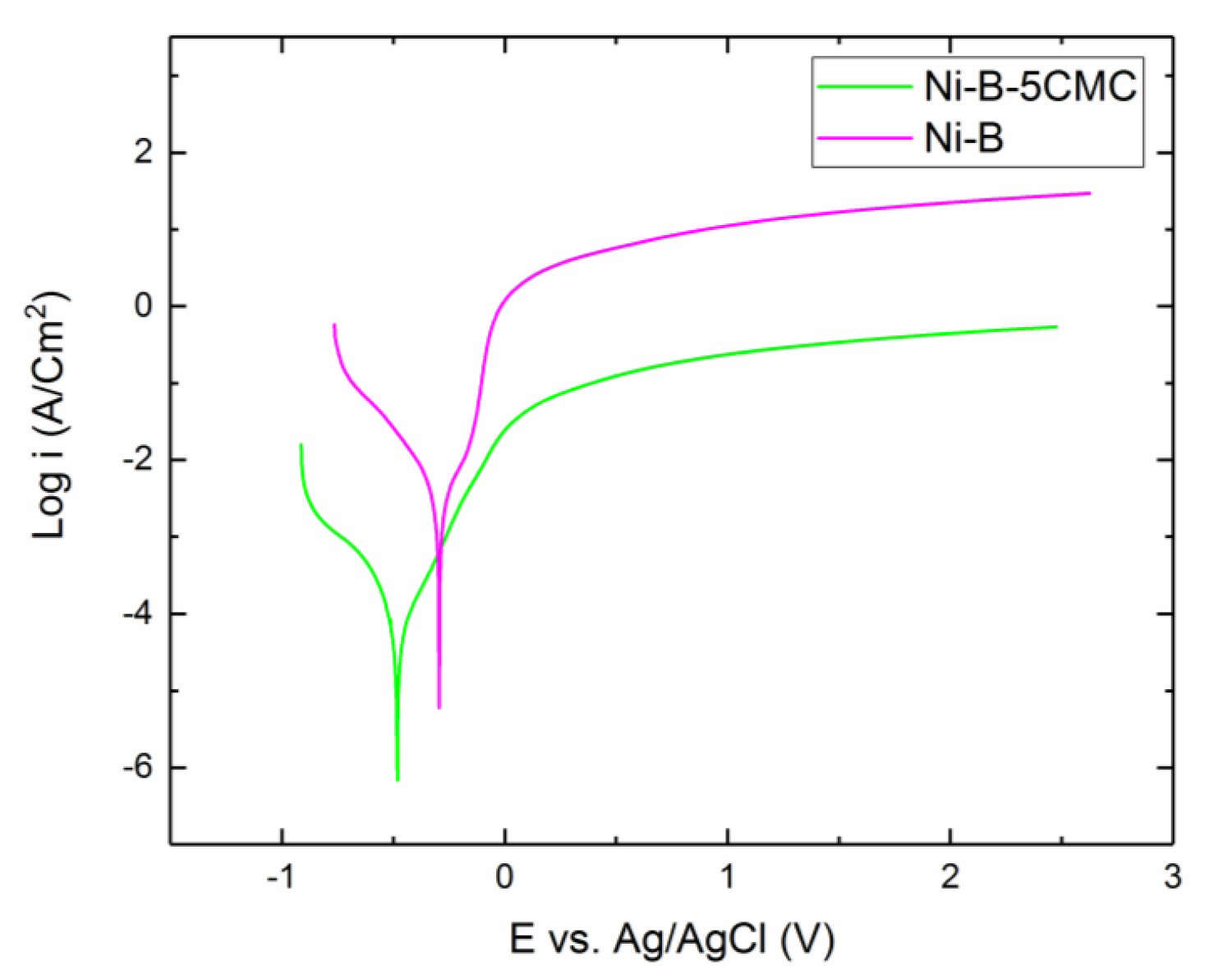
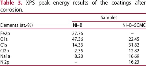
The corroded surface of the coatings after 7 days of salt spray exposure was analysed by XPS. The obtained XPS spectra (Figure 9 and Table 3) showed the presence of O and Ni at the surface of Ni–B–5CMC and of O and Fe at the surface of Ni–B samples. The Fe 2p spectra in Ni–B samples indicates breakdown of the protective passive layer and substrate exposure. No evidence of boron was observed in the XPS results. This might be due to the vacancy formation, Kirkendall effect happens and due to the differential transport rates of nickel and boron elements to the interface, higher selective dissolution of fast diffusing elements (boron) occurs.
XPS survey spectrum of the (a) Ni–B, (b) Ni–B–5CMC coatings after 7 days of salt spray exposure. XPS peak energy results of the coatings after corrosion.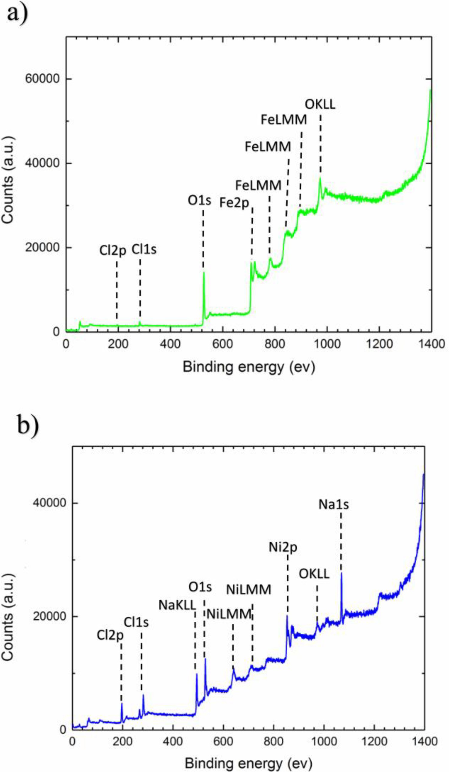
At the beginning of the corrosion, chloride ions preferentially absorb around micro-pits in Ni–B samples. This leads to non-homogeneous Cl−absorption and stronger dissolution of nickel and boron in these areas compared to other areas. On the other hand, the speed of passive layer formation depends on the dissolution rate of atoms. Therefore, the passive layer forms more rapidly (higher growth rate) in the micro-pits than other areas which results in passive layer breakdown (Figure 10(a)) due to stress accumulation. On the contrary, the absence of micro-pits and defects leads to homogeneous corrosive attack and formation of a passive layer with a constant growth rate all over the surface in Ni–B–5CMC samples (Figure 10(b)) that improve the corrosion resistance of the coating.
Schematic of the chemical reactions that occur during the corrosion process and its progress for (a) Ni–B, and (b) Ni–B–5CMC coatings.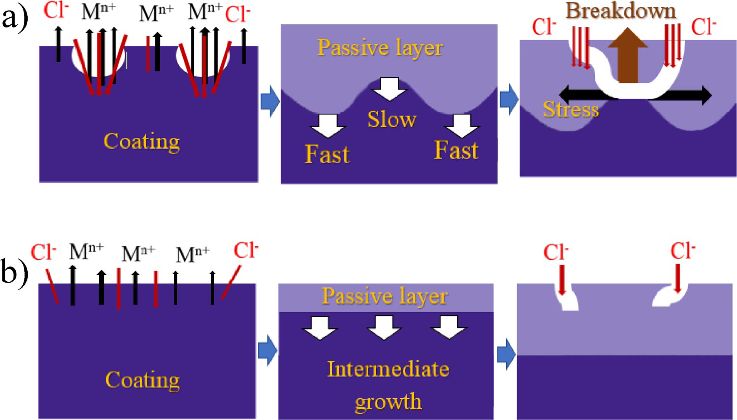
Scratch test
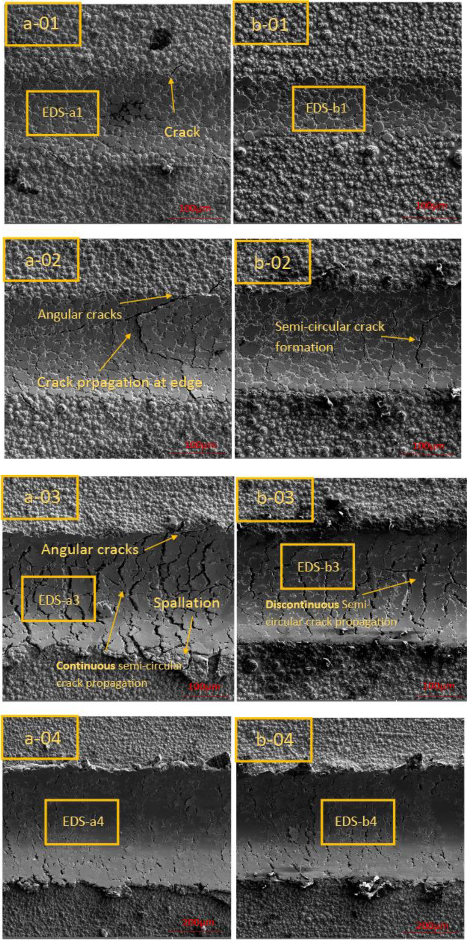
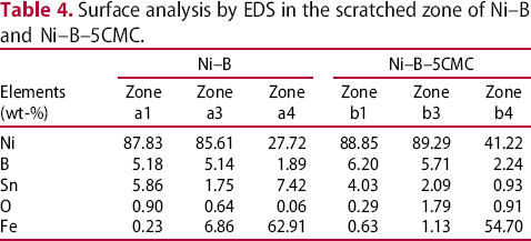
Figure 11 shows the scratched surfaces of the coatings. SEM and EDS analysis was performed on marked areas of the scratch surfaces (shown in Figure 11) to understand the adhesion behaviour of the coating. At the beginning of scratch test, the failure mechanism is local collapsing of material (Figure 12(a-01 and b-01)). No evidence of cracks, chipping and spalling was observed for the Ni–B–5CMC sample. However, a few longitudinal cracks on the edge of the scratch trace were observed in the Ni–B sample. As the load increases, angular cracks and semi-circular cracks are formed in both samples (Figure 12(a-02 and 12b-02)). These cracks can propagate more easily in Ni–B coating compared to Ni–B–5CMC coating.
Optical microscopic image of the scratched surfaces with the marked area for SEM and EDS analysis, up (Ni–B) and down (Ni–B–5CMC). SEM micrographs of scratch 1 surfaces of the (a-01) Ni–B, (b-01) Ni–B–5CMC, scratch 2 surfaces of the (a-02) Ni–B, (b-02) Ni–B–5CMCscratch 3 surfaces of the (a-03) Ni–B, (b-03) Ni–B–5CMCscratch 4 surfaces of the (a-04) Ni–B, (b-04) Ni–B–5CMC.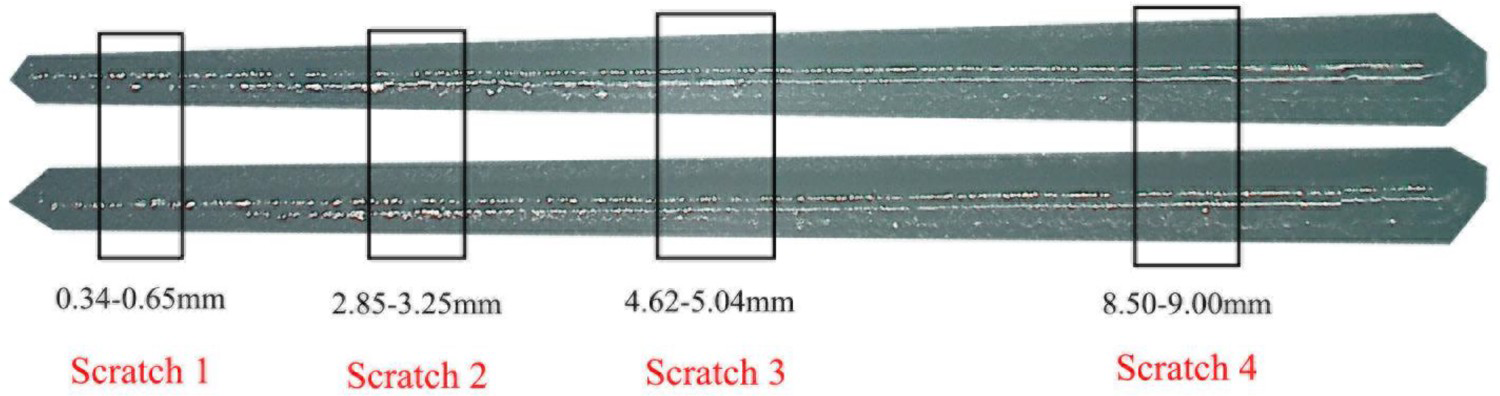
Surface analysis by EDS in the scratched zone of Ni–B and Ni–B–5CMC.
Conclusions
In this study, electroless Ni–B coatings were deposited on ST 37-DIN 17100 mild steel samples using CTAB surfactant at different concentrations ranging from 0.4 to 8 mM. Major results are as follows:
Increasing the surfactant concentration up to 2 mM (5CMC) promotes timely ions supplement at the substrate surface by decreasing the diffusion layer thickness which enhances the deposition rate. Presence of the surfactant eliminates the formation of pits at the surface and defects at the interface of the Ni–B coating. The potentiodynamic polarization results imply that adding CTAB surfactant into the electroless bath decreases the corrosion current density from 19,952 to 395 mA/cm2. More plastic deformation and higher continuous crack propagation were observed on Ni–B compared to Ni–B–5CMC coatings.
Adding CTAB surfactant provided better performance than electroless plating without surfactant and this new coating could be the candidate for a protective Ni–B coating in terms of corrosion resistance, wear, and mechanical properties.
Footnotes
Acknowledgements
The authors also want to thank to Mr Yoann Paintat Belgium Materia Nova Research Centre for the SEM analysis.