
Abstract
Influence of the concentration (0–1×10⁻³M) of Mo(IV) compounds on the electroless deposition of Co–Mo–P alloy from alkaline citrate bath was investigated. The changes of the plating potential, mass of the deposits and hydrogen evolution as well as composition and morphology of the deposits with the concentration of additives were determined. Similar behaviour was observed for all compounds. Increase in the
 concentration in the bath was accompanied by inhibition of Co–Mo–P deposition and only traces of deposits were obtained at 1×10⁻³M Mo(VI). Molybdenum content in the deposits was low and oxygen was detected in the layers produced at 5×10⁻⁴ and 1×10⁻³M Mo(VI). Such changes corresponded to a gradual evolution of the morphology of the deposits from needle to fine grained structure, but Na2MoO4 produced deposits of the best quality. Adsorption of
 ions at the metal/electrolyte interface was proposed as responsible for phenomena observed in the Co–Mo–P system.
Introduction
Cobalt–phosphorus thin films are interesting particularly with regard to their magnetic properties 1 1,2 as well as a barrier metallisation for copper in ultralarge scale integration. 3 3,4 The presence of molybdenum in the deposits improves their properties as barriers against copper diffusion into silicon substrate and as an oxidation protection layer.5 – 7 Increased corrosion resistance of Co–Mo–P alloys was also reported. 8 8,9 Cobalt–molybdenum–phosphorus alloys are usually produced by electrodeposition.7 – 10 It is known as an induced codeposition process, since molybdenum cannot be deposited by itself from aqueous solutions and the only possibility is codeposition with the iron group metals.11
Deposition of metals and alloys without external current source shows some advantages in comparison to the electrolytic process. It mainly includes formation of thin metallic layers with the uniform thickness and the homogeneous composition on a large number of conducting and non-conducting substrates with irregular profiles. No special instrumentation is also required. Electroless deposition of molybdenum containing layers has been not studied widely. Majority of available data refer to the electroless deposition of Ni–Mo–P alloys from alkaline citrate solutions.12
–
15 It was found that the molybdenum content in the nickel alloys increased (to a maximum value of 10–15 at-%) with increasing sodium molybdate concentration in the solution (to ∼0·02M). It was accompanied by a decrease in the phosphorus content and gradual inhibition of the process (electroless deposition of Ni–Mo–P stops at 0·02M
 in citrate solutions, but the course of the process can be improved by gluconate addition to the bath13). Depending on Na2MoO4 concentration either amorphous or crystalline Ni–Mo–P alloys were obtained.15
To date electroless deposition of cobalt with molybdenum has not been studied in details and no experimental data on this process are available. The only exception is a report of Shacham-Diamand et al.,5 who indicated a possibility of cobalt and molybdenum codeposition in the presence of sodium hypophosphite as a reductant. Therefore, it is of a special interest to find out some fundamental aspects of the process as well as to search for components of the bath to obtain deposits of a quality satisfied for applications in microelectronic devices. Hence, the aim of this work was to study the composition and morphology of Co–Mo–P alloys electrolessly deposited from alkaline citrate baths with various molybdenum compounds as a source of Mo(VI). These were molybdic acid, sodium and ammonium molybdates.
Experimental
Co–Mo–P films were deposited from solutions containing: 0·05M cobalt sulphate CoSO4.7H2O, 0·1M sodium hypophosphite NaH2PO2.H2O as a reductant, 0·1M trisodium citrate Na3C6H5O7.2H2O as a complexing agent, 0·2M boric acid H3BO3 as a buffer and 0·01M maleic acid C4H4O4 as a bath stabiliser. Three molybdenum compounds were used, including molybdic acid H2MoO4.H2O, sodium molybdate Na2MoO4.2H2O and ammonium molybdate (NH4)6Mo7O24.4H2O at a number of different concentrations [0–1×10⁻³M Mo(VI)]. The pH of the solutions was adjusted to 9·2 with NaOH. The plating bath (500 cm3) was agitated by a magnetic stirrer (250 rev min−1). Temperature of the plating system was maintained at 355 K. Copper plates (30 cm2) were used as substrates. Before each experiment, the substrates were etched with the HNO3 (1∶2) solution at room temperature for 60 s, and then washed with distilled water and acetone. The samples coated with the alloy films were washed in an ultrasonic washer with distilled water and then acetone. All substrates were weighed before and after deposition to determine the mass of the deposits. The electroless deposition on copper was induced by contacting the substrate for 5 min via an external conductor with an aluminium wire submerged in the bath. In the course of the plating, a potential of the sample versus saturated calomel electrode (SCE) was recorded and hydrogen in a gaseous burette was collected. Total plating time was 70 min. Morphology of as plated deposits was examined by means of a scanning electron microscope (Hitachi S 4700), while energy dispersive X-ray spectrometry (Noran) was used to analyse the elemental composition of the deposits. X-ray diffraction patterns of Co–P and Co–Mo–P samples were obtained using Cu Kα radiation (XPertPro Philips spectrometer).
Results and discussion
Three compounds were used as a source of Mo(VI) in the cobalt–citrate plating baths: molybdic acid, sodium or ammonium molybdate. All compounds can form various ionic species (
 ,
,
 ,
,
 and
and
 ) in aqueous solutions. Distribution of soluble molybdenum(VI) species depends on pH,13 but
 anion predominates in the baths at pH above 8, despite of the possibility of molybdate–citrate complex formation.16 On the other hand, the degree of the citrate protonation in alkaline solutions determines formation of cobalt–citrate complexes.17 It was calculated that under experimental conditions, citrate exists mainly as two ionic species H−1Cit4− and Cit3− forming two complexes with Co(II): CoH−1Cit2− (4·7×10−2M) and CoCit− (3·0×10−3M) corresponding to 94·1 and 5·9% of total Co(II) concentration in the bath respectively. Other cobalt species represent only negligible fractions in the electrolyte (6·1×10−7M Co2+, 9·4×10−9M CoHCit and 2·4×10−15M CoH2Cit+). It is not certain if cobalt–molybdate complexes can also exist in the bath by analogy with Ni(II) –Mo(VI) heteropolymolybdate ion.18
Co–P and Co–Mo–P films were deposited onto the copper substrate. Copper does not exert any catalytic effect on the oxidation of hypophosphite anion in the electroless process; hence an aluminium wire was used to induce cobalt deposition. Once cobalt nuclei were deposited, the reaction continued due to its self-catalytic nature. Figure 1 shows exemplary changes of the potential during plating. Independently on the bath composition, three characteristic stages were found:
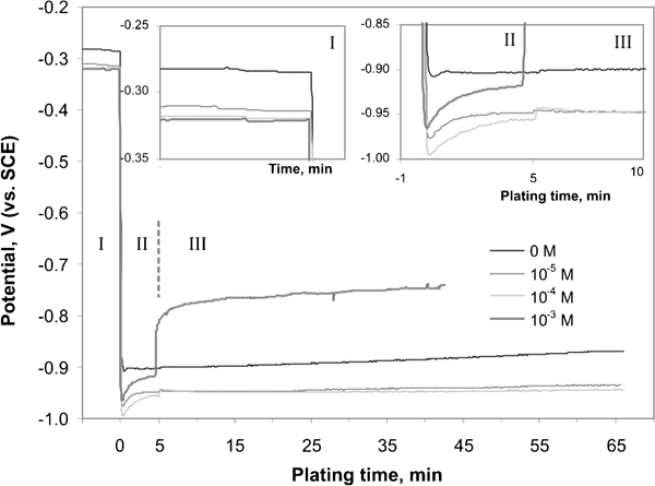
Changes of potential in presence of sodium molybdate of various concentrations
stationary state (Fig. 1, inset). Potential of the substrate immersed in the solution was dependent on the bath composition even though any redox reactions were not taking place on the copper surface. The potential of approximately −0·28 V(SCE) was maintained in the cobalt solution, but it decreased by ∼0·04 V in the presence of molybdenum compounds. It may suggest that molybdate anions can adsorb on the substrate changing the structure of the double layer at the copper surface.
initiation of the process (Fig. 1, inset). A sudden decrease in the potential to about −0·95±0·05 V(SCE) was observed due to connection of the copper substrate with an aluminium wire. The potential stabilised at the constant value in the cobalt bath, but it increased by 0·03–0·07 V from the initial value (lower than that for the Co–P system) during the initiation step in the presence of molybdate ions. It shows that nucleation of metallic cobalt occurs easily in the galvanic cell, whereas molybdate anions show an inhibiting effect on this stage.
right catalytic deposition. The mixed potential stabilised at constant values dependent on the molybdate anions concentration. It was observed that autocatalytic cobalt deposition occurred at the potential of approximately −0·90 V the same as in the initiation stage, while in the presence of molybdate ions the potential was maintained at various levels. For Mo(VI) concentrations of 5×10⁻⁴ and 1×10⁻³M, jumps of the potential were observed after Cu–Al disconnection. However, values reached later were different from that observed in the stage (i). It shows that the composition of the substrate surface changed during the initiation step.
Figure 2 shows the influence of
 concentration on the plating (mixed) potential, mass of the deposits and volume of hydrogen evolved during the process. Deposition of Co–P films occurred at the constant potential of −0·90 V. The mixed potential for Mo(VI) concentrations up to 1×10⁻⁴M was by 0·05 V lower than that for the Co–P system, but it shifted gradually towards more positive values upon further molybdate addition. Similar tendency was observed by Lu and Zangari13 during Ni–Mo–P electroless deposition. Such characteristic curve shows usually a plateau corresponding to a critical molybdate concentration, where the process stops completely and the mixed potential remains almost constant for
 concentrations above this critical value.
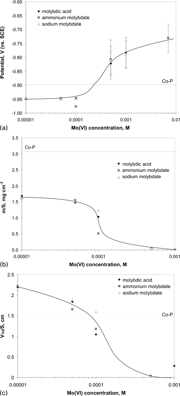
Influence of concentration of Mo(VI) species on a plating (mixed) potential, b mass of deposits and c hydrogen volume
The changes in the mixed potential corresponded to the hindering of the electroless process. In the presence of 1×10⁻⁵–5×10⁻⁵M Mo(VI) mass of the deposits was twice smaller than that for Co–P layer and it decreased with increased molybdate concentration. For 1×10⁻³M Mo(VI) in the bath only traces of the deposits were obtained. It corresponded to the mixed potential of approximately −0·75 V(SCE), which seems to be the critical potential for the Co–Mo–P system. Measurement of the plating potential during deposition was found useful for controlling the process due to direct monitoring electroless deposition without necessity of the removal of the sample from the bath.
Figure 3 shows the manner by which the mass of the deposits varied with the plating potential. The potential was a linear function of the logarithm of the deposit mass. This behaviour is similar to Tafel-like plots. It indicates certain inhibition of the charge transfer step of the electrochemical process as a result of the tendency of molybdate anions to adsorption on the catalytic cobalt surface. It is interesting to note that the experimental point representing the bath with no molybdenum addition showed a deviation from the linear plot. It seems rather obvious, since participation of cobalt ions in the total process differed from that in the presence of molybdenum species probably due to inhibiting properties of the latter.
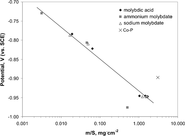
Tafel-like plot
The electroless deposition was accompanied by hydrogen evolution. The volume of the gas was monitored during plating (Fig. 2c). For all baths the amount of the gas was affected mainly by the Mo(VI) concentration and no considerable differences in the hydrogen evolution in the presence of various molybdenum compounds were found. Decrease in the hydrogen evolution in the presence of the additives was strictly related to the inhibition of the deposition process under molybdate addition.
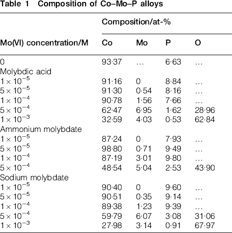
The electroless deposition of cobalt with molybdenum by hypophosphite was also accompanied by incorporation of phosphorus. Table 1 shows composition of the deposits produced in various baths. It was found that type of the molybdenum compound does not exert any significant influence on the composition of the deposits, but there are some changes in the actual contents of the individual elements at different concentrations of Mo(VI) species. Molybdenum percentage in the alloys was low (only a few atomic per cent) and it increased with molybdate addition to the electrolyte. The highest values (3–7 at-%) were found in the layers produced at the two highest Mo(VI) concentrations, but it was accompanied by the presence of large amounts of oxygen. It seems that rather adsorbed molybdate species or molybdenum oxide than elemental molybdenum was present in such deposits. It corresponded to very low mass of the deposits confirming inhibiting effect of the anions. An interesting effect was also observed for 1×10⁻⁵M Mo(VI) in solution. In this case molybdenum was not detected in the deposits, whereas increased phosphorus percentage in comparison to Co–P alloy was found.
Composition of Co–Mo–P alloys
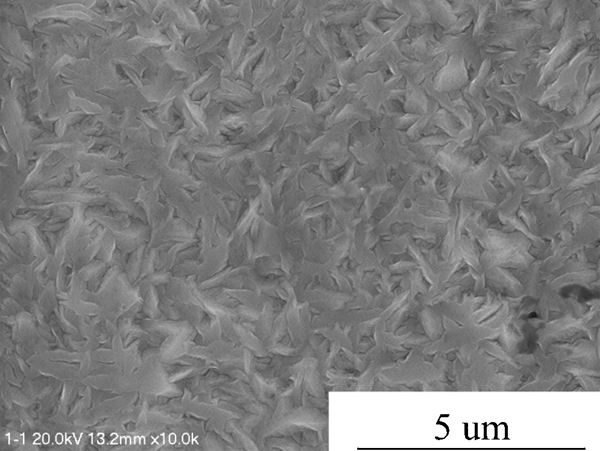
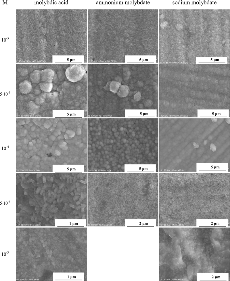
All Co–P and Co–Mo–P deposits were compact and characterised by smooth gray mat surfaces. The surface topography of as plated deposits was dependent mainly on the concentration of the molybdenum species in the baths and no serious effect of the compound type was observed. It seems understandable since
 anion predominates in the baths at pH above 8 (Ref. 13) and all compounds dissociate in the alkaline solution. The Co–P layer (Fig. 4) consisted of star-like grain characteristics for hexagonal cobalt and cobalt rich deposits.16,19
–
21 This morphology evolved gradually via needle and nodular to the fine grained structure with increased Mo(VI) concentration (Fig. 5). At 1×10⁻³M Mo(VI) deposits seemed to be flocculent at the grain boundaries. It suggests incorporation of non-metallic occlusions. Similar changes were observed for all molybdenum compounds, but deposits were more compact and characterised with smaller grains in the presence of sodium molybdate. Significant changes in the surface morphology confirm the adsorption of molybdate anions. It is known
2
2,11 that increase in the electrode overpotential caused by adsorbed species leads to the inhibition of the grain growth. It enhances nucleation stage and deposition of the metal as a fine grained layer. This phenomenon was rather well illustrated in this study, since the plating potential changed as the concentration of molybdenum additive increased and the structure of the deposits evolved from ramified coarse grains with clearly visible grain boundaries to fine grained deposits.
anion predominates in the baths at pH above 8 (Ref. 13) and all compounds dissociate in the alkaline solution. The Co–P layer (Fig. 4) consisted of star-like grain characteristics for hexagonal cobalt and cobalt rich deposits.16,19
–
21 This morphology evolved gradually via needle and nodular to the fine grained structure with increased Mo(VI) concentration (Fig. 5). At 1×10⁻³M Mo(VI) deposits seemed to be flocculent at the grain boundaries. It suggests incorporation of non-metallic occlusions. Similar changes were observed for all molybdenum compounds, but deposits were more compact and characterised with smaller grains in the presence of sodium molybdate. Significant changes in the surface morphology confirm the adsorption of molybdate anions. It is known
2
2,11 that increase in the electrode overpotential caused by adsorbed species leads to the inhibition of the grain growth. It enhances nucleation stage and deposition of the metal as a fine grained layer. This phenomenon was rather well illustrated in this study, since the plating potential changed as the concentration of molybdenum additive increased and the structure of the deposits evolved from ramified coarse grains with clearly visible grain boundaries to fine grained deposits.
Morphology of as plated Co–P deposit
Effect of concentration of Mo(VI) species on morphology of as plated Co–Mo–P deposits
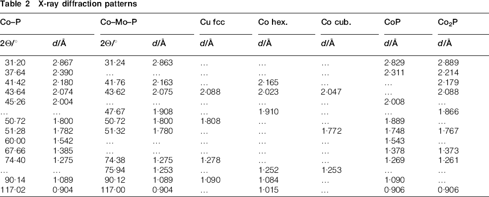
Figure 6 shows diffraction patterns of crystalline Co–P and Co–Mo–P deposits obtained at various concentrations of ammonium molybdate as examples. Standards used for identification of the individual peaks are summarised in Table 2. Cobalt was the main component of the deposits, but some peaks could be ascribed to metallic copper used as the substrate. The presence of both CoP and/or Co2P phases cannot be excluded, since diffraction peaks for both phases overlap. No peaks of pure molybdenum were detected in the deposits, since it does not form a separate metallic phase in the Co–Mo alloys with low molybdenum contents.22 However, the presence of that element could induce formation of face centered cubic cobalt phase or Co–Mo solid solution phase22 due to molybdenum (cubic structure) incorporation to the Co–Mo–P deposit. It is worth to note that electrodeposited Co–Mo alloys containing low molybdenum percentages (<10%) characterised with the hexagonal structure with no separate molybdenum phase.19
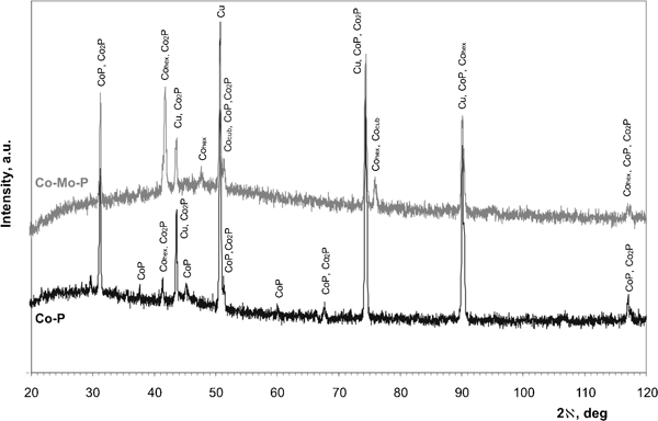
X-ray diffraction patterns of Co–6·63P and Co–3·01Mo–9·80P (at-%) deposits
X-ray diffraction patterns
An overall reaction of the electroless cobalt deposition in the alkaline solution using hypophosphite as the reductant can be written as follows


 ions in the electroless process takes place probably through a few steps; however, there is not any convincing experimental evidence on this subject.13 For electrolytic deposition of Co–Mo–P alloys a following sequence of the stages was proposed: an electrochemical reduction of molybdate anions to molybdenum(IV) oxide and then a chemical reduction of the oxide to metal.7 More detailed studies on electrodeposition of cobalt with molybdenum from citrate baths were presented by Gomez et al.,19
–
21 who considered formation of an adsorbed [MoO2–CoCit−] complex as intermediate species in the molybdate reduction.
ions in the electroless process takes place probably through a few steps; however, there is not any convincing experimental evidence on this subject.13 For electrolytic deposition of Co–Mo–P alloys a following sequence of the stages was proposed: an electrochemical reduction of molybdate anions to molybdenum(IV) oxide and then a chemical reduction of the oxide to metal.7 More detailed studies on electrodeposition of cobalt with molybdenum from citrate baths were presented by Gomez et al.,19
–
21 who considered formation of an adsorbed [MoO2–CoCit−] complex as intermediate species in the molybdate reduction.
 is known also as a corrosion inhibitor.
23
23,24 The effectiveness of molybdate anions as anodic or cathodic corrosion inhibitor was explained by both adsorption theory23 or reduction of soluble Mo(VI) compound to insoluble Mo(VI) state (MoO2),24 but the role of
is known also as a corrosion inhibitor.
23
23,24 The effectiveness of molybdate anions as anodic or cathodic corrosion inhibitor was explained by both adsorption theory23 or reduction of soluble Mo(VI) compound to insoluble Mo(VI) state (MoO2),24 but the role of
 is still not understood. The presence of oxygen in Co–Mo–P layers electrolessly deposited at higher Mo(VI) concentrations shows that reduction of
 by hypophosphite can run through formation of molybdenum oxide containing intermediate species. Such precipitates do not exert any catalytic effect on the oxidation of hypophosphite anion. They prevent the contact of the reductant molecule with a catalytic cobalt surface and act as an inhibitor of metal deposition. It is interesting that at Co/Mo ratio in the deposits containing oxygen is practically constant [Co/Mo is (9±1)∶1]. It makes probable formation of an adsorbed cobalt ions molybdenum oxide complex as intermediate species as it was proposed by Gomez et al.
20
20,21 for electrodeposition process. However, a detailed study on the mechanism of the process is needed.
by hypophosphite can run through formation of molybdenum oxide containing intermediate species. Such precipitates do not exert any catalytic effect on the oxidation of hypophosphite anion. They prevent the contact of the reductant molecule with a catalytic cobalt surface and act as an inhibitor of metal deposition. It is interesting that at Co/Mo ratio in the deposits containing oxygen is practically constant [Co/Mo is (9±1)∶1]. It makes probable formation of an adsorbed cobalt ions molybdenum oxide complex as intermediate species as it was proposed by Gomez et al.
20
20,21 for electrodeposition process. However, a detailed study on the mechanism of the process is needed.
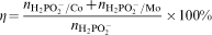
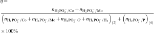
It can be assumed that efficiency of the electroless plating η is determined by the ratio of the amount of the reductant consumed for reduction of metallic ions in the reactions (3) and (6) to the total amount of hypophosphite
 consumed in the process25
 ions are utilised in the anodic reaction (2) to course the cathodic reactions (3)–(6); they are also substrates in the reaction (4). Hence
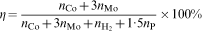
 and nP are the amounts of the moles of cobalt, molybdenum, hydrogen and phosphorus produced in the electroless process respectively. In each experiment, percentages of cobalt, phosphorus and hydrogen in the deposits were determined and counted over the number of moles and then the efficiency of the process was calculated. It was estimated that only 20% of the reductant was consumed for Co–P deposition, whereas in the presence of molybdate anions efficiency reached 10–15%. The highest values (25–45%) were obtained in the baths with 5×10⁻⁴ and 1×10⁻³M of the additive; however, such values are seriously overestimated due to the low mass of the deposits and no certainty on the molybdenum state (i.e. metal or oxide) in the deposits. The literature does not offer any detailed information on the efficiency of the electroless cobalt plating, but calculations confirm low efficiency of the Co–P deposition.25
Results obtained in this study show that behaviour of the Co–Mo–P electroless plating system was the same regardless the type of the molybdenum compound (acid and salt) used. In all cases inhibition of the process appears to be associated with adsorption of
 ions at the metal/solution interface. Molybdate ions can block the sites for hypophosphite oxidation and metal ions reduction, lowering the deposition rate or completely stopping the process. In the electroless plating systems the adsorption hypothesis seems to be the most reasonable; however, more detailed studies are necessary.
Conclusions
The influence of the concentration of molybdic acid, sodium molybdate and ammonium molybdate in the bath on the electroless deposition of Co–Mo–P was investigated. Similar behaviour of the plating potential, mass of deposits and hydrogen evolution as well as composition and morphology of the deposits for all molybdenum compounds was observed. Increase in the Mo(VI) concentration was accompanied by a decrease in the amount of deposited Co–Mo–P films with a stopping of the process at 1×10⁻³M Mo(VI). Molybdenum content in the deposits was low, but oxygen was also detected in the layers produced at 5×10⁻⁴ and 1×10⁻³M Mo(VI). Such changes corresponded to a gradual evolution of the morphology of the deposits from needle via nodular to the fine grained structure. The most compact and even deposits were deposited in the presence of Na2MoO4 at concentrations up to 1×10⁻⁴M. It was proposed that adsorption of
 ions at the metal/electrolyte interface was responsible for phenomena observed in the Co–Mo–P plating system. Molybdenum content in the Co–Mo–P alloys was much smaller and the electroless deposition stopped at a lower Mo(VI) concentration than that for Ni–Mo–P alloys.
Footnotes
Acknowledgements
This research work has been supported by the Polish Ministry of Science and Higher Education under project no. 11·11·180·374.