
Abstract
Magnesium alloys have received increasing consideration as biodegradable implants owing to their high specific strength, excellent biocompatibility and non-toxicity but their biomedical applications are limited due to low corrosion resistance which can be improved by surface modification and alloying with suitable elements. Various surface modifications of Mg alloys by deposition of different coatings are used to prevent untimely dissolution. This study presents the corrosion behaviour of a thin ZnO coating deposited on a Mg–Zn–Zr alloy by electrophoretic deposition in the Ringer's solution at 37°C. It was found that the ZnO coating is compact, homogeneous and significantly enhanced its corrosion resistance according to electrochemical test. The polarisation test showed a two orders of magnitude lower current density than that of the bare alloy, while EIS study found a two orders of magnitude greater ZnO coating impedance increasing in bioactivity. The bare specimens showed the development of cracks on the surface whereas the ZnO coated alloy showed no signs of pitting.
Keywords
Introduction
The demand for Magnesium alloys is increasing tremendously in biomedical due to their high specific strength, excellent biocompatibility, non-toxicity and ideal Young's modulus (41–45 GPa). [1–3] The tensile and compressive properties of these alloys is significantly higher compared to the other materials used for bone implantation. Moreover, magnesium ions play a vital role in adequate functioning of the body, so as the implantation can partially cover the human's necessity for this element [4,5]. Still, its biomedical applications are limited due to low corrosion resistance and strength which can be enhanced by surface modification and alloying with suitable elements [6].
Ideally, a biomaterial will be absorbed by the body in wound healing process, removing the requirement of surgery for elimination of implant. Zinc (Zn) has emerged as an excellent candidate among the all-available resorbable metallic materials and has acceptable corrosion rate for healing tissues under physiological conditions [7,8]. But Zn confines its applicability in load bearing implants, due to lower mechanical strength. Therefore, Zn has been alloyed with magnesium as it has no negative impact on human body along with the improvement in mechanical properties [9]. Besides, corrosion resistance of magnesium alloy increases by the addition of Zn and also the in-vitro and in-vivo biocompatibility of Magnesium (Mg) metal. [10–12]
The surface modification of Mg alloy by coating can further lessen the corrosion activity in body fluid. Among all the types of coating, inert materials as ceramic coatings are best to improve the corrosion resistance in various mediums [13]. ZnO coating on Mg alloy was selected due to its excellent bacterial resistance, without affecting the pH of surrounding environment [14]. Zn is also found in human bone, and preferably increases the formation of proliferation of osteoblasts, mineralisation of extracellular matrix and biomimetic compounds [15,16]. It has been reported that Zn enhances the osseointegration and cytotoxicity at low and high concentrations respectively [17]. Therefore, Zn incorporated on implant surface may provide and promote osteogenic activity and antibacterial capabilities. The addition of Zr is widely used as a grain refiner in magnesium alloys and shows great in-vitro and in-vivo biocompatibility and osseointegration [18,19]. Therefore, as-extruded Mg–6Zn–0.5Zr alloy has been used in this study, which has higher yield stress [20,21] and better fatigue properties [22].
Several studies have already been carried out on various substrates for the deposition of biocompatible compounds using different techniques. Yet, time-dependent degradation behaviour analysis of ZnO coating on Mg alloy has not been discussed. The improvement in anticorrosive properties and bioactivity of Magnesium alloy by surface modification has been proposed in this work. Moreover, the overtime stability of ZnO coating on ZK60 alloy has been investigated in Ringer's solution by combining potentiodynamics studies (Tafel Plots), electrochemical impedance spectroscopy (EIS), X-ray diffraction (XRD) along with scanning electron microscopy (SEM) and energy dispersive X-ray (EDS) analysis.
Materials and methods
Synthesis of ZnO particles
Sodium hydroxide pallets and zinc nitrate hexahydrate were used as precursors in co-precipitation method to synthesise ZnO powder. Aqueous solution of 0.8M of NaOH and 0.1M of Zn(NO)3 were prepared with demineralised water at room temperature. The NaOH solution was injected drop-wise in the Zn(NO)3 suspension to avoid any inhomogeneity and non-stoichiometry [23]. The precipitates were rinsed three times with demineralised water after the solution was removed through filtration to remove byproducts. Finally, the precipitates were dried in oven at 60°C for 24 h.
Co-precipitation method was used as this method could yield a significant amount of synthesised powder at a reasonable cost. Besides, this reaction doesn't involve any foreign elements, and water is the only byproduct [24].
Measurement of particle dispersion stability by zeta potential
The stability of ZnO particles in suspension as a function of pH in order to determine the appropriate pH for the electrophoretic suspension for the EPD process was measured by Zetasizer Nano-series, Malvern Instrument has been shown in Figure 1.
Zeta potential at different pH values for ZnO suspension at room temperature.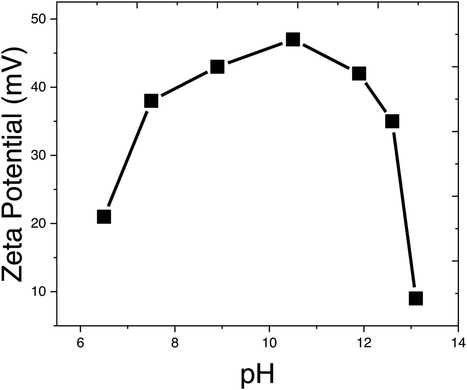
The absolute values of zeta potential define the strength of repulsive electrostatic forces between particles in colloidal suspension, which show the key property of agglomeration and strength between colloidal particles. It has been reported in literature that the absolute zeta potential values greater than or equal to ± 30 mV indicate steady dispersions. The basic-pH of the solution was adjusted using magnesium nitrate based on the zeta potential measurements, in order to achieve a stable suspension for ZnO deposition on ZK60 alloy samples, and pH levels were monitored by pH metre.
Electrophoretic deposition
Electrophoretic dispersion was prepared by dispersing 0.6 g of ZnO powder in 350 mL of propanol. The pH of solution was adjusted to 10.5 by adding 0.04 g Mg(NO3)2 as anionic surfactant and allowing the solution to settle for one hour. Glycerin was added in suspension, for the mechanical bonding to the substrate.
316 Stainless steel and ZK60 were used as anode and cathode respectively, with electrodes 3.0 cm apart and a using a DC power source was used to apply 0.8 KV for 1 min at room temperature. The coated samples were left at room temperature for a duration of 2 h, to complete the ageing process. The deposited ZnO coating was sintered at 330°C for 2 h at a heating rate of 5°C/min to densify and improve adhesion. ZnO coated surface was characterised by X-ray diffraction (XRD), Fourier Transformed Infrared Spectroscopy (FT-IR) and scanning electron microscope (SEM) coupled with energy dispersive X-ray spectroscopy (EDS).
In vitro corrosion test
Tafel Plots and electrochemical impedance spectroscopy techniques were used to conduct electrochemical studies on the bare ZK60 alloy and ZnO coated ZK60 alloy in Ringer's solution at 37°C by using three-electrode cell on workstation Gamry Reference 600. The electrochemical measurements were conducted twice to ensure their validity and open circuit potential (OCP) measurements were carried over 48 h. Tafel Plots scan was done from −0.25 V to 0.5 V at a scan rate of 1 mV/s. Electrochemical impedance spectroscopy (EIS) was performed at the frequency range between 100 kHz and 10 mHz with a root mean square sinusoidal potential perturbation signal of 10 mV. The interpretation of EIS data has been assisted through equivalent circuit models have been proposed and fitted on Nyquist and Bode plots, by employing passive electrical engineering and physics circuit components.
Characterisation techniques
The particle size of the ZnO powder was measured by Zetasizer Nano-series (Malvern Instrument). 20 ml of ethylene glycol was mixed with 0.010 mg of ZnO powder in a disposable cuvette, followed by sonication for 10 min, and the size of the powder was then determined at room temperature.
The crystal structure of powder was determined by XRD with Cu Ka radiation (⅄ = 0.154 nm) with a scan rate of 1/min, the incident angel was 0.5 and the XRD spectra were recorded against 2θ range of 10° to 80°. The chemical bonding and functional group present in the synthesised ZnO powders and the coated Mg alloy surface were identified by FT-IR. The FTIR with a resolution of spectra of 1 cm−1 was used to record FTIR spectra of ZnO powder (as pellets in KBr) and ZnO coated Mg alloy in attenuated total reflection (ATR) mode (diamond crystal) in the range of 4000-400 cm−1. The surface morphologies of the ZnO powder and coated alloy surface were investigated by SEM and the weight percentage of ZnO was determined with EDS.
The contact angle was determined by using Contact Angle plugin in ImageJ software, at the point where the chord connecting the droplet and the circle's circumference meet at the sample surface. Two at the left and right contact angles and three at the droplet border were chosen from a total of five points on the contour line of the water droplet image. The droplet contour line was then fitted with an ellipse. The left and right contact angles were estimated.
Results and discussion
Characterisation of ZnO powder and ZnO deposited Mg alloy surfaces
The particle-size distribution of the synthetic ZnO powders as determined by laser particle analyzer is shown in Figure 2. The results demonstrate that the synthesised powders have a mean particle size of 0.77 μm and that the particle sizes range from 0.1 to 1.0 m.
Particle-size distribution curve of synthesised ZnO.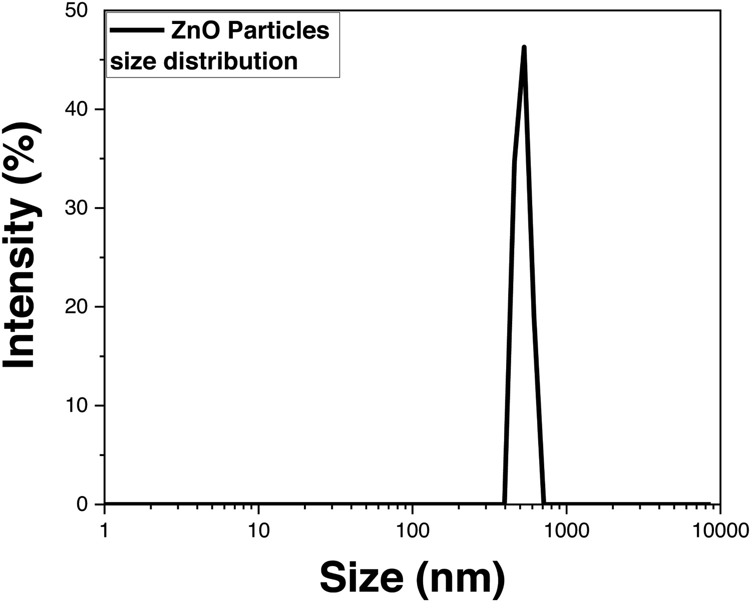
XRD (Rigaku D/MAX-3A/1981) was used to identify the crystal structure of synthesised ZnO powder and ZnO film on Mg substrate has been shown in Figure 3. The three most intense peaks at (100), (002), (101) planes reflection can be indexed to the known hexagonal structure of ZnO (JCPDS, Card No. 65-3411) [25]. The narrow width and strong intensity of diffraction pattern shows that the ZnO particles formed were highly crystalline. No diffraction peak has been identified from any other species, indicating that the synthesised powder was pure ZnO. It has been noticed that there is a slight shift in XRD peaks which may be due to residual stresses which arises from non-alignment of sample during experiment.
The X-ray diffraction spectra of the synthesised powders and coated surface of ZK60 alloy.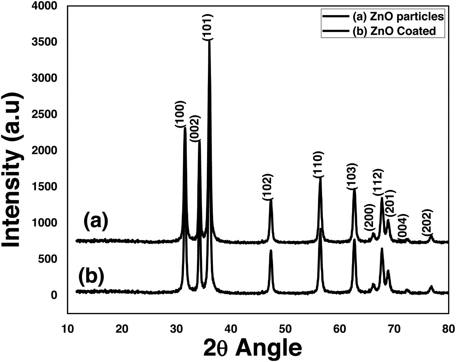
FTIR (Nicolet iS50) spectra of ZnO powder and ZnO coated on Mg alloy has been shown in Figure 4. Five sharp peaks can be seen in the Spectral range between 1000–1100 cm−1. Metal oxides usually indicate absorption bands below 1000 cm−1 as result of interatomic vibrations [26]. The spectrum shows a board peak at 3412.6 cm−1 and a small peak at 2046.4 cm−1 indicating the presence of OH− stretching and bending modes related to the adsorbed water. The peaks at 620.2, 1370.0 cm−1 and around 840.0 cm−1 corresponds ZnO stretching bonds. These frequencies for metal oxides match with the earlier reported in literature [27]. The FTIR of synthesised ZnO powder and the one coated on ZK60alloy shows that both spectra are almost similar except for a minor peak change showing that the interatomic bonding remains intact during the coating process.
The FT-IR plots of synthesised (a) bare ZnO particles (b) ZnO coated ZK60 alloy.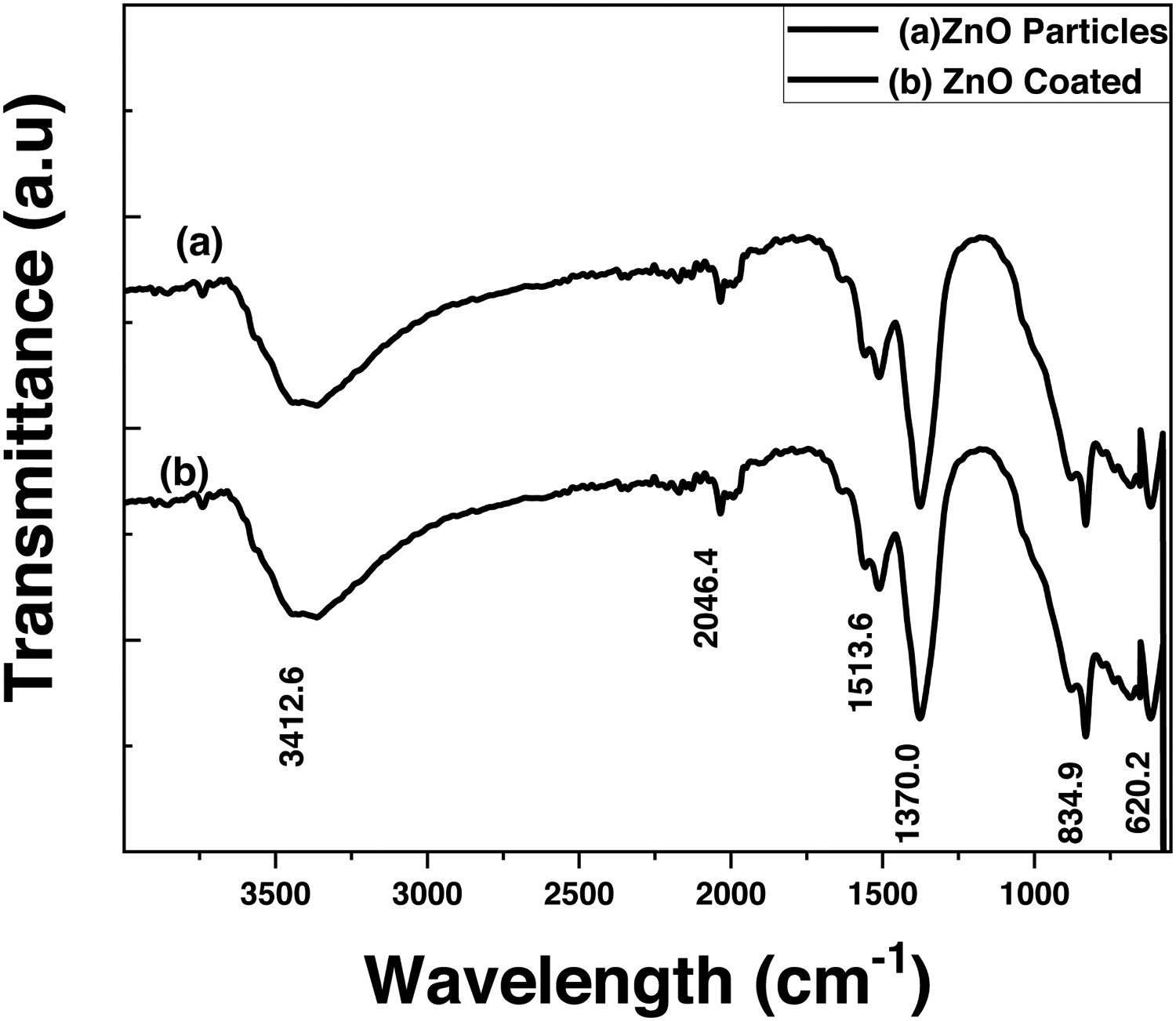
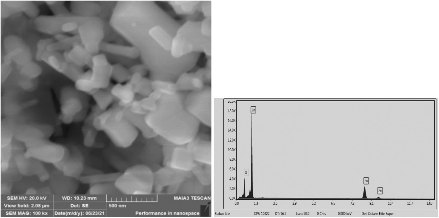
The micrograph in Figure 5 clearly shows the SEM image of synthesised ZnO powders. The image reveals agglomerated particles in long-rod shape, length of the rod is about 3–5 µm and the width is between 300 and 800 nm, and a typical nano-structure is formed; along with strong peaks of Zn and O in the EDX data plot. ZnO is a polar crystal that is rich in Zn and O with positive and negatively polar planes and its rods are randomly distributed in powdered sample in different orientations attributed as crystal habit. [28]. It has been reported that these rods agglomerates once they achieve a stable size, then randomly collide with smaller particles to form nuclei, leading to self-assembly, that may take place randomly or extremely oriented procedure [29].
The scanning electron micrograph image of the ZnO powder along with energy dispersive X-ray (EDX) analysis. The scanning electron micrograph image of the ZnO coated ZK60 alloy surface coupled with energy dispersive X-ray (EDX) analysis of the coating.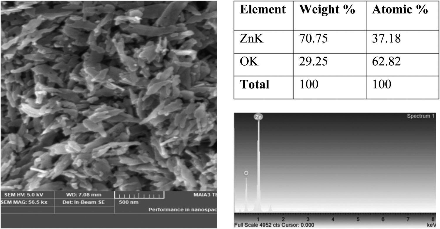
FESEM (TESCAN, model MAIA-3) equipped with EDX detector (Octane Elite) and accelerating voltage of 20KV, was used to determine the image of coated ZnO sample is shown in Figure 6. The morphology of the ZnO coated alloy significantly changes during the sintering process, giving the appearance of short, thick-rod shape particles and widening the average particle size. These rod-like particles were densified with grain growth as the particle-size distribution width of the starting powder increases, which could be owing to the surface diffusion which induces neck growth and coarsening of the microstructure, therefore, reducing the driving force for sintering. This phenomenon is particularly significant for heating at low temperatures, since surface diffusion tends to predominate at low temperatures [30]. It is also reported that these rods of ZnO distributed in random orientation forms an air layer on coating surface. The existence of air layers significantly prevents the ions diffusion in electrolyte which has strikingly protective impact on magnesium alloy [31].
Contact angle results
Wettability characteristics of bare and ZnO coated alloy were examined using a water droplet of approximately 1 µl at room temperature, to determine the static contact angles between a water droplet and sample surface. The image of the drop was taken with a simple smartphone camera and the drop's profile was then processed using the ImageJ software. The drop's edge is located by the contact angle plugin in ImageJ, which then adjusts the drop's profile to a circle or an ellipse.
Figure 7 shows that the bare and ZnO coated alloy had water contact angles of 98.1° and 119.5°, respectively calculated by ImageJ contact angle plug-in. The surface wettability of the coated Mg alloy has decreased due to the ZnO deposition, which shows that covering the Mg alloy reduces its contact area with Ringer's solution and improves corrosion resistance [32].
Results of contact angle measurements: (a) drop bare ZK60 Mg samples; (b) drop ZnO coating.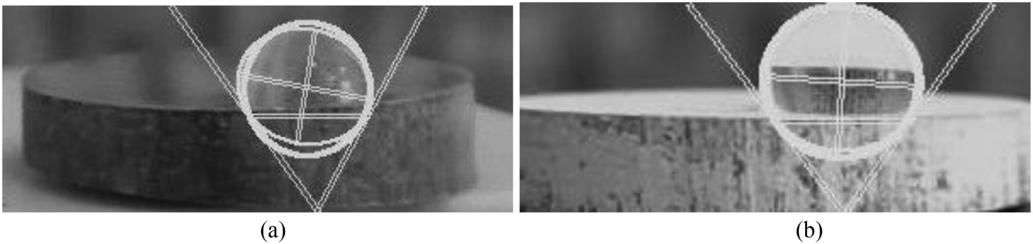
Potentiodynamics results
Corrosion resistance values were attained at various immersion time for the bare sample and ZnO coated alloy. Furthermore, it was found that the immersion time in Ringer's solution considerably changed the corrosion parameters. The electrode potential in a metal–electrolyte system often reflects the condition of metal's surface, when it is immersed in the corrosive medium. The open-circuit potential OCP results in Figure 8 showed that the electrode potential for the bare sample tested in Ringer's solution, with increasing immersion time, was more noble (−0.25 mV) than the samples tested in the Ringer's solution after 1hr (−0.26 mV).
Open circuit potential for ZnO coated Mg and bare ZK60 Mg sample in Ringer's solution w.r.t exposure times.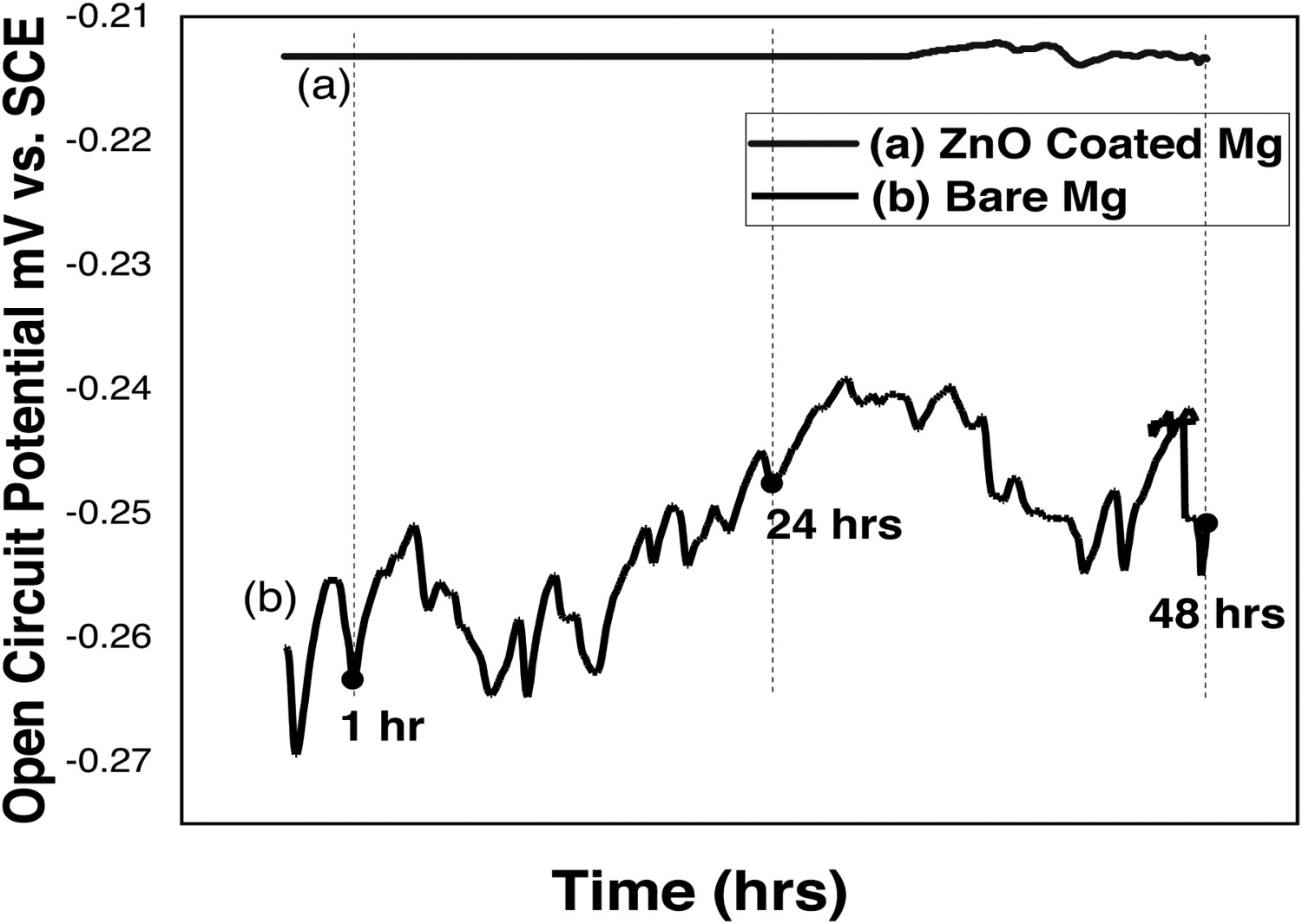
The ZnO coated alloy exhibit a steady pattern in OCP plot, and a straight flat-line trend till 24 h immersion (0.214 mV) and a minor oscillation can seen during 48 h of immersion, showing the formation of a passive layer over-time. It is suggested that the OCP shift in the more noble direction reflects that passive layer formed, serves as a barrier for magnesium alloys dissolution and slows the pace of corrosion. This shift in electrode potential after 24 h in ZnO coated alloy may be caused by the formation of corrosion products on the sample's surface or by the oxide film thickening. The investigated samples become more thermodynamically stable with time, as seen by the open-circuit potential steadiness at start of test and an increase after a 24-hour immersion. This change in shape of OCP plot, mainly oscillations after 24 h, may be associated with certain ZnO layer instability as immersion time increases which can be due to its active dissolution and reformation simultaneously. This demonstrates that zinc oxide is only partially dissolved in Ringer's solution and that corrosion products are deposited on the tested sample's surface, demonstrating anti-corrosion protection and confirming the maximum OCP value.
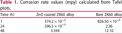
The potentiodynamic test results are in strong agreement with OCP plots. The ZnO coated alloy shows more electronegative OCP values with increasing immersion time according to Figure 9, which resulted in high potential and a faster anodic reaction rate which were ascertained by the Tafel Plot results (Table 1). It can be inferred that a drop-in corrosion rate values determined by Tafel plots that shift towards positive region is related with a decrease in the driving force of the cathodic reaction and an increase in passive layer thickness.
Tafel curves (a) bare ZK60 alloy (b) ZnO coated ZK60 alloy after 1–48 h of immersion in the Ringer's solution Corrosion rate values (mpy) calculated from Tafel plots.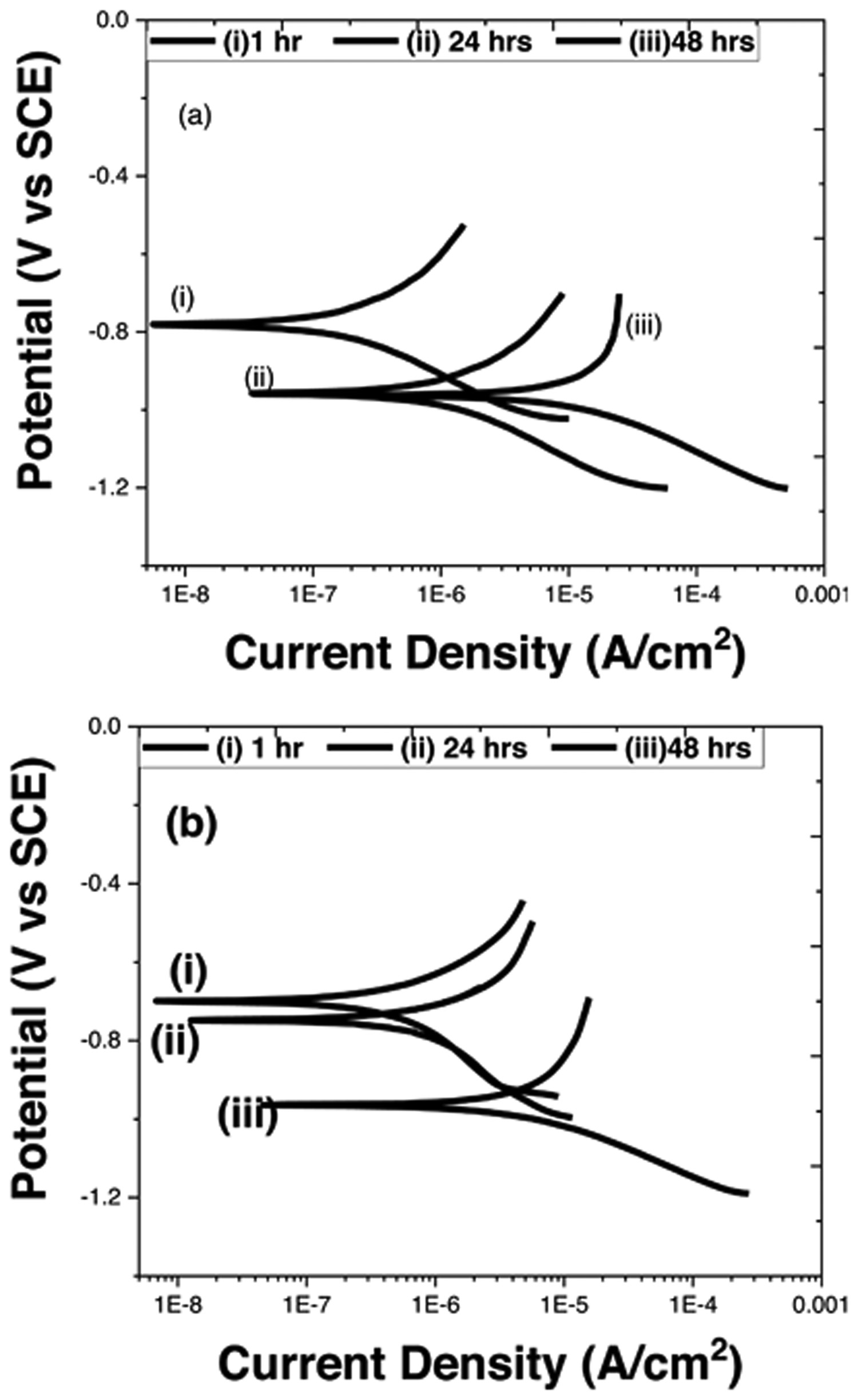
The coated samples were distinguished by higher corrosion potential values, and polarisation resistance Rp. The deposition of the ZnO layer on ZK60 alloy produced a high electrochemically stable oxide layer, as shown by the relatively high value of the polarisation resistance Rp, which is in accordance with the results obtained by EIS method. Equation (1) states that zinc corrosion which involves the metal's anodic dissolution:


The final reaction can be explained as:

It has been stated in literature that the decrease in corrosion rate of zinc is caused by a reduced rate of the cathodic reaction. Moreover, surface oxides serve as a strong anti-corrosion barrier. So, the corrosion products observed on the surface of the ZnO coated alloy may be explained by the fact that metallic zinc will eventually dissolve in physiological conditions. The Zn + 2, that is released from the ZnO coated alloy, into the extracellular space has the potential to biologically incorporate with human tissue or enclosed in a dense fibrous tissue, which could result in an inflammatory response. The healing process, biological compatibility and biostability of the zinc oxide coating are significantly influenced by the cellular response to Zn + 2.
The corrosion resistance of bare ZK60 alloy and ZnO coated alloy in Ringer's solution at 37°C was investigated using electrochemical techniques. Figure 9 depicts the potentiodynamic polarisation curves over time with and without a ZnO coating on ZK60 alloy. The uniform corrosion rate values over time calculated using the Tafel fit by Echem Analyst have been shown in Table 1.
Corrosion resistance is better when the electropositive corrosion potential (Ecorr) is higher. The Ecorr (from −700 to −964 mV) of the ZnO coated alloy was significantly higher than the Ecorr (from −800 to −963 mV) of the bare ZK60 alloy with time. Ecorr shifts in the negative potential direction with increasing immersion time, as shown in Figure 8 and both samples show almost similar pattern. This suggests that coated sample exhibit superior corrosion resistance because it is less susceptible to corrosion than bare sample. The hyperbolic Tafel plot moves towards low current density with immersion time, showing that the adhesion of ZnO coating enhances the anti-corrosion performance.
There was a considerable increase in Ecorr by the use of ZnO coating on ZK60 alloy, which can also be attributed to thermodynamic barrier property provided by ZnO. This Ecorr indicated the exceptional barrier property of coating because of its hydrophobicity, which can prevent the absorption of corrosive species and provides improved corrosion resistance properties. ZnO film could be utilised as a physical isolation barrier to prevent corrosion media from reaching the electrolyte–metal interface, hence improving the sample's corrosion resistance. The drop-in corrosion potential (Ecorr) indicates that the specimen's passivity has been lost due to the diffusion process in the oxide layer caused by the chemical dissolution activity, as the immersion time has been increased. One other reason can also be suggested that chloride ion (Cl−) attack the oxide layer more on the ZnO coated alloy than on the bare alloy. This could also be explained by the discontinuities in the oxide coating caused by Cl− ions attacking on the alloy surface.
Increase in immersion time leads to an increase in corrosion current density (icorr) and rate. As a result, the ZnO coated alloy has greater corrosion resistance since its corrosion current density is around four times lower than that of the bare alloy. The current densities after 24- and 48-hours immersions are almost an order of magnitude lower than for the bare ZK60 alloy, and the anodic curve's slopes are substantially steeper.
Electrochemical impedance spectroscopy results
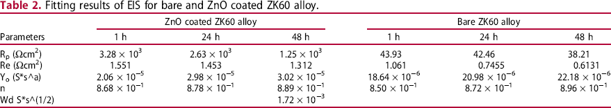
Nyquist plots for ZnO coated alloy and bare alloy after 3 days in Ringer's solution at 37°C have been shown in Figure 10(a and b) and electrical equivalent circuits model that fits well to the experimental results has been displayed in Figure 11(a and b). Table 2 contains the values of the fitted parameters for equivalent circuit models.
Nyquist plots of (a) Bare ZK60 alloy and (b) ZnO coated ZK60 alloy in the Ringer's solution after 1–48 h of immersion along with fit data based on the models illustrated in Figure 9(a and b), respectively. Equivalent circuit of fitting EIS data for (a) Bare ZK60 Mg alloy & ZnO coated Mg alloy (b) ZnO coated Mg alloy after 48 h. Fitting results of EIS for bare and ZnO coated ZK60 alloy.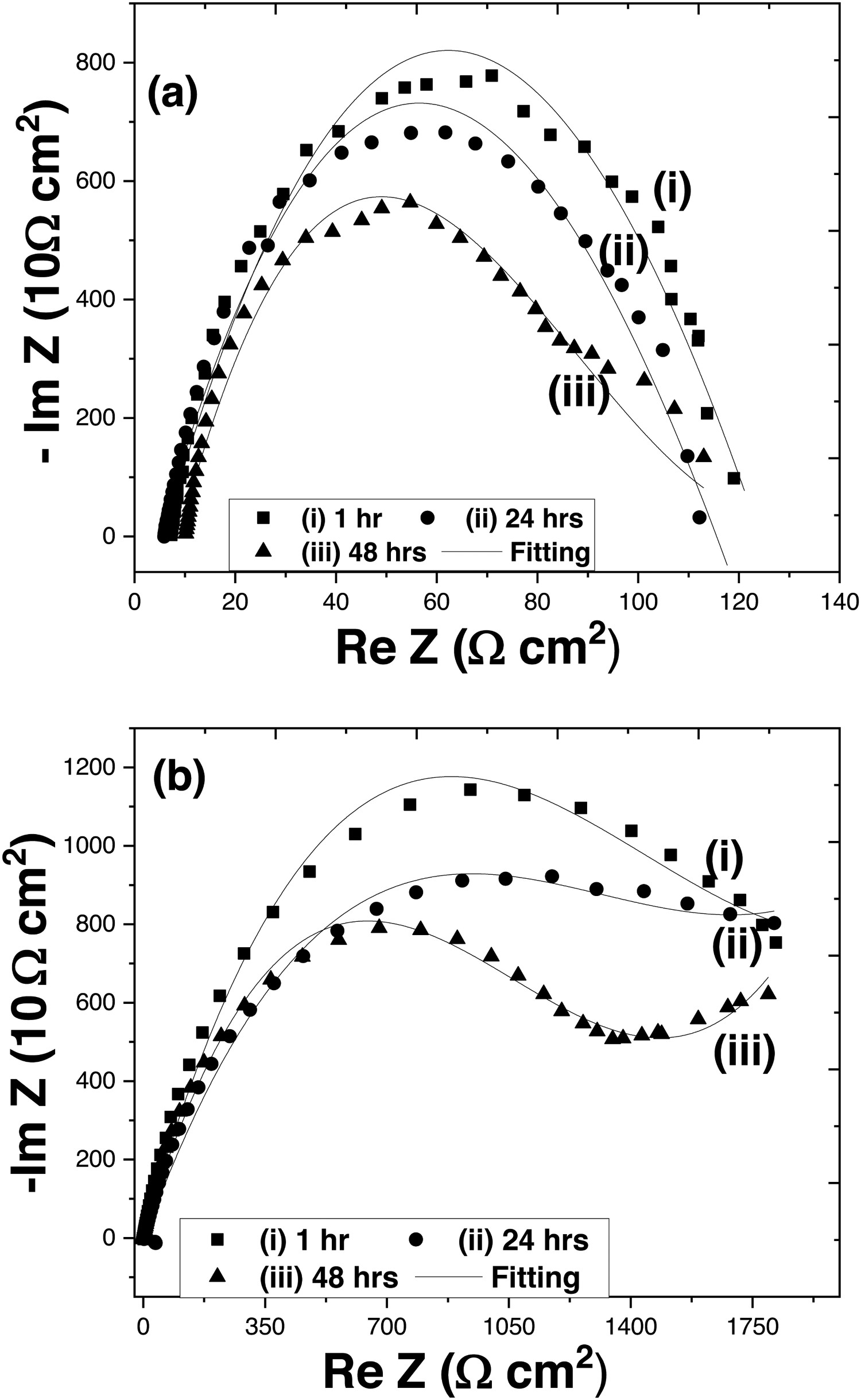
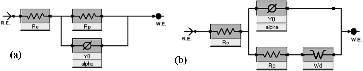
Nyquist plot for ZnO coated Mg alloy depicts higher capacitive semicircle and greater overall impedance compared to the bare ZK60 Mg. Nyquist impedance plots are characterised by one well defined loop. The features of the electric double layer that forms at the interface between the corrosive product and substrate constitutes a high frequency capacitive loop [33]. Re is the electrolyte resistance between the substrate and reference electrode. CPE and Rp denotes capacitance of corrosion product on the surface of substrate and the corresponding resistance Rp is associated with the corrosion products defects respectively [34]. Wd is the Warburg diffusion element sufficient to explain the diffusion phenomenon in EIS data. This Warburg impedance is due to a combination of kinetic and diffusion processes. The CPE dispersion power is represented by the parameter n, which ranges from 0 to 1, and measures the deviation from perfect capacitive behaviour. CPE operates as an ideal capacitor when n = 1. If n < 1, the substrate system is inhomogeneous due to the factors like roughness, porosity or an uneven distribution of the current [35].
The coated alloy form imperfect semicircles with a fairly broad radius of curvature compared to bare alloy during the first two days of experiment, indicating capacitive behaviour, which is the typical characteristics of passive coated materials. The capacitance arc radius of both ZnO coated and bare alloy decreased as the immersion time was increased, as evidenced by Nyquist plot; similarly, the impedance modulus decreased in the Bode plots. For ZnO coated alloy, ZnO coating layer on the surface of the magnesium alloy was responsible for this drop, when the metal was immersed in Ringer's solution environment. The chloride ions eventually penetrated the surface of metal and reacted with the oxide covering as the immersion time increased (due to the high chloride concentration in Ringer's solution), causing the dissolution/diffusion of oxide coating. The corrosion of magnesium alloy was predominantly governed by the charge transfer process at the beginning of immersion, as demonstrated by the impedance spectroscopy of ZnO coated alloy. At the impedance plane, a capacitive impedance arc with significant diameter is formed (the capacitive arc diameter was more than 1150 ohms.cm2), and there was just one time constant in the electrochemical impedance spectrum, as illustrated in Figure 9(a). The diameter of capacitance arc reduced steadily with increased immersion time, and the high phase angle area also shrank with time. The ZnO coating had been attacked by chloride ions in solution by the third day, resulting in a capacitance arc diameter of only 790 ohms.cm2. The chloride ions moved towards the sample's surface when the immersion time was increased further, causing the passive coating on surface of metal to dissolve showing uniform corrosion as depicted by SEM results.
The polarisation resistance decreases from 3.28 × 10³ to 1.254 × 10³ Ωcm2 and the capacitance parameter Yo increased from 2.06 × 10⁻⁵ to 3.02 × 10⁻⁵ S.sn with time for ZnO coated alloy. The polarisation resistance decreases from 43.93–38.21Ωcm2 and the parameter for capacitance Yo rose from 18.64 × 10⁻⁶ to 22.18 × 10⁻⁶ S.sn with time for bare ZK60 alloy. This demonstrates that the initial electron transfer is slower for metallic materials and that a higher polarisation resistance Rp is associated with stronger corrosion resistance and slower rate of corrosion. The passive layer exponent n decreases with increase in time suggesting that the passive layer is losing its surface homogeneity with increasing time. Warburg diffusion element Wd in Figure 11(b), added to the phenomenon in ZnO coated sample, has a lower value, justifying that a significant amount of electron transfers occurs as the immersion time is increased indicating that the diffusion has started at surface of coated layer.
The Bode plot (Figure 12(a)) in impedance module Z format shows that the coated sample has a significant level of passivation from 1 to 72 h, followed by a drop-in capacitive behaviour until the completion of test. Furthermore, the Bode plot in phase angle (°) format demonstrates the formation of a single set of time constant in the medium frequency (10–10 KHz) range.
Bode plots of (a) Bare ZK60 alloy and (b) ZnO coated ZK60 alloy in the Ringer's solution after 1–48 h of immersion along with fit data based on the models depicted in Figure 9(a and b), respectively.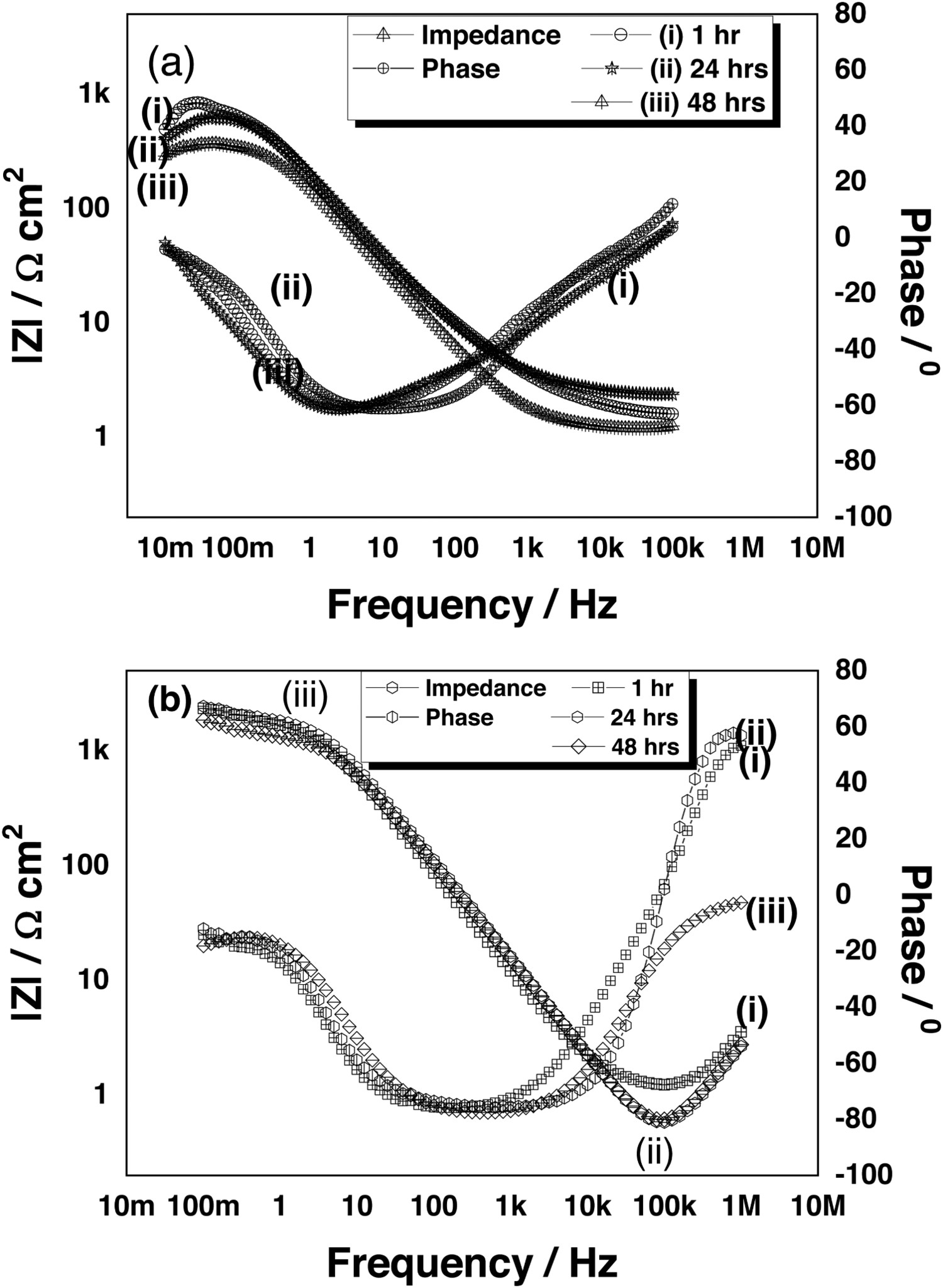
At the beginning of the experiment, the medium frequency range time constant for phase angle values is between 80° and 70°.
The time constant associated with phase angle values is between 80° and 70° in medium frequency range at the start of experiment. However, as the test progresses (3 days), the time constant indicates decreasing phase angle values for the medium frequency band, ranging from 69° to 64°. The high phase angle values of the ZnO coated passive layer at the start of the test were due to the barrier-like effect created by the ZnO coating on Mg alloy, which prevented the Ringer's solution from making contact with the ZK60 free surface (i.e. a phase angle of 80° suggests that the metallic surface is adequately isolated from environment due to the presence of coating) [36]. The higher phase angle of 60° indicates the thickness of protective layer of ZnO and its adhesion to the substrate as compared bare alloy as shown in Figure 10(a and b).
SEM after electrochemical testing
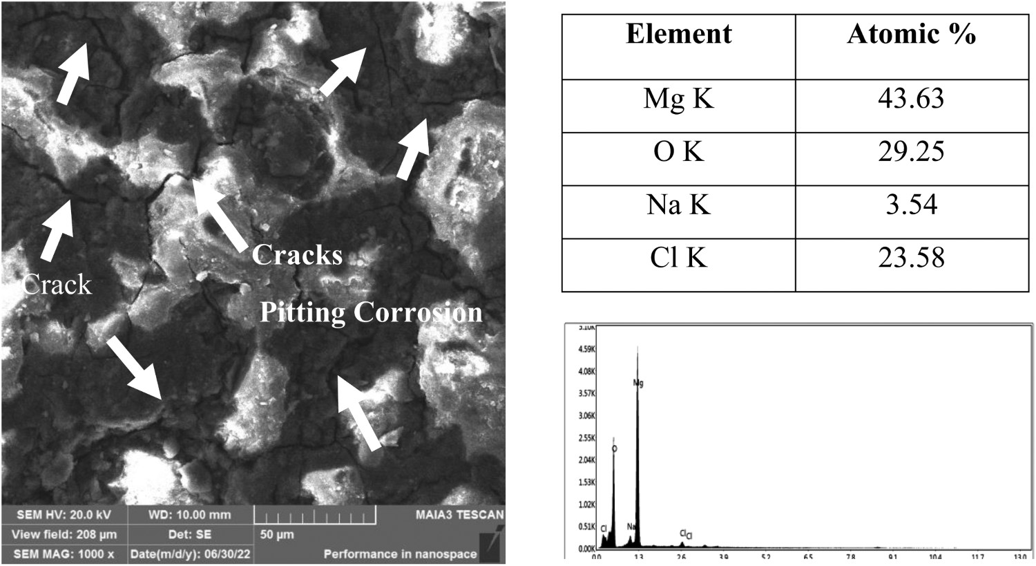
The top surface morphology of bare alloy has been shown in Figure 13. There were noticeable large cracks on the surface of alloy after the corrosion tests. The exposed bare specimen's surface micrograph revealed that it had completely corroded and that the pitting corrosion had initiated after it had been submerged for 48 h in Ringer's solution and the alloy had undergone distortion after its exposure in the Ringer's solution. It is generally accepted that the anodic dissolution of magnesium and the cathodic evolution of hydrogen take place in accordance with the following equations, when bare ZK60 Mg alloy is immersed in Ringers’ solution.
SEM image of bare ZK60 alloy after corrosion test in Ringer's solution.

The final reaction can be explained as:

The insoluble magnesium hydroxide (Equation 6) that forms on the surface of the ZK60 alloy is transformed into a highly soluble MgCl2 due to the high chloride content (approximately 0.15 M) in Ringer's solution (Equation 7).

The EDS analysis shows high Cl atomic percentage on ZK60 alloy surface that formed after 48 h of immersion in Ringer's solution, which may be connected to the accelerated migration of chloride ions towards the metal–oxide contact. It has been reported in previous studies that the development of metal chlorides on magnesium alloys in contact with simulated body fluid solution causes the corrosion layer to mechanically rupture because of higher molar volume of chloride ions [37].
The buildup of metal chloride at the metal interface should be taken into consideration as a promoter of the rupture of the oxide coating and in the nucleation and propagation of developing pits, even though the causes are yet unknown [36]. Therefore, one could presume that the significant Cl content in the form of magnesium chlorides salts, on ZK60 alloy after 48 h immersion in the Ringer's solution (37°C), promotes the formation of corrosion products with poorer protection properties and the increase in the tendency for pitting (Figure 13).
SEM images of the exposed ZnO coated alloy after immersion in Ringer's solution (as in Figure 14) displayed the flattened splats, proving that it has maintained its morphology despite the corrosion testing (spherical-shaped particles). The top surface of the ZnO coated alloy showed no signs of cracks after corrosion testing in Ringer's solution. However, some micropores were found in their microstructure, and the covering had some voids between the splats. The coating-substrate contact looked to be defect free. It shows the uniform corrosion as major corrosion mode and also shows uniform coating, as pitting is expected in case there are areas not coated.
SEM image of ZnO coating after corrosion test in Ringer's solution.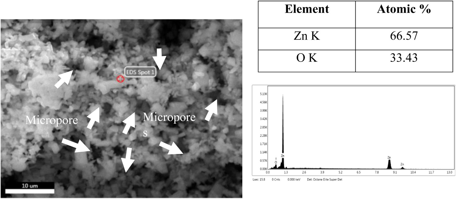
Conclusion
ZnO ceramic coating formed on ZK60 magnesium alloy was done by electrophoretic deposition in a propanol solution. The coating's composition, structure, and corrosion behaviour in Ringer's lactate solution was studied and compared with bare alloy. The coating produced in the basic suspension was continuous, had a fine-grained structure, with no visible pores or cracks, and was primarily made of ZnO. ZnO coating demonstrated better resistance to corrosion in polarisation tests compared to the bare alloy after (1h-48 h) exposure in the Ringer's solution. The results showed that the ZnO coating provides a significant stable corrosion-resistant layer than the bare alloy at different immersion times. ZnO coating on Mg alloy significantly improved the hydrophobicity and corrosion resistance as compared to the bare samples. The maximum phase angle and impedance value and were around 30% higher in ZnO coated alloy in comparison to bare Mg-alloy. The corrosion rate of ZnO coated Mg-alloy is lowered by 72% when compared to bare ZK60 Mg-alloy after 48 h of immersion in Ringer's solution. This demonstrates that the ZnO coating is more protective and compact than that of Mg-alloy without coating, thus increasing in bioactivity. The cracks were developed on the bare alloys surface, whereas, the surface of the ZnO coated alloy showed no signs of pitting.
Footnotes
Disclosure statement
No potential conflict of interest was reported by the author(s).