
Abstract
The study reports the formation of multilayer coatings of CrN with variable gradient modulus on TC4 substrate by varying the discharge current of the hot filament in magnetron sputtering. Results show that multilayer CrN/TC4 has a higher critical failure load (63.4 N > 29.7 N), lower maximum tensile stress (103.8 GPa < 134.3 GPa), and a higher ratio of plastic to elastic deformation work (Wp/We, 2.11 > 1.58) than a single layer CrN/TC4. This indicates that the energy absorption ability of the coating/substrate before failure can be improved by increasing the loose energy-absorbing sublayer, thus improving the coating/substrate adhesion. Notably, the wear rate of both multilayer and single-layer coatings is in the order of 10−16 m3/(N·m), demonstrating their excellent wear resistance. Structural engineering enables the application of multilayer CrN coatings on low-modulus and high-strength alloy substrates, such as TC4.
HIGHLIGHTS
A dense-porous multilayer coating obtained by varying the filament discharge currents. The modulus difference between the multilayer CrN and TC4 reduced. The maximum tensile stress appeared at the interface of the Cr and CrN layers. The multilayer CrN/TC4 with high Wp/We and absorption ability of deformation work. The multilayer CrN/TC4 was with high adhesion and excellent wear resistance.
Keywords
Introduction
Among known metals, pure titanium and titanium alloy have unique characteristics, such as high specific strength, low density, and good corrosion resistance, and they are emerging structural and functional materials [1,2]. Pure titanium and titanium alloy are widely used in fields such as aerospace engineering [3] for reducing structural weight and improving thrust–weight ratio and in fields such as shipbuilding [4], petroleum [5] and chemical industries [6], automobiles [7], and medicine [8,9]. However, they still have some inherent defects, such as poor wear resistance and poor thermal conductivity [10,11], affecting the safety and reliability of their workpiece. Surface modification is considered an effective means to increase the wear resistance and thermal conductivities of titanium and titanium alloys [12].
Metal nitrides, represented by CrN, are used as surface-strengthening coatings for workpieces to their high strength, toughness, and oxidation and wear resistances, which significantly improve the service performance of the workpiece surfaces and render CrN excellent surface protective coating materials [13–16]. However, the application of single-layer CrN/Ti6Al4 V (TC4) is not ideal, as the deformation of the coating and substrate is not coordinated. Therefore, the coating can easily crack or spall and exhibit other signs of failure [17,18]. A study has shown that the high ratio of the plastic to elastic deformation work (Wp/We) of a coating/substrate system indicates high plastic and low elastic deformation energy absorption abilities, and the adhesion between the coating/substrate is higher in such cases [18]. The lower the difference between the moduli of a coating and its substrate, the lower the elastic deformation work associated with them. Ceramic nitride coating is not expected to exhibit plastic deformation and should have a high modulus. Therefore, decreasing the modulus of a coating can decrease the elastic deformation work and increase the Wp/We ratio.
Hot-filament-enhanced magnetron sputtering technology considers a tungsten filament as an auxiliary ionisation source based on a non-equilibrium magnetron sputtering system. A tungsten filament can emit hot electrons and promote argon ionisation such that numerous Ar+ ions bombard the target, promote target sputtering, and increase the plasma density. A high ion density increases the probability of adsorption particles being bombarded in the process of coating growth, thereby increasing the filling probability of the column gap and the film density. In other words, under this condition, the ion current density reaching the substrate can be effectively regulated by adjusting the discharge current of the hot wire such that a gradient multilayer coating with a variable modulus is obtained.
In this study, a hot wire plasma-enhanced magnetron sputtering technique (PEMS) was used to prepare CrN coatings to obtain an engineered multilayer structure by adjusting the hot filament discharge currents [19,20]. The engineered multilayer structure was prepared as follows: First, a pure metal Cr transition layer was deposited on the surface of the TC4 substrate. Relatively loose and dense alternating CrN sublayers were then deposited on the top of the transition layer. Finally, a dense sublayer is obtained. A multilayer CrN coating with a variable gradient modulus was obtained by adjusting the discharge currents to control plasma densities during the magnetron sputtering procedure. Consequently, the difference between the moduli of the engineered multilayer coating and TC4 alloy decreased. Meanwhile, the dense CrN sublayer on top of the coating maintained its wear resistance. A dense single-layer CrN coating was also prepared using the PEMS technique at a relatively high discharge current as a reference coating for comparison with the multilayer coating. Figure 1 shows the structural diagram of the multilayer CrN coating.
Structure schematic diagram of the multilayer CrN.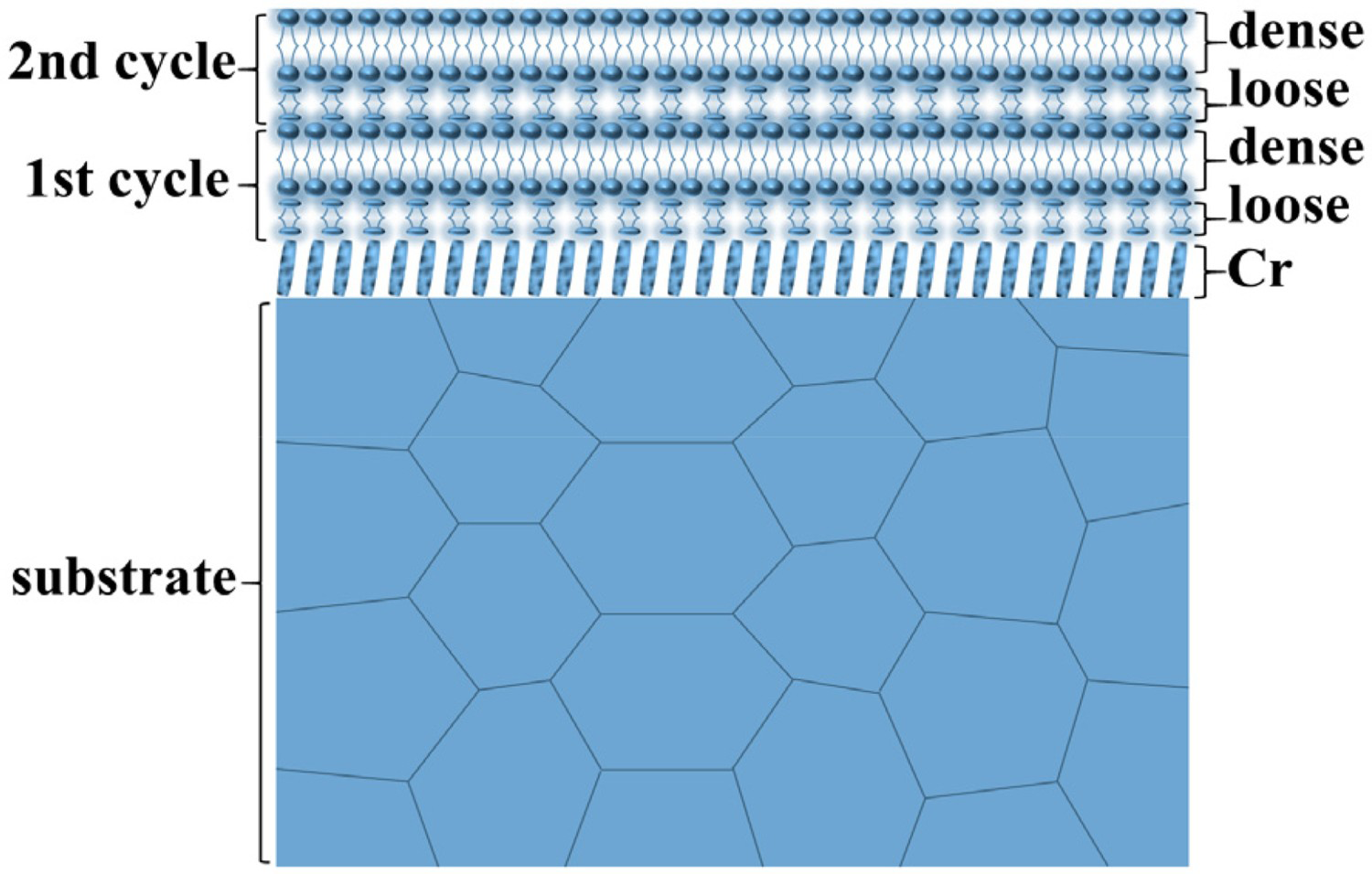
Materials and methods
Coating deposition
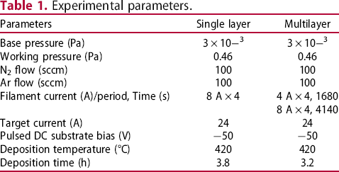
Experimental parameters.
Characterisation of coatings
Field-emission scanning electron microscopy (FESEM, model Apreo 2S) at a working voltage of 15 kV was used to characterise the microstructure of the coating. X-ray diffraction (XRD, model X-Pert Powder) was used to characterise the crystal structure and phase composition of the coating in a wide-angle θ–2θ scanning mode, with scanning angles ranging from 20° to 100° and scanning time lasting 8 min. The hardness (H) and elastic modulus (E) of the TC4 titanium alloy and CrN coating were determined using the Oliver Pharr method on Nano Indenter G200, and the indentation depth was set at 2000 nm. The plastic deformation work (Wp) and elastic deformation work (We) were calculated by integrating the loading and unloading curves. Rockwell indentation was used to test the adhesion of the coating/substrate at 1470 N per the VDI3198 German standard [19]. A multifunctional surface tester (model: MFT-4000) with a diamond indenter (cone Angle: 120°) was used for scratch detection. The scratch length was set at 5 mm, and the loading rate was set at 100 N/min. The indentation and scratch morphology of the coating/substrate were characterised using an ultra-depth-of-field microscope (model: VHX-5000). A friction and wear testing machine (model: MS-T3001) was used to test the wear resistance of the coating/substrate. The grinding ball was made of zirconia and had a diameter of 4 mm. The motor speed was set at 200 r/min, load at 300 g, wear radius at 3 mm, and test time at 1 h. A probe profilometer (model: Alpha-step D-100) was used to characterise the thickness of the coating and the abrasion profile.
Simulation model definition
In the commercial finite element software ABAQUS 2016 edition, a 3D dynamic modelling method was used to simulate the deformation process and interfacial stress of the coating/substrate under impact loads. In the pressing process, the indenter is regarded as a rigid body and does not undergo deformation behaviour. The coating is a ceramic material; therefore, it is defined as a brittle material, and the substrate is regarded as an elastic–plastic material. The cross section of the sample was measured via nanoindentation, and the elastic moduli of the coating and substrate were obtained. The modulus of the single-layer CrN coating was 311.2 GPa, and the moduli of the loose and dense sublayers of the layered multilayer CrN coating were 239.3 and 321.2 GPa, respectively. The modulus of the substrate was 140.3 GPa. Some studies have shown that the flow stress behaviour of the substrate can be defined according to the Johnson–Cook (J–C) material model [21].
The coating/substrate system was completely fixed in the global coordinate system to ensure that the position of the coating/substrate system did not shift during stress. Considering the Rockwell indentation load (1470 N) as a reference, the load applied to the indenter during axisymmetric modelling was 735 N. The contact between the indenter and coating/substrate was defined as the surface-to-surface contact mode in the ABAQUS interaction module. The indenter was defined as the primary surface, and the coated surface was defined as the slave surface because, in the definition of face-to-face contact, the rigid surface should be selected as the primary surface and the deformable body as the slave surface. The contact property of tangential behaviour was set as a penalty contact, wherein the friction coefficient between the indenter and coating can be set to render the contact effect real. The normal behaviour was set as ‘hard’ contact, that is, when the contact pressure between the indenter and coating was zero, the two contact surfaces were separated, node constraint was released, and corresponding state setting was after the indenter was not pressed or completely lifted.
The grid division of the indenter and coating/substrate system was performed depending on the characteristics of the grid. A hexahedron grid is highly accurate and difficult to divide. Therefore, the grid of the coating/substrate system with a large deformation and high calculation accuracy was divided into linear hexahedrons, whereas triangular and quadrilateral grids had poor calculation accuracy but high adaptability to complex models. Therefore, the grids of the indenter which did not participate in numerical analysis and had slightly complex shapes were divided into a combination of linear triangles and quadrilaterals.
Results and discussion
Structure and morphology
The morphological and phase structures of the multilayer and dense single-layer CrN coatings are shown in Figure 2. The surface morphology of the multilayer CrN coating (Figure 2(a)) was a uniform polygon and that of the dense single layer was packed (Figure 2(b)). The two periodical loose and dense sublayers observed in the cross-sectional morphology in the multilayer CrN coating and the dense fine columns in that of the single CrN coating are shown in Figure 2(c) and (d), respectively. The interfaces between loose and dense sublayers were marked by red dotted lines with a thickness ratio of 1:2. After adjusting the discharge current of 4 A × 4, the thin sublayer had a loose structure and therefore a darker colour, and after adjusting the discharge current of 8 A × 4, the thick sublayer had a tight structure and therefore a brighter colour. The XRD diffraction patterns of the coatings and substrate in Figure 2(e) show the primary diffraction orientation of CrN (111) and three low diffraction peaks of CrN (200), (220), and (222). Both coatings had a thickness of approximately 5.7 µm and were sufficiently thick to prevent the diffraction peaks of the TC4 substrate. Because the total discharge current of the single-layer coating was greater than that of the multilayer coating, the CrN (111) of the single-layer coating was higher than that of the multilayer coating.
Multilayer (a) and single layer (b) surface, multilayer (c) and single layer (d) cross-sectional morphologies of the CrN coatings, XRD patterns (e) of the coatings and substrate.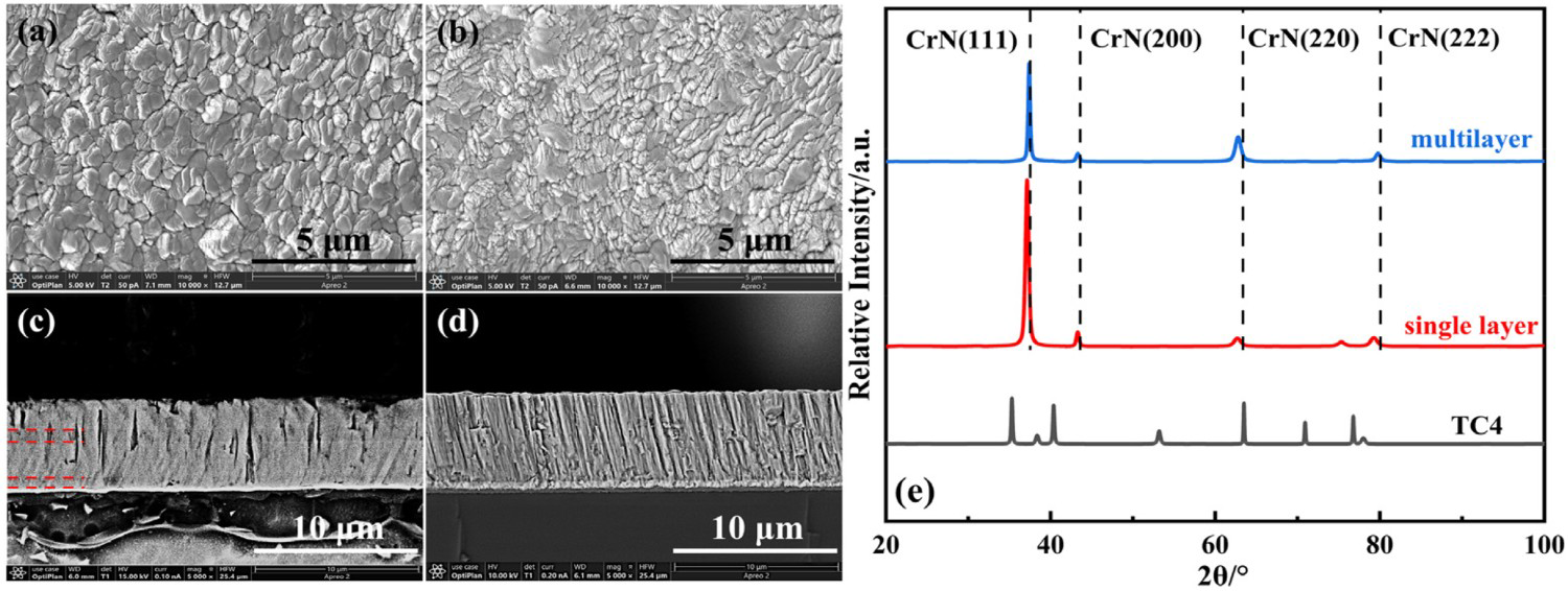
Mechanical properties and wear resistance
Figure 3 shows the hardness (a) and elastic moduli (b) of the CrN coatings and substrate as a function of pressing depth in a nano-indentation test.
Hardness and elastic modulus of the coatings and substrate: (a) hardness; (b) modulus.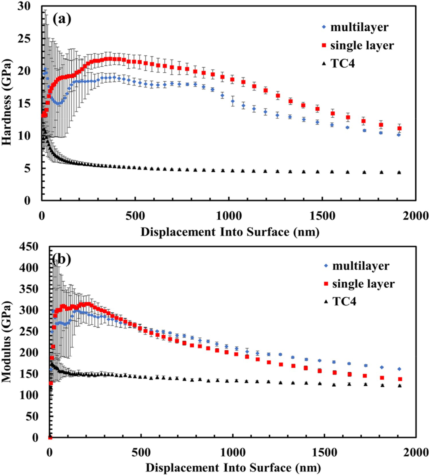
Properties of the coatings and substrate.
Note: E* = E/(1−v2), Poisson's ratio: CrN = 0.23, TC4 = 0.34.
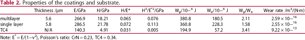
The wear morphologies and profile plots re shown in Figure 4a, the CrN coatings, and Figure 4b, TC4 substrate, the wear rates in Table 2. The wear profile of TC4 is significantly wider and deeper than those of the CrN coatings. The calculated wear rates of the single and multilayer CrN coatings are in the order of 10−16 m3/(N·m), approximately three orders lower than the 9.22 × 10⁻¹³ m3/(N·m) of the TC4 substrate. The dense CrN coating could significantly improve the wear resistance of the TC4 substrate. Because the surfaces of the single and multilayer coatings were dense structures prepared by the discharge current 8A × 4, their wear rates were approximately equal.
Wear morphologies and profiles of the (a) CrN coatings and (b) TC4 alloy.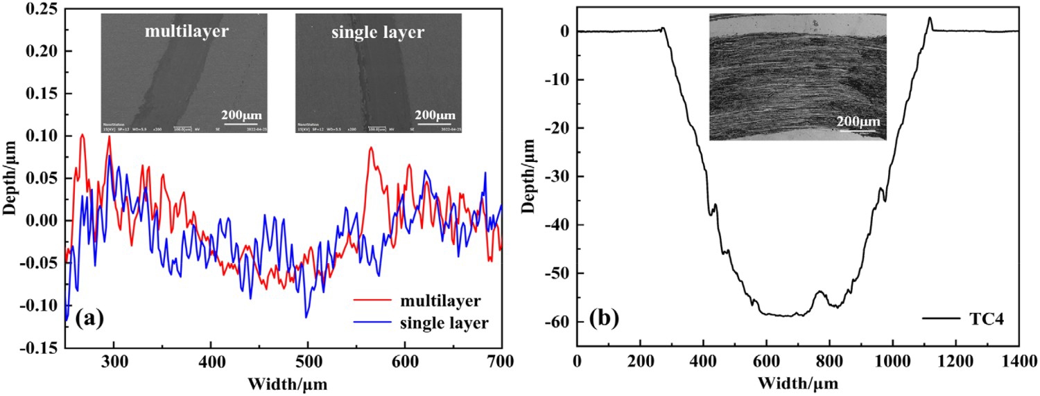
Adhesion and failure analysis
The Rockwell indentation morphologies, scratch acoustic signal curves, and morphologies of the multilayer and single layer CrN/TC4 are shown in Figure 5 (a), (b), (c), and (d), respectively. Circumferential cracks were observed only around the indentation of the multilayer CrN/TC4 with the adhesion between CrN/TC4 of the HF1 grade, per the VDI3198 German standard. The partial peel-off of the single-layer CrN coating from the TC4 substrate was noticeable from the indentation of the single-layer CrN/TC4, and the adhesion grade was HF5.
Rockwell indentation topographies of the (a) multilayer and (b) single layer, scratch acoustic signal curves and topographies of the (c) multilayer and (d) single layer CrN coatings.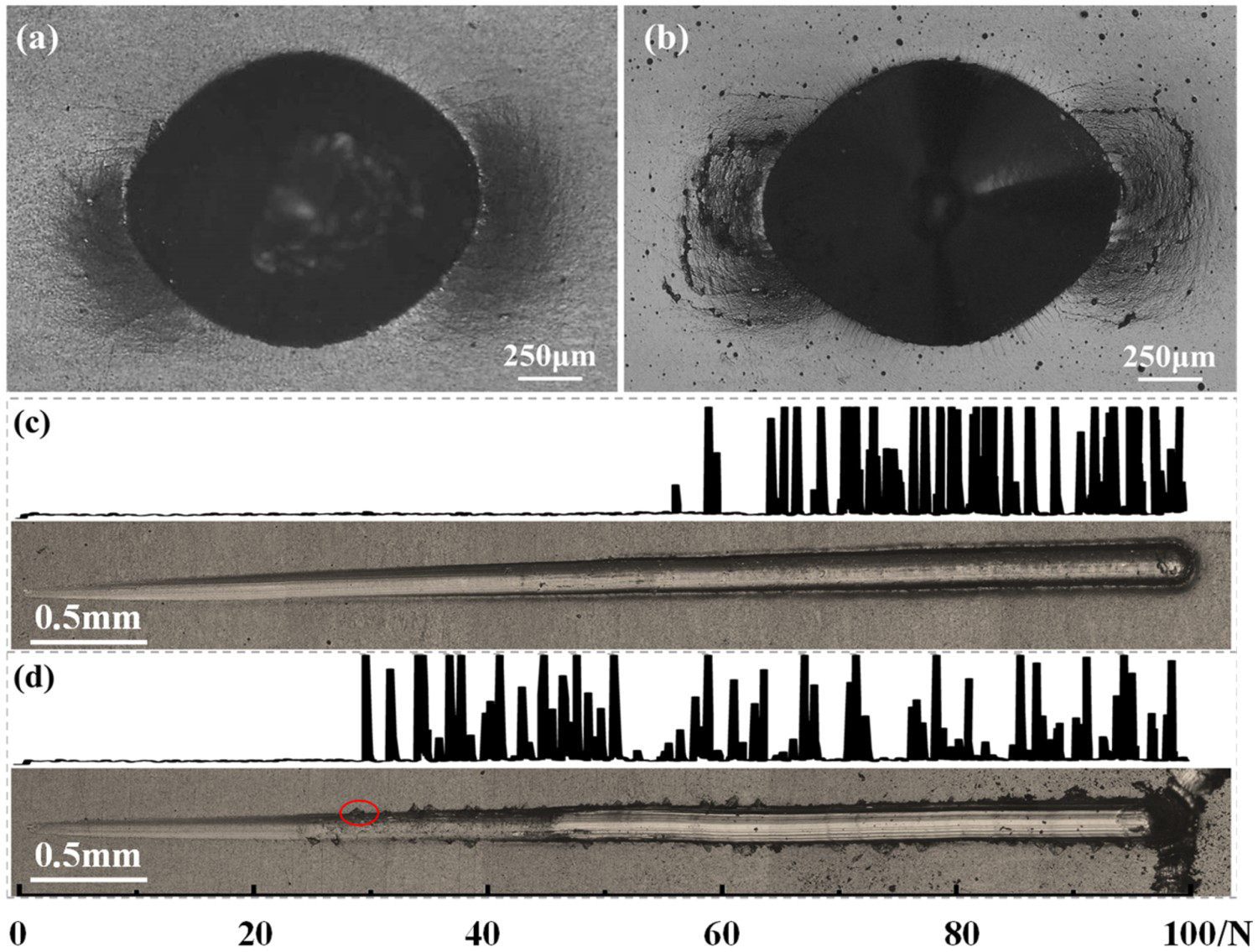
The acoustic signals of the multilayer CrN/TC4 first fluctuated at a load of 56.2 N, and subsequently, the fluctuation became stable after a load of 63.4 N. No coating chip was noticeable at the corresponding scratch edge, as shown in Figure 5(c). The acoustic signals of the single-layer CrN/TC4 began to fluctuate at a load of 29.7 N, and coating chips were observed at the corresponding scratch edge, as shown by the red circle in Figure 5(d). Therefore, the critical load (29.7 N) of the single-layer CrN/TC4 was significantly lower than that (63.4 N) of the multilayer CrN/TC4. The hard single-layer CrN coating on the TC4 alloy bore only an extremely low critical load before its failure from the substrate, which does not meet the desired standard of a hard yet tough coating.
The load–displacement depth curves of the coatings and substrate are shown in Figure 6. Wp, We, and Wp/We of the coatings and substrate were calculated by integrating the curves, as presented in Table 2. The 380 × 10−6 J Wp of the multilayer CrN/TC4 was approximately 20 × 10−6 J higher than the 360 × 10−6 J of the single-layer CrN/TC4, indicating that the high plastic work transferred into the plastic energy during the plastic deformation between the multilayer CrN/TC4. The 180 × 10−6 J We of the multilayer CrN/TC4 was approximately 50 × 10−6 J lower than the 228 × 10−6 J of the single-layer CrN/TC4. The low elastic modulus difference and good co-deformation caused the multilayer CrN/TC4 system to have high plastic energy absorption capacity and low elastic work generation capacity. Therefore, the 2.11 Wp/We ratio of the multilayer CrN/TC4 was higher than the 1.58 of the dense single-layer CrN/TC4, demonstrating the excellent adhesion between the multilayer CrN/TC4.
Load-displacement curves of the coatings and substrate.
The numerical simulations of the stresses at the interfaces between the CrN/TC4 are shown in Figure 7. The results showed that tensile stress occurred at the edge of the indentation, which was consistent with the position of crack generation in the Rockwell indentation surface topography of the coating. Moreover, a stress cloud map showed that the influence area of the multilayer coating was smaller than that of the single-layer coating, confirming the experimental result that the degree of damage at the indentation edge of the multilayer coating was smaller than that of the single-layer coating. Further observation showed that the maximum tensile stresses were generated at the interfaces between the CrN coatings and their transition Cr layers, indicating that cracks or slides and other failure behaviours were initiated at the interface between the ceramic sublayer and transition metal layer. The maximum tensile stress of the multilayer CrN/Cr/TC4 was 72.8 GPa, which was significantly lower than the 134.3 GPa of the dense single-layer CrN/Cr/TC4. This was consistent with the results of the Wp/We ratio and also indicated high energy absorption ability, good co-deformation ability, and therefore the excellent adhesion of the multilayer CrN/TC4 system.
Stress cloud map of the (a) multilayer and (b) dense single layer CrN/TC4.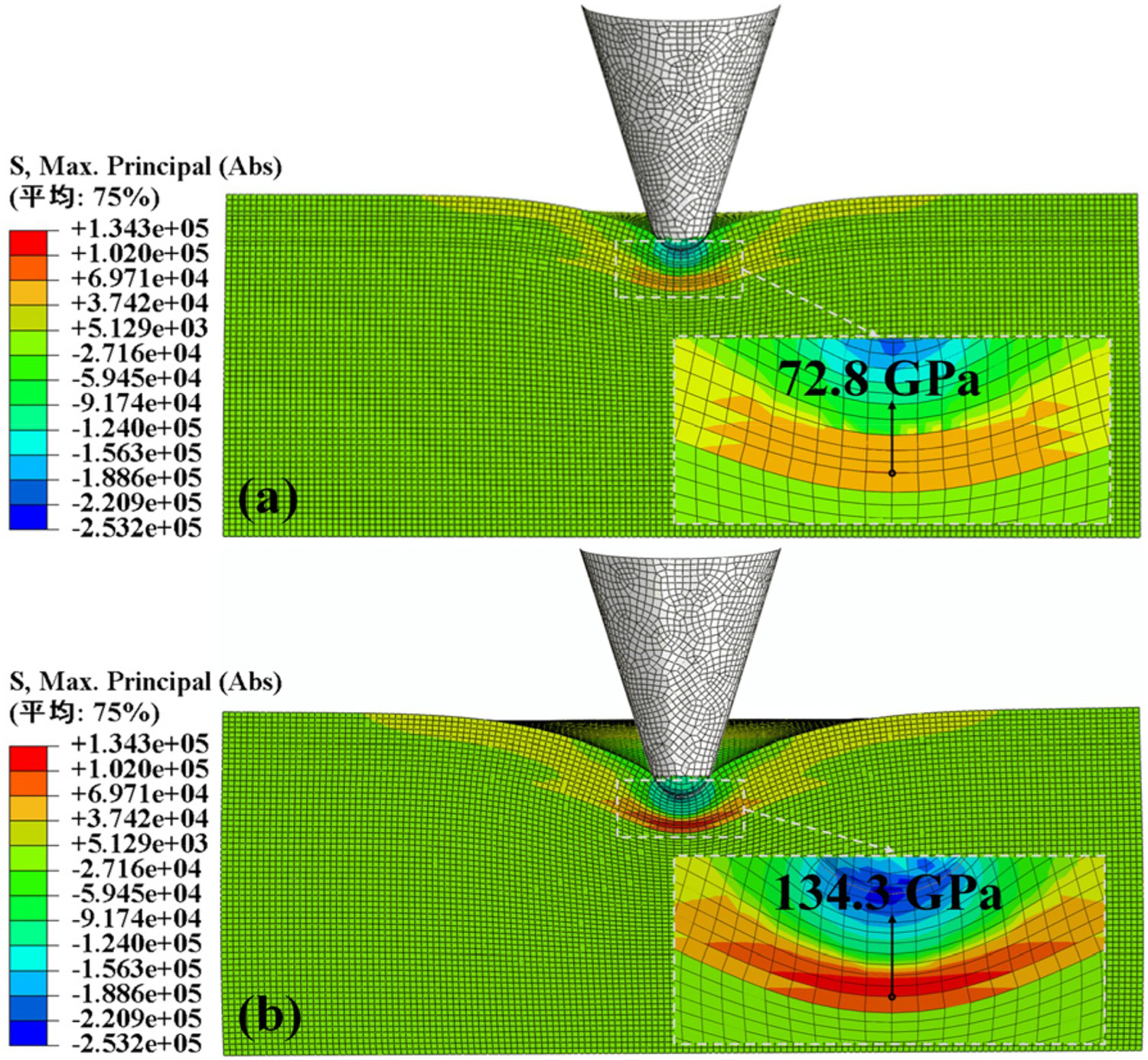
Generally, the structure of the CrN coating should be engineered to facilitate its adaptation to its alloy substrates. Although the hardness and modulus of the multilayer CrN coating were lower than those of the single-layer CrN coating, the multilayer is significantly more suitable for deposition on the TC4 substrate to obtain better adhesion than the dense single-layer CrN coatings without compromising on its wear resistance. The improvement of the adhesion between the multilayer CrN/TC4 was a result of the decrease in the modulus difference between a coating and its substrate, resulting in the high absorption ability corresponding to the plastic deformation energy and low elastic work produced during the deformation of the multilayer CrN/TC4 system. However, the discharge current span during the preparation of the sublayers of the designed multi-layer coating is still large, and the subsequent research plan will consider reducing this span and adopting N2 gradient regulation for the transition metal layer, with the central idea being to reduce the inter-layer stress and reduce the risk of failure.
Conclusions
In this study, we prepared a multilayer coating with a modulus gradient and a dense single-layer coating with uniform modulus on a TC4 substrate by adjusting the discharge current on a hot wire to enhance magnetron sputtering while controlling plasma density. The results showed that the critical failure load of the dense single-layer CrN coating on the TC4 substrate was 29.7 N, which was significantly lower than that of the multilayer CrN coating. Numerical simulation results showed that the maximum tensile stress (72.8 GPa) of the multilayer CrN/Cr/TC4 was less than that of the single-layer CrN/Cr/TC4 (134.3 GPa) and that a large tensile stress resulted in coating failure. The Rockwell indentation morphology showed that a large area of peeling appeared around the indentation of the single-layer CrN/TC4, whereas the indentation morphology of the multilayer CrN/TC4 was unchanged. The Wp/We of the multilayer CrN/TC4 was 2.11, which was higher than that of the dense single-layer CrN/TC4 (1.58), indicating that the multilayer coating had a high absorption capacity for plastic deformation before failure. Notably, the wear rates of the multilayer CrN coating with high adhesion to the substrate and the dense single-layer CrN coating were in the order of 10−16 m3/(N·m); thus, both coatings exhibited excellent wear resistance. The gradient multilayer CrN coating prepared by adjusting the discharge current can reduce the modulus difference with the substrate and improve the adhesion with the substrate while maintaining high wear resistance. This structural engineering enables the multilayer CrN coating to be applied to alloy substrates, such as TC4, with high yield ratios.
Footnotes
Disclosure statement
No potential conflict of interest was reported by the author(s).