
Abstract
The locally introduced heating and cooling cycle of welding generates residual stresses and distortion. Costly post-weld heat treatments are required in order to reduce welding residual stresses and distortion. Thermal tensioning is one of the more promising in-process techniques to control welding distortion and can be classified into transient thermal tensioning (TTT) and side heating (SH). In thermal tensioning additional heat sources are applied during welding. If the additional heaters are close to the weld centre line and influence the thermal field of the weld, the process is called TTT. If there is no interference to the thermal field of the weld, the process is called SH. In this work, the SH during welding of 2 mm thick DP600 steels has been extensively investigated using numerical and experimental approaches. The thermal and mechanical fields during conventional welding and SH were examined by means of finite element models, and validated by comparison with experimental observation of temperature, distortion and residual stresses. The microstructure was investigated experimentally.
Background
Welding involves local heating and cooling of the workpiece. During the heating and the cooling cycles, the material experiences non-uniform expansion and contraction. Furthermore, the material might undergo plastic deformation, phase transformations, recovery and recrystallisation. All these phenomena, in combination with the constraints imposed, contribute to the formation of stresses within the workpiece, which may cause permanent welding distortion.
Many methods are proposed and demonstrated in industry to control both residual stress and distortion. However, most of these techniques aim to reduce distortion. Any change in distortion reflects a change in the residual stress level. Some methods can reduce welding distortion significantly, while the residual stress level in the workpiece is increased. It should be mentioned that the selection of a suitable distortion reduction method depends on the type of distortion to be reduced.
Thermal tensioning, first applied by Burak et al. 1 and later patented by Guan2, 3 describes a group of in-process methods to control deformation. In these methods local heating and/or cooling strategies are applied during welding. Thermal tensioning using additional heating sources can be classified into two types, transient thermal tensioning (TTT) and side heating (SH). The position of the heat sources in TTT is close to the weld centre line in comparison to that of SH. The thermal field generated by the burners in TTT influence the thermal field generated by the arc. The thermal field of the weld zone is not affected by the generated temperatures by the burners in SH.
The TTT was studied and further developed at the Edison Welding Institute (EWI) from 1990. 4 The technique was first tested at Northrop Grumman Ship Systems in 1999 for lightweight ship panel application on U.S. Navy vessel class DDG-51. Deo and Michaleris 5 presented the elimination of welding-induced bowing distortion in welded T-type stiffeners by TTT at the stiffener web plate. The effectiveness of using numerical analysis and optimisation to design the TTT process has been presented by Michaleris and co-workers. 6 Preston 7 used a finite element analysis with shell elements to model the optimum parameters of TTT by means of laser heating.
In a Japanese patent, a technique to prevent buckling distortion in the welding of thin metal sheets using SH is described. 8 This method is not only based on the thermal tensioning effect but is mainly based on the additional heating-induced plastic strains near the edges of the plate. A suitable contracted zone is formed in the areas away from the weld to level out the incompatible plastic zone in the welded area. 9 Yanga and Juang 10 reported that plate edge waves were eliminated by the SH method, due to tensile stresses introduced in the areas near the edges. Nagy et al. 11 applied SH during welding of 500 × 12 × 4 mm3 DH36 ship panel to eliminate buckling distortion. It is claimed that in the SH method the compressive residual stresses are reduced and that is the main reason for reduction of buckling distortion. 12
In this study, SH during welding of DP600 steels is studied using experimental and numerical approaches. The thermal, the microstructural and the mechanical fields for both conventional welding and SH are investigated by means of numerical model and by experimental methods.
Material
DP600 steel is a dual-phase steel, commonly used in thin sheet automotive applications, due to its strength and formability properties. This alloy consists of a matrix of soft ferrite (approximately 90%) with islands of martensite 10%. A specific inter-critical annealing heat treatment is applied to produce this microstructure with optimum mechanical properties.
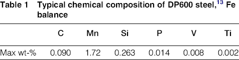
Typical chemical composition of DP600 steel, 13 Fe balance
Experiments
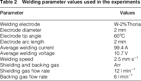
Welding parameter values used in the experiments
SH during welding was carried out using LINDOFLAMM®
14
short lance burners with a length of 240 mm and width of 27 mm. The burners consist of eight nozzles with an inter-distance of 30 mm. A mixture of acetylene and compressed air is applied. The burners are positioned parallel to the weld centre line and move with the same speed as the welding torch. The nozzles of burners were positioned 50 mm above the plates while the separation of burners varied from 177 to 367 mm. The welding torch to the burners distance varied from −220 mm (trailing) to +220 mm (leading). The maximum temperature at the underside surface of the plate was increased up to 520oC. The process parameters involved in welding with SH are shown schematically in Fig. 1.
A schematic drawing of the positional process parameters involved in welding with additional heat sources: burner separation (BB), burner distance to the weld centre line (BT) and burner distance to the plate (BP)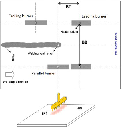
The temperature of the plates is measured using glass insulated k-type thermocouples with an accuracy of ±2.2oC, attached at the underside of the plate along a line perpendicular to the welding direction.
Residual stress profiles of conventionally welded plates and of plates welded with SH were measured at the Paul Scherrer Institute (PSI) by means of neutron diffraction. A time-of-flight Pulse OverLap Diffractometer was used to take advantage of the full neutron energy spectrum and beam intensity. 15 From the diffraction peaks the lattice spacing of ferrite (211) planes was obtained and used to calculate the longitudinal residual stresses. The stress free lattice spacing was obtained from a strip (2 × 2 × 280 mm3), which was electro-discharge machined from the middle of the plate perpendicular to the weld line from the plate edge to the weld zone.
The out-of-plane distortions of the plates before and after welding and welding with SH were measured by means of the DIC method with an accuracy of 50 µm. In order to make the comparison of the experiments simple and fast, a distortion index is defined based on the result of DIC measurements. The distortion index is the difference between the maximum and the minimum out-of-plane deformation of a plate.
The microstructure of the weld metal, the HAZ of the weld (HAZ-welding), the base metal and the heated area beneath the burners were studied at a cross section perpendicular to the weld and in the middle of the plate using Marder and Benscoter etchant. Hardness profiles were also taken across the welds, the HAZs and the heated areas beneath the additional heating burners, for different materials using Vickers micro-hardness measurements with an indentation load of 300 g.
Numerical approach
The numerical approach is based on a de-coupled thermo-metallurgical-mechanical finite element model developed for both conventional welding and SH using the commercial finite element code Msc-Marc.
There are three main fields in the model: the thermal, the microstructural and the mechanical fields. Since it was found that the models neglecting the effects of phase transformations on the stress and strain fields predict the final residual stress profile (and out-of-plane deformation) very close to the models including these effects and are in good agreement with the experimental results, 16 the microstructure field is not included in the models used in this study. Therefore, the simulations are in fact based on a thermo-mechanical model.
The thermal model includes the heat inputs of the welding process and the SH sources and the heat losses by convection, radiation and conduction. The welding heat source is modelled by the volumetric heat flux with Gaussian distribution.
17
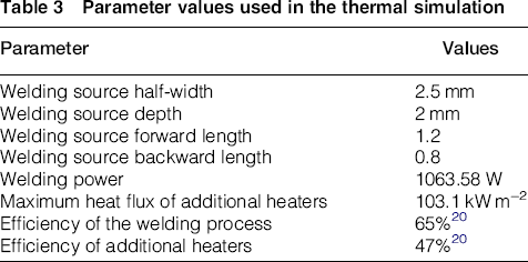
The burners of thermal tensioning are modelled by eight circular Gaussian heat flux distributions with an inter-distance of 30 mm. The parameters used in the thermal modelling are summarised in Table 3. The efficiency was calculated based on the temperature dependent thermal material properties are shown in Fig. 2
a.
13
Parameter values used in the thermal simulation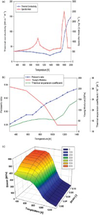
The mechanical analysis includes the modelling of the constraints by the clamping device and the plastic strain resetting at elevated temperatures because of melting. The clamps are modelled by applying spring links with a stiffness of 2 × 10⁷ N m−1 in the clamped conditions. The stiffness value was calculated based on the approach presented by van der Aa. 13 The stiffness is gradually reduced over 2 s during releasing of the clamps. The temperature dependent mechanical material properties are shown in Fig. 2 b and c. 18 An isotropic hardening model is used in the simulations. When the material reaches the solidius temperature, the plastic strains are set to zero. The solidius temperature of the DP steel, with the chemical composition mentioned in Table 1, is calculated to be 1760 K, using Thermocalc™.
The meshes used in the thermal and the mechanical analysis are based on shell elements shown in Fig. 3. The areas where the burners are applied are re-meshed using a node in a box criterion.
19
The mesh contains 10300 four node shell elements (Element 85
19
).
The mesh used in the simulation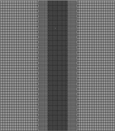
As stated before, the microstructure field is not implemented in the simulations. The mechanical material properties used in the simulations are all from tensile test measurements at elevated temperatures. In the weld zone and the HAZ the cooling rates are very high and result in non-equilibrium microstructures. The properties of these microstructures are not captured by the tensile test at elevated temperature. In the simulation results, it is expected that the main error and deviation sources are related to the material properties used.
Experimental results and discussion
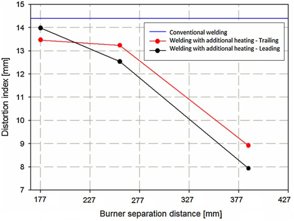
The effect of the burner induced temperature on the distortion index for DP600 plate is shown in Fig 4. By increasing the burner induced temperature, the distortion index of the plate is decreased first after which it increases. The case with experimentally obtained minimum distortion is obtained when the temperature at the underside of the plate is around 320°C. The results of the other process parameters on the distortion index are tested using this burner setting (temperature). Figure 5 shows the effect of burner separation distance on the distortion index after conventional welding and SH. It is seen that for both leading and trailing situations when the burner separation distance is increased the distortion index is reduced. The best position of the burners in this case is the area close to edge of the plate edge 193.5 mm from the weld centre line. Both the leading and the trailing situations can reduce welding distortion. However, the leading situation leads to less out-of-plane deformation.
The effect of the additional heating temperature at the underside of the plate on the distortion index The effect of the burner separation distance on the distortion index after conventional welding, and welding with 145 mm leading and trailing additional heating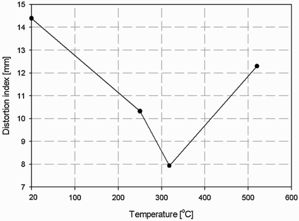
The effect of the position of the burners relative to the welding torch for a burner separation distance of 387 mm (leading and trailing) on the distortion index is shown in Fig. 6. The trend of distortion change here is non-linear. The experimentally obtained minimum distortion case is obtained, where the burners are located 193.5 mm from the weld centre line and 145 mm leading to the welding torch.
The effect of the burner distance to the welding torch on the distortion index after welding with additional heating. The burner separation is 387 mm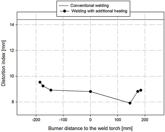
The result of the final out-of-plane deformation measurement after welding is compared to that of SH in the experimentally obtained minimum distortion case in Fig. 7. The out-of-plane deformation after welding with additional heating has been decreased significantly. Nevertheless, the plate is not flat. Angular deformation can be seen after welding with additional heating.
The final out-of-plane deformation of DP600 plate after a conventional welding and b SH for the case with experimentally obtained minimum deformation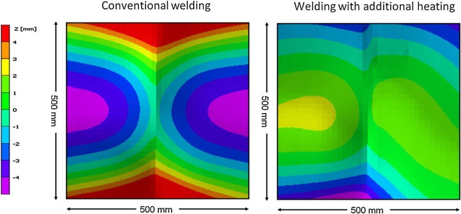
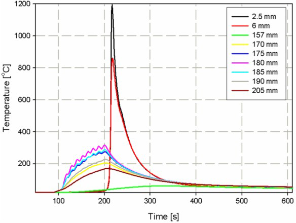
Figure 8 shows the temperature as a function of time at different positions from the weld centre line for conventional welding of DP600 while the temperature profile during SH for this plate is shown in Fig. 9. It is seen that the temperature of the positions located beneath the burners is increased significantly compared to that of conventional welding.
Temperature as a function of time for conventional welding of DP600 plates at several positions from the weld centre line Temperature measurements for SH at different positions from the weld centre line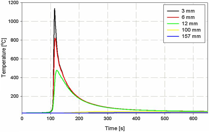
During welding of DP600, the base material that consists of martensite in a ferrite matrix, will transform to austenite when the temperature exceeds the A3-temperature. Depending on the cooling rate, the austenite transforms back into acicular products, bainite or martensite.
It was shown in the temperature measurement that the temperature profiles of the HAZ (of welding) and the weld zone for both conventional welding and SH are the same, i.e. the heat of the burner does not influence the weld. Therefore, the development of microstructure in these regions should be very similar. Figure 10 shows the micrographs of the weld, coarse-grained HAZ (of welding), fine-grained HAZ (of welding) and base metal of conventionally welded DP600 steel. The areas beneath the burners have a similar microstructure to the base metal (Fig 10
d).
Micrographs of the samples showing a close-up of the a weld metal, b coarse-grained HAZ (of welding), c fine-grained HAZ (of welding) and d base metal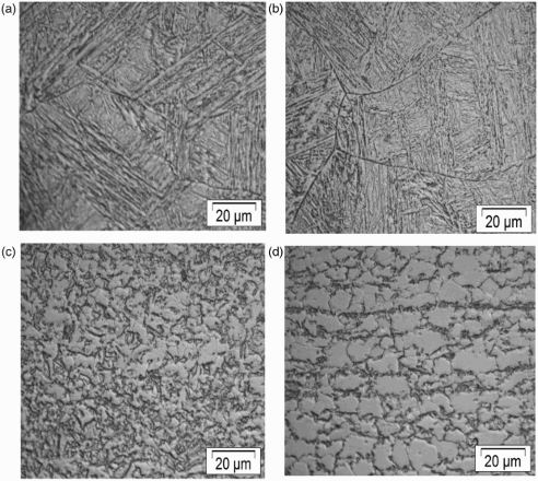
Figure 11 shows a SEM photograph of the base material and the heated area beneath the burners in SH experiments.
SEM display of a base metal and, b the area beneath the burner in SH experiments of DP600 plates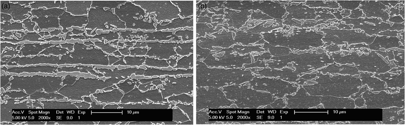
Hardness profiles were taken across the weld, the HAZ and the heated area beneath the additional heating burners. The locations of the measurements are shown in Fig. 12 and the hardness profiles are shown in Fig. 13.
The locations of hardness measurements of conventionally welded and welded with SH DP600 plates. The measurements were performed for a HAZ (of welding) and weld zones and b beneath the burners The hardness profile for a both conventional welding and SH and b the hardness profile in the side heated zones beneath the burners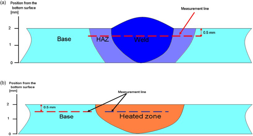
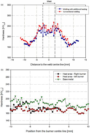
Figure 13 a shows the hardness profile for the weld, HAZ (of welding) and base metal regions. The base metal hardness was approximately 200 HV. The maximum hardness in the conventional weld was around 250 HV. The hardness level of the weld with SH is more or less the same as for the conventional weld. In both cases, softening zones can be seen further away from the weld. The results indicate that additional heating does not affect the hardness levels around the weld.
Figure 13 b shows the hardness profile of the heated area beneath the burners as a function of distance to the heating line. The figure includes the hardness of the base material. As can be seen from the figure, tempering of the martensite of the original base metal during additional heating, causes a reduction of hardness for the areas beneath the both burners.
The longitudinal residual stress distributions for conventionally welded DP600 plates and after welding with additional heating are shown in Fig. 14. The longitudinal residual stresses were measured for the weld with SH, the experimentally obtained minimum distortion. Figure 14
a shows the results of conventional welding while the results of welding with SH are shown in Fig. 14
b. In the both cases, the longitudinal residual stresses are measured after releasing the clamps. The releasing of the clamps took place when the temperature of the plate had reached room temperature.
Longitudinal residual stress measurement results for DP600 after a conventional welding and b SH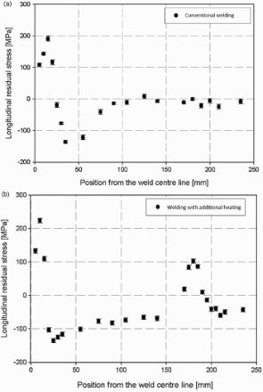
It is clear that SH induces tensile stresses underneath the burner positions. The maximum tensile stresses at the weld and HAZ (of welding) for the conventional weld and SH are more or less similar. The left most three points in Fig. 14 a and two points in Fig. 14 b demonstrate that the microstructure affects the tensile stresses. By approaching to the weld centre line, a drop can be seen in the residual stresses. This drop is attributed to the effects of solid phase transformations on the residual stresses in both cases. The maximum compressive stress for conventional welding occurs at a larger distance from the weld centre line compared to welding with additional heating. The level of the maximum compressive stresses is more or less similar for both processes. The area between the HAZ (of welding) and the heated area shows a significant difference in the stress levels.
Numerical predictions and discussions
The predicted temperature profile during conventional welding of DP600 at different positions from the weld centre line is shown in Fig. 15.
Predicted temperatures for conventional welding at the underside surface for different positions from the weld centre line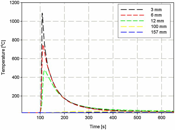
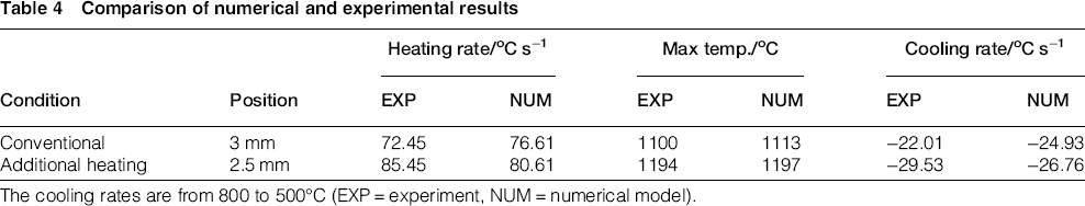
The prediction result of the temperature profile during SH is shown in Fig. 16. The eight peaks observed during the experiments cannot be modelled by the approach adopted in this study. However, the predictions are in a good agreement with the temperature measurements. The maximum temperature, the heating and the cooling rates are all very close to the measurements as shown in Table 4 for a point as an example.
Temperature prediction results for welding with additional heating at different positions from the weld centre line. The temperature cycles are shown for the underside surface Comparison of numerical and experimental results The cooling rates are from 800 to 500°C (EXP = experiment, NUM = numerical model).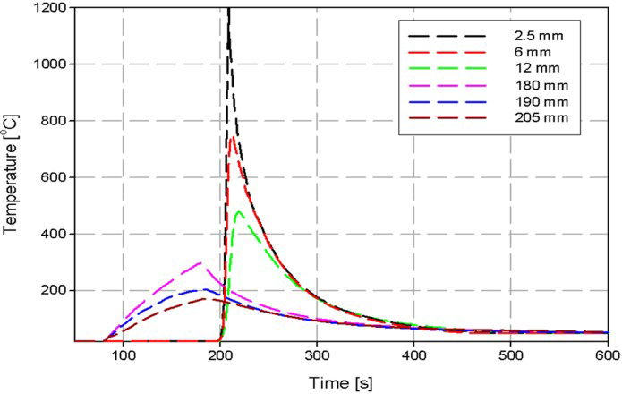
The effects of solid phase transformations on the maximum out-of-plane deformation were predicted to be around 9%. 16 However, these deviations can be adjusted by using different spring stiffnesses. The risk of computational instability and divergence is very high when phase transformation is implemented. For such reasons, solid phase transformations were excluded in all simulation tasks.
Figure 17 shows the predicted final out-of-plane distortion of DP600 after conventional welding and SH for the experimentally obtained minimum distortion case. A distortion scan over the cross section of the middle plate is presented in Fig. 18. The results are shown in Fig. 18
a for conventional welding and Fig. 18
b for SH. In both numerical results and measurement, the distortion reduction after welding with additional heating can be seen. The prediction results are close to the measurements for conventional welding. However, there is a deviation between the measurements and the predictions for the welds with additional heating. In welding with additional heating, two heaters are used and therefore the effects of uncertainties such as material properties at high temperature and clamping behaviour (and pressure) on the final deformation are more significant than for conventional welding. It should be mentioned here that the room temperature releasing of clamps are different in practice compared to that in the numerical model. The clamps are released manually in practice. In the modelling activities, they are released all at once in both conventional welding and welding with additional heating. Moreover, in conventional welding (one heat source) the two clamps close to the welds can have a big influence on distortion but in welding with additional heating (three heat sources) all four clamps and their releasing manner can influence final distortion of the plate.
The predicted final out-of-plane deformation of DP600 steel plate after a conventional welding and b welding with SH in the experimentally obtained minimum distortion. The scale is −8 to +8 mm Comparison between the predicted and measured out-of-plane deformation for points located at the middle part of a DP600 plate from one edge to the other edge along a line perpendicular to the weld centre line for a conventional welding and b welding with SH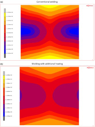

Figure 19 shows a comparison between the prediction and the measured results of longitudinal residual stresses for DP600. Similar trends to the experiments are found in the numerical calculations. There is good agreement between the modelled and the experimental results. The model, however, excludes the effects of phase transformations.
Comparison between the modelled and the measured longitudinal residual stress results after a conventional welding and b welding with SH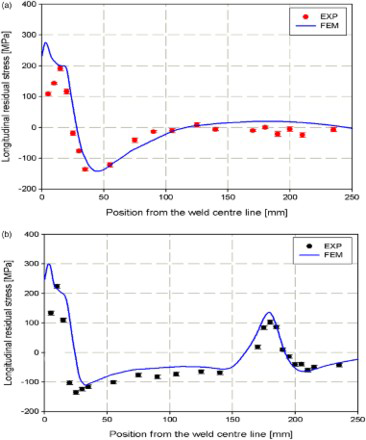
The stress development during conventional welding is compared to that when welding with additional heating. In this comparison, three different burner positions (leading, trailing and parallel situations) are considered. The longitudinal stress development in the line in the middle of the plate is displayed for four time steps as shown in Fig. 20. These time steps represent when (a) the welding torch has not yet reached the middle line of the plate, (b) the welding torch is positioned at the middle line, (c) the welding torch has passed the middle line and (d) the final residual stress profile when the workpiece has reached room temperature, but is still clamped.
The predicted stress development during conventional welding and welding with SH with different burner positions for three time steps when a the welding torch has not yet reached the middle line of the plate, b the welding torch reaches the middle line, c the welding torch has passed the middle line and d the final residual stress at room temperature in the clamped condition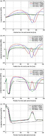
Figure 20 a shows a situation in which the welding torch has not reached the middle line. As can be seen, for the conventional weld and the welding with burners in the trailing configuration, the weld line is under compressive stresses and the stress state for the positions located at or near the plate edge is negligible. This means that the material in front of the welding heat source already experiences the effects of the advancing arc. The material directly surrounding the arc will try to expand resulting in compressive stresses in these areas.
In the parallel configuration, the welding torch has not reached the middle line while the burners are already passing this line, because the burners have a length of 240 mm. Again compressive stresses are introduced underneath the position of the burners as the expansion is counteracted by the surrounding materials. These compressive stresses induce tensile stresses in the areas around the heated zone.
In the leading configuration, the burner has passed the middle line completely and therefore the heated area already cools and the compressive stresses present in this area begin to decrease.
Figure 20 b shows the situation in which the welding torch has reached the middle line. Since the material is melting at the weld centre line in all cases, the stress state is zero for the points up to a distance of 2.5 mm from the centre line (i.e. the fusion line). Owing to the high temperatures near the FZ, the points located close the weld zone experience high compressive stresses. These compressive stresses are balanced by tensile stresses outside the HAZ (of welding) for conventional welding. In the case of trailing heating, the effects of the additional heat sources are now experienced by the material. In the leading case, the points at the position of the burner are cooled even further and a transition from compressive to tensile stresses has taken place.
Figure 20 c shows the situation in which the welding torch has passed the middle line. The temperature of the weld zone is reducing and therefore the compressive stresses at the weld centre line change to tensile stresses. For the area where the burner is located, the temperature is also reducing for the leading and the parallel case while for the trailing case the burner is still heating. Figure 20 d shows the stress profile when the plate is at room temperature in the clamped condition. Tensile stresses are formed in all cases in the weld and the HAZ (of welding). Near the edges of the plate, tensile stresses are formed when welding with additional heating, while the stresses in this area are compressive for conventional welding. At the edges of the plate, compressive stresses are formed in welding with additional heating. In this area, compressive stresses are formed for conventional welding with higher absolute values.
SH does not reduce the compressive stresses ahead of the weld zone, nor does it increase the tensile stress in the weld zone during cooling. The positions of the burners are far from the weld zone and thermal influences hardly change the stress state in this zone during heating or cooling. The tensile stresses generated by the burners at or near the plate edges redistribute the final residual stresses upon release of the clamps.
Conclusions
SH can successfully reduce out-of-plane deformation. The plate with experimentally obtained minimum distortion after SH was obtained for D600 when the burners are located 193.5 mm from the welding centre line and 145 mm leading the welding torch. The burner induced temperature was around 320°C. It was found that the closer the burners were to the weld centre line the higher deformation is obtained. Moreover, the trend in distortion as a function of the distance between the burner and the welding torch was non-linear. It was seen that the temperature field around the welds is not changed by additional heaters when the temperature of conventionally welded plates is compared to that of SH with experimentally obtained minimum distortion. In the temperature profile of SH, eight peaks for the points beneath the burners were observed. It was found that the microstructure of the weld and the HAZ (of welding) in conventional welding is the same as the weld with SH. The areas beneath the burners in DP600 show a lower micro-hardness than the base metal, mainly because of tempering the martensite. The maximum tensile stresses at the weld and HAZ (of welding) for conventional weld and weld with SH were similar and there was a peak of tensile stress for the area beneath the burner. In order to investigate the influence of SH during welding on the thermal, the microstructural and the mechanical fields, 2D finite element models were constructed and extended. The predicted residual stresses are close to the measured values for both conventionally welded plates and plates after SH. The characteristic of SH from a numerical point of view is the creation of tensile residual stresses at the location of the burners. The stress development profiles and the final residual stresses in conventional welding and welding with SH indicate that (from numerical model), welding with SH does not reduce the compressive stresses ahead of the weld zone, nor does it increase the tensile stress in the weld zone during cooling. The tensile stresses generated by the burners redistribute the final residual stresses.