
Abstract
CuCrZr alloy (Cu-0.8wt-%Cr-0.1wt-%Zr) and 316L stainless steel (Fe-0.03wt-%C-16wt-%Cr-10wt-%Ni) plates were successfully friction stir lap welded resulting in significant mechanical mixing of the two matrix elements, Cu and Fe, in the stir zone. The severe mixing not only led to improved load bearing response but also leads to form Cu-rich and Fe-rich regions in the weld nugget. The formation of these phases governs the failure mechanism of the joint. Tensile properties of the weld showed promising response when compared with joints made for the similar alloy pair by other welding techniques. This suggests strong feasibility of applying FSW for joining Cu and steel for nuclear applications.
Introduction
Welding of dissimilar materials is of great importance to specific industries such as automobile, nuclear and aerospace where the mutual presence of certain properties is necessary for a particular application [1]. Researchers have worked in joining a variety of dissimilar material combinations by either fusion welding or by solid state welding such as friction stir welding (FSW). Among them, Cu-Steel joint has direct application in nuclear industry where CuCrZr alloy is bonded with stainless steel (SS 316L) as a first facing wall of plasma fusion reactor [2, 3]. This is because the CuCrZr alloy being a strong thermal conductor is used as a heat sink whereas SS 316L serves the purpose of structural integrity and protection from corrosion. Further, very limited attempts have been made to join this pair of which only a few tried solid state welding techniques such as hot isostatic pressure (HIP) [4-6], explosive [7, 8] and diffusion bonding [9, 10]. Various researchers explored the feasibility of HIP joining of CuCrZr/SS 316L and investigated the metallurgical quality of weld and effect of various parameters to optimise the joint strength [4-6]. The quality of CuCrZr/SS 316L joint also improved by nickel electroplating on CuCrZr and SS 316L. Researchers also investigated microstructural and mechanical properties for dissimilar material joints for the first wall of fusion reactor by explosive welding [7, 11]. Singh et al. [10] performed the diffusion bonding of dissimilar welding of CuCrZr/SS 316L and optimised the process parameters with and without nickel interface layer. They observed shear strength to be more with nickel interlayer as compared to without interface layer. Nickel (Ni) interlayer enhances the diffusivity for diffusion bonded samples of base materials CuCrZr and SS 316L. Nickel interlayer also improves wettability and enhances diffusion at both parent materials at the lower temperature regime.
This work for the first time attempts to join CuCrZr alloy with SS316L stainless steel using FSW. The evolution of weld microstructure during FSW is correlated with its mechanical properties and resultant fracture behaviour.
Experimental procedure
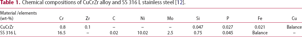
Chemical compositions of CuCrZr alloy and SS 316 L stainless steel [12].
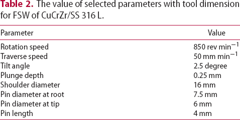
The value of selected parameters with tool dimension for FSW of CuCrZr/SS 316 L.
Results and discussion
Figure 1(a,b) shows the optical images for as-received CuCrZr (grain size number = 4.8 and hardness = 94 HV) and SS 316L (grain size number = 6.2, hardness = 177 HV) alloys, respectively, showing the equiaxed grains in the both of these materials. Further, Figure 1(c) depicts the CuCrZr and SS 316L weld along transverse cross-section featuring the nugget zone profile, highlighting the mixing of copper and iron at the weld interface. The joining was performed by keeping steel over copper such that plunging through steel would result in the fluent plasticisation of both steel and copper for easy flowing and mixing at the weld junction. In case, plunging was done in Cu, higher heat input would have been required to plasticise bottom steel. This higher heat input may, however, cause weakening of Cu since, it is already well investigated that Cu alloys get weaker after FSW due to abnormal grain growth [13].
Optical microstructure of (a) CuCrZr alloy, (b) 316L stainless steel, (c) Transverse cross section of CuCrZr alloy and SS 316L dissimilar weld, (d) backscattered electron image showing mixing of iron and copper at weld interface, (e) EDS-elemental mapping displaying Fe and Cu-rich region in the weld for image, (f) the magnified backscattered electron image for mixing of copper and iron and (g) EDS-elemental mapping for flow of iron and copper for (f) image.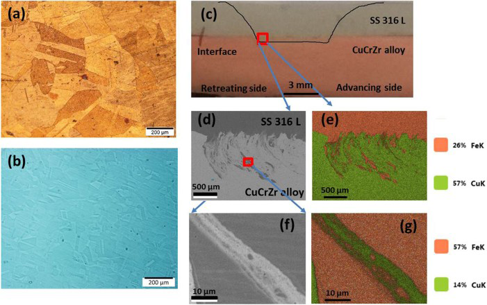
Figure 1(d,e) shows severe mechanical mixing of steel with copper thereby forming a strong interlocking structure in the weld cross section. The distribution of iron was observed around up to 1 mm towards copper from the interface. The elemental distribution of Cu and Fe occurs over the mixed region. Further, Cu and Fe are immiscible and thus it is interesting to investigate the microstructural evolution as a result of FSW which involves severe plastic deformation. Also, shear driven elemental transport during FSP results in phase evolution away from equilibrium phase diagram and thus may result in unexpected microstructure in the nugget region during welding [14]. This is further confirmed by performing microstructural investigation of the mixed region at high magnification (Figure 1(f,g)). The mixing occurs at micron level due to typical nature of the FSW process in which each grain exhibits different levels of straining and temperature gradients [15].
Figure 2(a) shows the load vs. extension curves for three lap shear samples showing the average peak load of ∼19 KN and an extension of around 1.2 mm upon complete failure via weld debonding under shear. The hardness of the welded region (Figure 2(b)) comes out to be lower than SS steel but greater than CuCrZr alloy which is also an indication of the fact that there is substantial mixing at the nugget.
(a) Load-extension curve for three samples at constant strain rate. (b) Hardness profile across the interface at three different levels (middle, left and right) and (c) micro image of the weld interface to indicate the measurement of hardness taken along three different lines.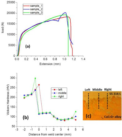
Figure 3(a) shows fractured sample with lap shear testing and depicts failure occurred by weld debonding under shear load. The joint strength is significantly higher than the diffusion bonding [9, 10]. The microstructural characterisation of the fractured surface was done by SEM-EDS to understand the mode of failure and distribution of iron and copper at the fractured surface. Figure 3(b,c) shows the secondary electron image and its corresponding elemental mapping displaying presence of iron and copper at fractured surface. It also gives clear evidence of material (steel) flow from the retreating side (RS) to advancing side (AS) behind the tool pin during process. The majority of Fe-rich region is observed towards retreating side which got transitioned along advancing side behind the tool under flowing action. Detail investigation of the fracture surface with EDS reveals two distinct regions namely Cu-rich (towards AS) and Fe-rich (towards RS), respectively.
(a) Fractured sample of CuCrZr alloy and SS 316 L dissimilar weld, (b) SEM secondary electron image of fracture surface, (c) EDS-elemental mapping at fracture surface, (d) localised dimples at Cu-rich region, (e) small dimples with crack at Fe-rich region and (f) average chemical composition at crack.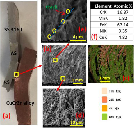
It was apparent from the high-resolution imaging that Cu-rich region shows the formation of small dimples (Figure 3(d)) whereas Fe-rich region show formation of cracks along with dimples (Figure 3(e)). The average chemical composition of elements is also mentioned for various locations on the crack line (Figure 3(f)) to verify the iron enrichment of region. In short, the mechanical interlocking could withstand the load up to a certain extent beyond which the separation starts at the Fe-rich region owing to stress concentration arising at the weld interface due to hardness mismatch and ultimately results in the weld debonding.
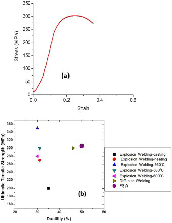
Figure 4(a) displays the tensile behaviour of the weld thereby highlighting the ultimate tensile strength of 305 MPa. This value of the load bearing ability in both the loading modes was found to be significantly high in comparison with the values reported in the literature for the joining of this pair with other welding routes [5, 8-10]. Figure 4(b) shows that the strength and ductility for the CuCrZr and SS 316L joint (violet colour circle mark in Figure 4(b)) obtained via FSW is reasonably good as compared to the joints obtained via other processes [5, 8, 9]. FSW shows improvement in the joint strength and ductility due to the formation of a strong mechanical interlocking of both Cu and Fe without undergoing local melting and solidification. This improved joining ability is attributed to the typical characteristic of FSW as against the arc welding processes. Any arc welding process involves melting and solidification at the welding interface, the resultant microstructure of the weld shows dendritic morphology as against a very fine-grained homogeneous microstructure in FSW. This refined and homogenised microstructure of the FSW welding nugget provides it with better strength under loading. Further, compared with advanced welding techniques like a laser beam or electron beam welding, FSW microstructures are more uniform and can be attained in the much cheaper way. Thus, as various welding routes have been implemented in attaining CuCrZr joining with stainless steel, FSW outperforms all of them in terms of showing better combination of strength and ductility.
Conclusions
This work for the first time reports the successful joining of the industrially important CuCrZr alloy with stainless steel (SS 316L) using FSW process. Higher load bearing ability was obtained for the joint owing to strong mechanical interlocking feature developed along the weld cross section, also suggesting good mechanical bonding tendency between Cu and Fe. Further, the joint can be made even better by tailoring the FSW parameters such that the mechanical interlocking can be enhanced by the formation of pronounced hooking at the steel/Cu alloy interface. The joint property can be optimised by modifying FSW parameters such as rotation speed, traverse speed, and tool geometry by improving material flow and heat transfer to improve the weld strength. The variation in these parameters would lead to optimisation of the weld and this can be done in future.
Footnotes
Acknowledgments
Authors would like to thank Centre for Advanced Research and Technology (CART) for providing access to the micros-copy facilities at the University of North Texas, USA.
Disclosure statement
No potential conflict of interest was reported by the authors.