
Abstract
Friction stir welding (FSW) has proven to be a viable technique for joining a wide variety of alloys. However, thick section welding of alpha and near-alpha Ti alloys has proven particularly challenging. Previous research at the Naval Research Laboratory using Ni markers in CP Ti friction stir welds indicated that elemental additions of Ni to the joint line can provide substantial benefits for improved weldability of these alloys. The current study surveys the effects of Ni and other elemental additions to CP Ti friction stir welds to determine their influence on the resultant weld microstructure, weld surface finish, and welding machine forces. These results reveal that Ni provides the most benefits for the concentrations examined, but other elements may also provide benefits at lower concentrations. The addition of these elements may improve the weldability and weld quality for FSW of CP Ti, enabling thick section welding of this and similar alloys.
Introduction
Friction stir welding (FSW) is a solid-state joining process invented in 1991 [1]. During this process, a rotating, non-consumable tool is plunged into the material to be joined, where it heats the surrounding material through frictional and deformation heating. This heat reduces the flow stress in the surrounding material, allowing the tool to ‘stir’ that material. As the rotating tool is translated along the joint line, it transfers the stirred material around the tool to be deposited in its wake to form the weld [1, 2].
As a solid-state process, FSW avoids many of the issues associated with conventional fusion welding. It reduces or even eliminates solidification problems common in many alloys and can thus be applied to a much broader range of materials, including many that are viewed as ‘unweldable.’ In addition, the FSW process is highly automated, enabling the consistent fabrication of defect-free welds with good properties once the appropriate welding conditions are determined.
FSW was initially developed for aluminium alloys because of their low melting point coupled with a high thermal conductivity, and thus ready access to reduced flow stresses. It has since been developed for a wide range of materials including high strength steels and Ti alloys. However, thick section alpha and near-alpha Ti alloys present a particularly difficult challenge for FSW; no stable FSW conditions have been found that consistently achieve defect-free welds in thick (≥10 mm) sections of these alloys [3-7]. This limited weldability of thick section alpha and near-alpha Ti alloys arises from the poor heat transfer through the weld thickness via either conduction or convection because of the combined constraints of thermal conductivity, flow stress and its temperature dependence, heat capacity, and available tool materials (which limit the potential tool features) [7-9].
The weldability of thick section alpha and near-alpha Ti alloys can be improved either through the introduction of heat via a secondary heat source [10] or by other modifications of the material flow properties at the joint line. The FSW process for these alloys has been modified to include a variety of secondary (or alternative) heat sources including laser [11], induction heating [7, 12], electrical [13], and ultrasonic [14] to evolve into what has become known as Thermal Stir Welding. One of these processes may yet prove successful for the thick section welding of these alloys.
Very little work has been performed to investigate other methods to modify the material flow properties along the joint line. The most promising to date for alpha Ti alloys was discovered serendipitously during research investigating the use of Ni foil placed at the joint line and used as a tracer element to reveal the material flow during FSW of commercial purity titanium (CP-Ti) [5-6]. During this study, it was noted that the presence of the Ni foil significantly reduced the weld loads, improved the surface finish, and eliminated the formation of voids, while maintaining mechanical properties comparable to those typical of Grade 2 CP-Ti. The current study was initiated to investigate the effect of Ni and other elements on the FS weldability of CP-Ti, and thus their potential for enabling thick section FSW of this alloy.
Materials and methods
The friction stir welds examined in this study were prepared on the MTS FSW process development system at the University of South Carolina by welding two 152 × 305 mm (6′′ × 12′′) plates of 6.35 mm (0.25′′) thick commercial purity (CP) Ti. A simple W-La tool with a 19 mm diameter shoulder with 5.87° concavity and a 5.6-mm-long pin that tapered from 9.8 to 8 mm diameter was used to fabricate each weld under Z position control and argon shielding gas with a 100 rev min−1 tool rotation rate and 25 mm/min weld speed. The actual tool position was adjusted manually as necessary to maintain its position along the joint line. No tool debris or other defects were observed in any of the welds. Twelve welds containing two 75 × 6.3 mm sections of approximately 100-µm-thick elemental foils of high purity Al, Co, Cu, Fe, Mo, Nb, Ni, Pb, Ta, V, Zn, or W at the joint line were fabricated according to the plan shown in Figure 1. Multiple foils were used in some cases to achieve the 75 mm foil length.
Images of the top surface of each weld with approximate location of the elemental foils indicated, and corresponding profilometry traces of the height variations along the weld centreline (height scale bar is 1 mm), showing the effect of the presence/absence of elemental foils on the surface structure (foil locations are approximate).
The top surface of each weld was imaged by optical microscopy and the surface roughness was characterised by profilometry on a Stil Optical Pen White Light Profiler. The samples were also sectioned to obtain both a 6-mm-wide transverse cross section across the first foil-containing region and a longitudinal cross section along the weld centreline of the second foil-containing region. The transverse cross sections were imaged by optical microscopy and by X-ray computed microtomography (XCMT) on a Zeiss Versa 520 with an 8.5 µm resolution. The longitudinal cross sections were imaged by optical microscopy, scanning electron microscopy (SEM), and energy dispersive spectroscopy (EDS).
Results and discussion
The 12 welds fabricated for this study exhibited a variation in surface roughness and features, both between different welds and often across the same weld (Figure 1). Most of the welds behave similarly, with quasi-periodic variations in the height (and also welding force) that are much coarser than the advance per revolution. The quasi-periodic roughness variations are replaced by a fine-scale surface roughness in the Cu and Mo welds, with roughness amplitudes greater than (for Ti-Cu) and less than (for Ti-Mo) the typical quasi-periodic features. However, the most notable behaviour was exhibited by the Ti-Ni weld, which has a dramatically reduced surface relief and an absence of the quasi-periodic variations across the foil-containing regions (and a similar reduction in welding forces through those regions), illustrating some of the benefits reported by Everett et al. [5, 6]. It is important to note that a number of other welds (particularly, those containing Co, Cu, Nb, Ta, or V) exhibit a similar smoothing localised at the end of the foil-containing region, where the welding tool transitions to a region without the foil. The decrease in elemental foil content at these transitional regions where the smoothing is observed indicates that these elements may provide a substantial improvement in weldability (including both surface roughness and welding forces) if used in smaller concentrations (e.g. with a thinner foil insert).
The peak welding temperature was measured at two thermocouples placed near the centre of the W weld to be 831 and 836°C, which are within 80°C of the beta transus temperature of CP Ti [15]. Similar peak temperatures are expected for all of the welds, although the actual values may be higher because the tool pin disturbed the thermocouples during welding. There was no evidence of elemental foil deposits within the welds fabricated with Al and Pb foils, the two lowest melting temperature elements. Instead, the foil material was present as a thin deposit on the back surface, indicating that these foils (with melting temperatures of 327 and 660°C for Pb and Al, respectively) melted as they were exposed to the welding temperatures and then extruded from the joint line onto the back of the weld plate. In the Ti-Cu weld, which contains the next lowest melting temperature foil, a continuous deposit of Cu was present along the weld flash (indicated in Figure 1) due to extrusion during welding. SEM imaging demonstrated that some Cu remained inside the weld, although it was not observable by XCMT.
Optical microscopy of the weld longitudinal cross sections reveals a variation in the elemental foil distributions, as shown in Figure 2. Many of the welds contain discrete foil fragments aligned with what appears to be the trace of the inclined three-dimensional effective shear surface produced by the tapered tool [16-18]. The tool profile and presumed effective shear surface behind the tool are indicated in Figure 2. Discrete fragments of the foils are evident in the welds containing W, Mo, and Ni. The Ti-W weld displays large foil remnants oriented nearly horizontally near the base of the weld and aligned with the 3D shear surface elsewhere. The Ti-Mo weld contains smaller fragments, and the Ti-Ni weld contains even smaller foil fragments, aligned similarly. In both of these welds, the foil remnants appear to be located mostly towards the base of the weld, although some are also visible in the upper half of the weld. The Ti-Cu and Ti-Fe welds appear very similar to each other and exhibit both small, isolated foil fragments towards the top of the weld and elongated, fine features through the rest of the weld arising from the elemental foils. The welds containing Co, Zr, V, and Nb do not show discrete foil fragments; instead, these foil deposits appear as continuous, quasi-periodic features with a repeat distance about 10–15 times larger than the tool advance per revolution. The foil remnants in these welds have a complex structure near the top and base of the weld, but appear as thin sheets that converge and then diverge again through most of the thickness of the weld (see Figure 2). This behaviour may arise from different stick/slip conditions through the thickness of the weld caused by a through-thickness variation in temperature. No features were evident on the polished surfaces of welds containing Al, Pb, or Ta due to extrusion of the foils during welding (for Pb and Al) or similar etching behaviour (for Ta).
Optical micrographs of the elemental foil distributions after FSW as observed on the longitudinal cross section and top surface. The tool dimensions and estimated shape of the effective shear surface in the wake of the tool are indicated in the Ti-Al image.
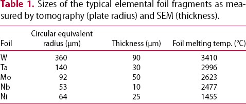
More detailed analysis was conducted by X-ray tomography (Figure 3) and SEM (Figure 4). Tomography of the Al, Cu, Pb, and V welds is not shown because the foils of the first three were largely extruded out of the joint line during the welding process and the V foil does not have sufficient contrast relative to the Ti matrix. These analyses revealed that, during welding, the foils were either fragmented into discrete, two-dimensional flakes (in welds made with W, Ta, Mo, Nb, or Ni foils) or stretched into thin sheets (for the V, Zr, Co, Cu, or Fe foils). Typical radius and thickness of the fragmented foil flakes are reported in Table 1. These demonstrate a strong correlation between the fragmentation/deformation of a foil and the foil melting temperature, suggesting that the foil strength at the welding temperature is a significant factor in the fragmentation behaviour. The highest melting point foils were fragmented into large (W), medium (Ta and Mo), or small (Nb and Ni) flakes and deposited along the apparent 3D shear surfaces. Nearly all of the foils experienced significant thinning during welding, but the W foil fragments remained relatively undeformed. The fine fragments of the Ni (and to a lesser degree, Mo) foil were distributed much more homogeneously through the weld than any of the other foils. Alternatively, the lower melting temperature foils (V, Zr, Co, Cu, and Fe) were stretched from their original 100 µm thickness and buckled during welding into continuous, thin (<10 µm) sheets. The top view of the Ti-Co weld (Figure 3) illustrates the typical distribution of these foils within the weld, exhibiting a quasi-periodic banding of the foil deposits. Note that the resolution of the tomography scans causes the thin Co foils to appear as fine fragments and cannot resolve the smallest fragments evident in Figure 2 (particularly the fine fragments in the lower half of the Ti-Ni weld). It is interesting to note that the foil remnant at the base of the Ti-Co weld indicates that the material flow occasionally occurs in the opposite direction, although this observation cannot be explained at this time.
X-ray tomography of the foil distributions within the Ti-X friction stir welds as viewed along the welding direction and (for Co, bottom right) from the top of the weld. SEM longitudinal cross section images of the post-weld elemental foil distributions near the weld mid-thickness in the welds containing W, Mo, Nb, Ni, Co, and Fe foils. Some solid solution reaction zones around the foil fragments are indicated for the Ti-Co and Ti-Fe welds. Sizes of the typical elemental foil fragments as measured by tomography (plate radius) and SEM (thickness).
The reactivities of the elemental foils with the CP Ti baseplate material were analysed by backscattered SEM imaging, EDS, and X-ray diffraction. No chemical reactivity was detected between the fragments of the highest melting point foils (W, Ta, and Mo) and the Ti matrix by EDS. The next highest melting point foil, Nb, contained nearly 10 wt-% Ti. The foils of the remaining two refractory metals (V and Zr) contained extensive amounts of Ti (∼50 and ∼40 wt-%, respectively). Foils in the Ti-Fe and Ti-Co welds were similarly deformed and enriched in Ti (22 and 8 wt-%, respectively). These foils were surrounded by a reaction zone that is visible in Figure 4 and identified by EDS as a solid solution within the Ti matrix. The intermetallic FeTi and Co3Ti phases were also observed by XRD. Similarly, diffusion of the matrix into the foils and vice versa caused Ni3Ti to form within the larger foil fragments and a Ti(Ni) solid solution to form around the highly refined fragments. The larger foil fragments were enriched to ∼2 wt-% Ti but the surrounding matrix contained only ∼0.7 wt-% Ni, as compared to the 2–7 wt-% Ni reported by Everett et al. [5-6], presumably reflecting the difference in welding conditions. Nevertheless, Everett et al. [5-6] demonstrated that mechanical properties were not substantially affected by any intermetallics than did form.
The location of the quasi-periodic foil distributions within the welds often parallels the presence of coarse features on the weld top surface and correlates to variations in the welding forces. In the Ti-Co weld (Figure 5), the coarse, quasi-periodic surface ridges (arrowed) are located where the foil features intersect the top surface. In addition, the surface features correspond to observed variations in spindle torque and machine forces along the X (welding) and Z (downward) directions. The correspondence between the surface features and welding forces is apparent across the entire weld (including both the foil-containing regions and the foil-free regions between them) in all of the welds examined in this study. Similarly, the correlation between the foil features and the surface ridges is obvious in the welds with Co, Zr, V, and Nb (see Figure 2), can be observed in the Ti-Ta weld by tomography, and also appears to occur in the Ti-W weld. Furthermore, there are also indications of this correlation in the Ti-Fe and Ti-Cu welds, although both the surface ridges and the quasi-periodic banding of foil features are much less prominent. While the TiAl and Ti-Pb welds show minor indications of such features, the lack of contrast from the foil remnants in these welds prevents a similar analysis. However, such a correlation is not evident in the Ti-Mo and Ti-Ni welds. Both of these welds exhibit a fine periodicity of surface features and foil remnants corresponding to the tool advance per revolution, but do not show the coarser quasi-periodicity in either foil distribution or surface features that is exhibited by the other welds.
Graphs of the surface height and measured machine forces with the corresponding optical montage along the weld direction of the Ti-Co weld, showing correlations between peaks in the coarse quasi-periodic surface features, the welding forces, and the intersection of the Co foil remnants with the weld surface.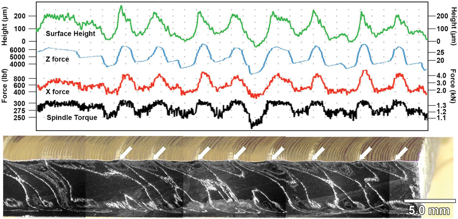
These correlations demonstrate that the quasi-periodic elemental foil deposits are associated with simultaneous increases in surface height, torque, X force, and Z force during welding. The seemingly more abrupt increase in sample height relative to the force variations is an artefact of the inclination of the effective shear surface and does not correspond to a difference in behaviour. These quasi-periodic variations are consistent with a cyclic variation between sticking and slipping welding conditions. Fabrication of good quality FS welds requires the maintenance of similar welding conditions through the thickness of the weld. In addition, available tool materials for FSW Ti limits the tool geometries to simple shapes that do not promote significant vertical mixing, and the poor thermal conductivity of Ti inhibits the heat flow from the tool pin and shoulder into the surrounding material, leading to greater radial and through-thickness thermal gradients. Because of this, tools for welding Ti typically have a small shoulder and tapered pin to balance the welding conditions at the top and base of the weld, relying more on heat generated by the tool pin while limiting heat generation by the shoulder that cannot be efficiently transferred to the base of the weld. The welding is normally performed near the beta transus temperature, although welding in this temperature regime can become unstable due to the rapid variation in the flow stress with temperature [9]. Flow behaviour can alternate between colder ‘sticking’ conditions below the beta transus that are more efficient at generating and transferring heat to the surrounding material, albeit with higher welding forces, and hotter ‘slipping’ conditions above the beta transus that have low machine forces but do not generate or transfer heat as well. The shear modulus of the elemental foils is well above that of the Ti matrix, particularly at the welding temperature (see e.g. references [9] and [19-21), resulting in flow of the Ti matrix around the foil during the hotter ‘slipping’ conditions alternating with the combined flow of the foil and matrix together during the colder ‘sticking’ conditions. This causes the variations in foil distributions, surface features, and machine forces observed in these welds. Such thermal variations are also likely the cause of the limited weldability exhibited by thick section alpha and near-alpha Ti alloys [3, 4, 7].
The differences in surface roughness and welding forces between the foil-containing and foil-free regions are shown in Figure 6. This compilation demonstrates that most elements have a neutral or adverse effect on the weldability of CP-Ti; Ni is the only foil that provides a dramatically reduced surface roughness with reduced welding forces, although Co and Fe appear to provide some benefits. Adding Ni to the joint line (1) reduces the surface roughness by more than 50%, (2) reduces the X force by nearly 20%, (3) reduces the Z force by nearly 10% with almost an order of magnitude less variation, and (4) does not substantially affect the welding torque.
Graphs of the surface roughness (standard deviation of surface height) and machine forces in the X-direction (welding direction), Z-direction (downward force) and spindle torque, with the standard deviations indicated, comparing the foil-containing and foil-free regions in each weld.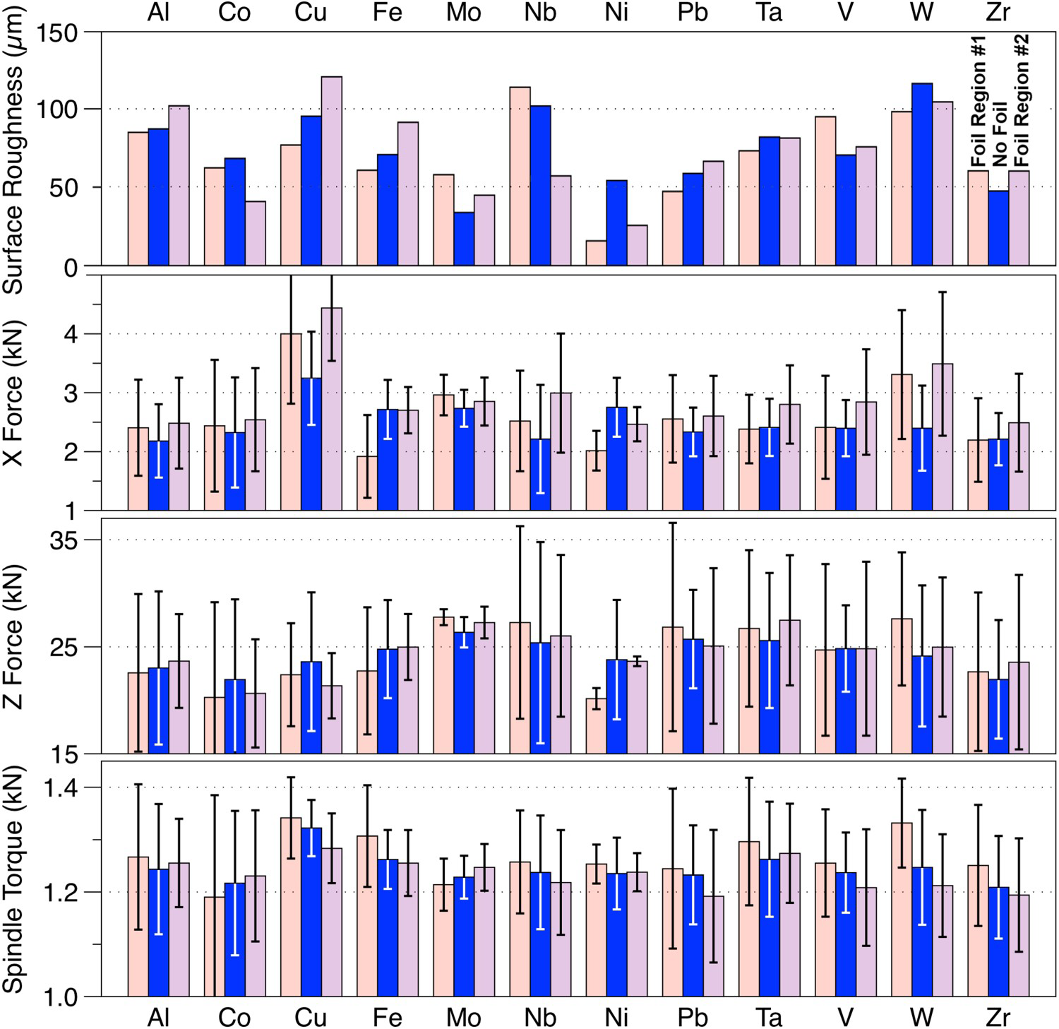
Conclusions
This study examined the effects of different elemental foils placed at the joint line to improve the weldability of thick section CP Ti friction stir welds. The foil remnants in most welds exhibited a quasi-periodicity, likely from a periodic variation in stick/slip condition, and fragmentation and deformation of the foils correlates well with the foil melting temperature. Welds containing Co, Cu, Nb, Ta, or V foils exhibited benefits at the transitions from foil-containing to foil-free regions, indicating that these elements may be more effective at lower concentrations (e.g. with thinner foils). And while Co and Fe foils appeared to also offer benefits for improved surface quality and reduced welding forces, this study demonstrates that Ni foils have the most promise of all the elements examined here for improving the weldability of thick section CP Ti.
Footnotes
Acknowledgements
The authors are grateful for the helpful discussions and assistance by Dr David Rowenhorst. We would like to acknowledge the funding provided by the U.S. Naval Research Laboratory under the auspices of the Office of Naval Research to support this research. In addition, we would like to express our thanks to Dr Wei Tang and Dr Anthony Reynolds of the University of South Carolina for their help in fabricating these welds.
Disclosure statement
No potential conflict of interest was reported by the authors.