
Abstract
Microstructure and mechanical properties of laser solid formed 30Cr–Mn–Si–Ni–2A steel are investigated. The deposits consist of epitaxial columnar grains, equiaxed grains or direction changed dendrites can be observed in the bulk specimens. The microstructure at the bottom of deposits is mainly composed of tempered martensite; the middle to top zone of the deposits are characterised by martensite and bainite. With the increasing of deposition height, the volume fraction of bainite increases, the size of martensite laths increases but its volume fraction decreases. The microhardness shows a decrease from the bottom zone to the middle–upper zone, and then a significant increase at the top of the deposits. Anisotropic and unevenly distributed tensile properties are observed for the deposits. Samples after heat treatment demonstrate tensile strength of 1720 MPa and elongation rate of 8.7%.
Keywords
Introduction
As a low-alloyed martensite ultra-high-strength steel, 30Cr–Mn–Si–Ni–2A steel has been widely used for the manufacturing of aircraft landing gear, engine shell and other aviation structural parts due to its tensile strength above 1600 MPa [1, 2]. However, 30Cr–Mn–Si–Ni–2A steel is hard to forge and machine with its ultra-high strength, high hardness and poor plasticity [3]. With the rapid development of additive manufacturing (AM) technology, laser additive manufacture technologies have provided a promising manufacturing method for titanium alloys and other alloys [4, 5], which can be used to produce complex components with the low machining allowance. Two typical laser AM technologies, selective laser melting (SLM) and laser solid forming (LSF), are the prominent AM methods for metallic alloys [6]. LSF is also denoted by laser engineered net shaping (LENS), with this technique, the powders are transferred through a nozzle onto a substrate surface and a laser is used to melt the powder layer by layer to build up a desired shape. LSF has the limitation in the shape complexity of the production, but the unlimited theoretically build size. Especially, the high deposition rate makes LSF highly applicable for the manufacturing of large components of titanium alloys, steel or any other kinds of metals.
In the process of LSF, metal powders are melted and deposited on the solid substrate layer by layer to form a three-dimensional part, while a laser is used as the power source for the melting of the powders [7, 8]. Previous researchers have tried to build ultra-high-strength steels, such as AISI4340 [9, 10], AerMet100 [11, 12] and 300M [13-15], by laser AM. During the process of LSF, high-temperature gradient, solidification rate and cooling rate are main characteristics for the laser-induced molten pool, in additional, there exist reheating annealing and tempering effect on the already-deposited layers during the deposition of subsequent layers. These lead to very complex microstructure distribution when compared with that of the parts formed using traditional processing routes, which also leads to the complex mechanical properties characteristic for these ultra-high-strength steel deposits. In this paper, the microstructure evolutions of 30Cr–Mn–Si–Ni–2A ultra-high-strength steel during LSF process are analysed. The as-deposited microstructures are investigated, the microhardness and tensile properties in the as-deposited specimens are also presented.
Material and experimental methods
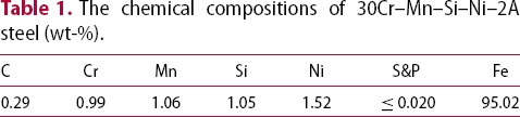
The chemical compositions of 30Cr–Mn–Si–Ni–2A steel (wt-%).

Phase diagram of 30Cr–Mn–Si–Ni–2A calculated by Thermo-Calc.
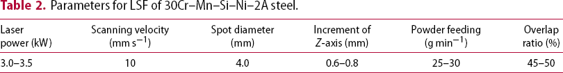
Parameters for LSF of 30Cr–Mn–Si–Ni–2A steel.
Metallographic samples were cut from the single-track multi-layer and multi-track multi-layer deposits, respectively. The samples were polished and etched by nitric acid alcohol solution. Optical microscope (OM) and scanning electron microscope (SEM) were used for characterising the microstructures. The microhardness of the deposits along the deposition direction was tested by a Duramin-A300 microhardness tester with the load of 500 g and load time of 15 s. The tensile properties were tested on an INSTRON 3382 electronic tensile machine with a loading rate of 1 mm min−1.
Thermodynamic simulation
Thermodynamic simulation was carried out using Thermo-Calc software developed by Royal Institute of Technology, Stockholm, Sweden. Figure 1 shows the calculated phase diagram of 30Cr–Mn–Si–Ni–2A under an equilibrium condition, critical temperatures for phase transformation were also attained from Thermo-Calc simulation results. Peritectic reaction between the liquid and δ-ferrite to produce austenite starts at 1484.8°C and stops at 1484.7°C, direct solidification from liquid to austenite phase stops at 1425°C, while α-ferrite begins to form from austenite at 758°C, precipitation of cementite starts at 714°C. The mole fraction of α-ferrite at 600°C is about 0.96 and the mole fraction of carbide precipitates is about 0.04 under equilibrium condition.
Results and discussion
Macro-morphology and dendrite structure of LSFed 30Cr–Mn–Si–Ni–2A steel
Macro-morphology and dendrite structure for the single-track multi-layer deposit of 30Cr–Mn–Si–Ni–2A steel are presented in Figure 2. It can be seen that the width of the deposit decreases with the deposition of the first three layers and then increases from layers 4 to 9, afterwards the width approaches to a stable value. A resemble change tendency in the layer thickness is also demonstrated with dark lines: the deposited layer thickness decreases for the first three layers and then increases from layers 4 to 7, and then approaches to a stable value. These can be partially attributed to the temperature increase caused by heat accumulation during the deposition process. For the first layer, the height of the deposited part is small, the molten pool tries to keep its contact angle with the substrate, gives a large pool width and captures more powders, so both the width and the height of the first layer are large. And for the subsequent layers when the deposition height increases, if the temperature is not high enough, some powders not melted by the molten pool falls down from the deposit, leads to the decrease in the layer width and the height. But if the temperature increases with heat accumulation, the dimensions of the molten pool increases and more powders are captured, then the layer width and the height increase till they approach to relatively stable values.
Macro-morphology images and dendrite structure of single-track multi-layer specimen of 30Cr–Mn–Si–Ni–2A steel by LSF. (a) Macro-morphology image, (b) directional dendritic structure, (c) CET, (d) dendrite structure in the cross-section.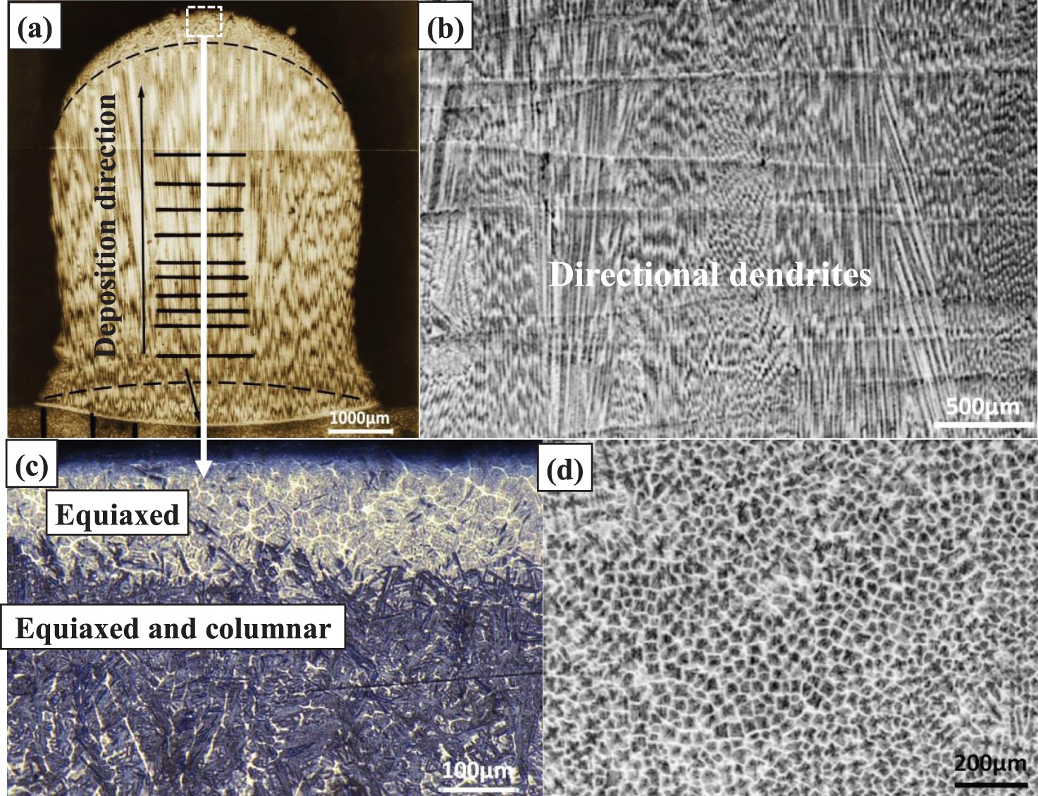
With the high-temperature gradient and growth rate in the molten pool, fine and uniform dendrite array were formed in the columnar grains observed, where the epitaxial columnar dendrites show the preferred growth orientation along the direction of highest temperature gradient, i.e. the deposition direction, as shown in Figure 2(a,b). An equiaxed crystal zone with thickness of about 300 µm was formed at the top of the deposit as a result of columnar to equiaxed transition (CET) in the solidification of the molten pool in the last layer, since temperature gradient decreased from the bottom to the surface of the molten pool (see Figure 2(c)). In fact the equiaxed crystal zone can be formed for each layer, but the subsequent laser deposition will re-melt the equiaxed zone of the former layer, only the equiaxed zone in the last layer can be preserved. This phenomenon has also been observed and explained in different alloy system and different AM process [16-18]. Cross-section of the epitaxial dendrites was given in Figure 2(d), from which the primary dendrite spacing can be measured in the range of 20–40 µm.
Typical structures of the multi-track multi-layer deposit are given in Figure 3, demonstrating the band structures and dendrite morphologies in this bulk deposit. Comparison between the dendrite morphology in the multi-track deposit with that of the single-track deposit shows that the uniformity of dendrite orientations in the multi-track deposit is decreased, as shown in Figure 3(b), the orientations of most of the dendrite array in the multi-track deposit are not in a strict up-right direction. Direction changed dendrites can also be observed in Figure 3(c). Complex temperature field with overlaps between the adjacent laser tracks may be a reason for the diversity of dendrite orientation in the multi-track deposit.
Columnar crystals and band structures in multi-track multi-layer specimen of 30Cr–Mn–Si–Ni–2A steel by LSF. (a) Band structures, (b) dendrites with different orientations, (c) direction changed dendrites.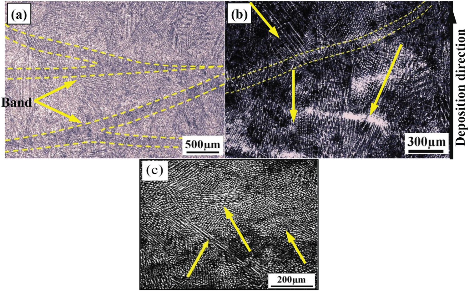
It has been shown that there exists an equiaxed dendrite zone with a thickness of about 300 µm in the single-track deposit. Since the equiaxed crystal zone are generally formed in the centre of the deposited track, it can be re-melted by the subsequent layer, thus not to be shown except in the top zone of the single-track deposit. But for the multi-track deposit, the situation is different: the deposited bulk provide a good thermal diffusion path leads to a partial re-melting of the equiaxed crystal zone, makes the survival equiaxed crystal or direction changed dendrites visible in the final structure. The band structures observed in the samples is an evidence for the re-melting process, and the bottom border of the molten pool formed by the scanning laser re-melting can be identified by these bands.
Microstructures and phase characterisation of LSFed 30Cr–Mn–Si–Ni–2A steel
Typical microstructures throughout the single-track multi-layer deposit of 30Cr–Mn–Si–Ni–2A steel are shown in Figure 4. Significant difference in the microstructures from the bottom to the top of the deposit can be observed. The bottom part of the deposit is mainly composed of super-saturated martensitic lath or plate, and lower bainite, which are denoted by M and BL in the pictures. During the deposition, the temperature of the deposited tracks can be maintained by the cycling heating from the deposition of the adjacent tracks and the subsequent layers, the repeated tempering effect transformed some of the martensite lath into tempered martensite (MT), as shown in the upright corner of Figure 4(e). Muhammad and Ameeq have shown that the temperature of 550–650°C is the most influential stage for the tempering of 30Cr–Mn–Si–Ni–2A steel [1]. The orientations of the acicular lower bainite structures were intersect with that of the martensite phase (see Figure 4(f)). With the increase of deposition height, martensite lath, lower bainite and tempered sorbate (ST) structures were observed in the middle part of the deposit. As the temperature of the deposited layers in the middle part of the deposit increased due to heat accumulation, the tempering effect in high-temperature zone turned the martensite lath into tempered sorbate structure, as shown in Figure 4(c,d). In the top part of the deposit, the microstructures were mainly composed of the martensite clusters and bainite, as shown in Figure 4(a,b).
The microstructures of single-track multi-layer specimen by LSF. (a) OM image and (b) SEM image for the top zone. (c) OM image and (d) SEM image for the middle zone. (e) OM image and (f) SEM image for the bottom zone.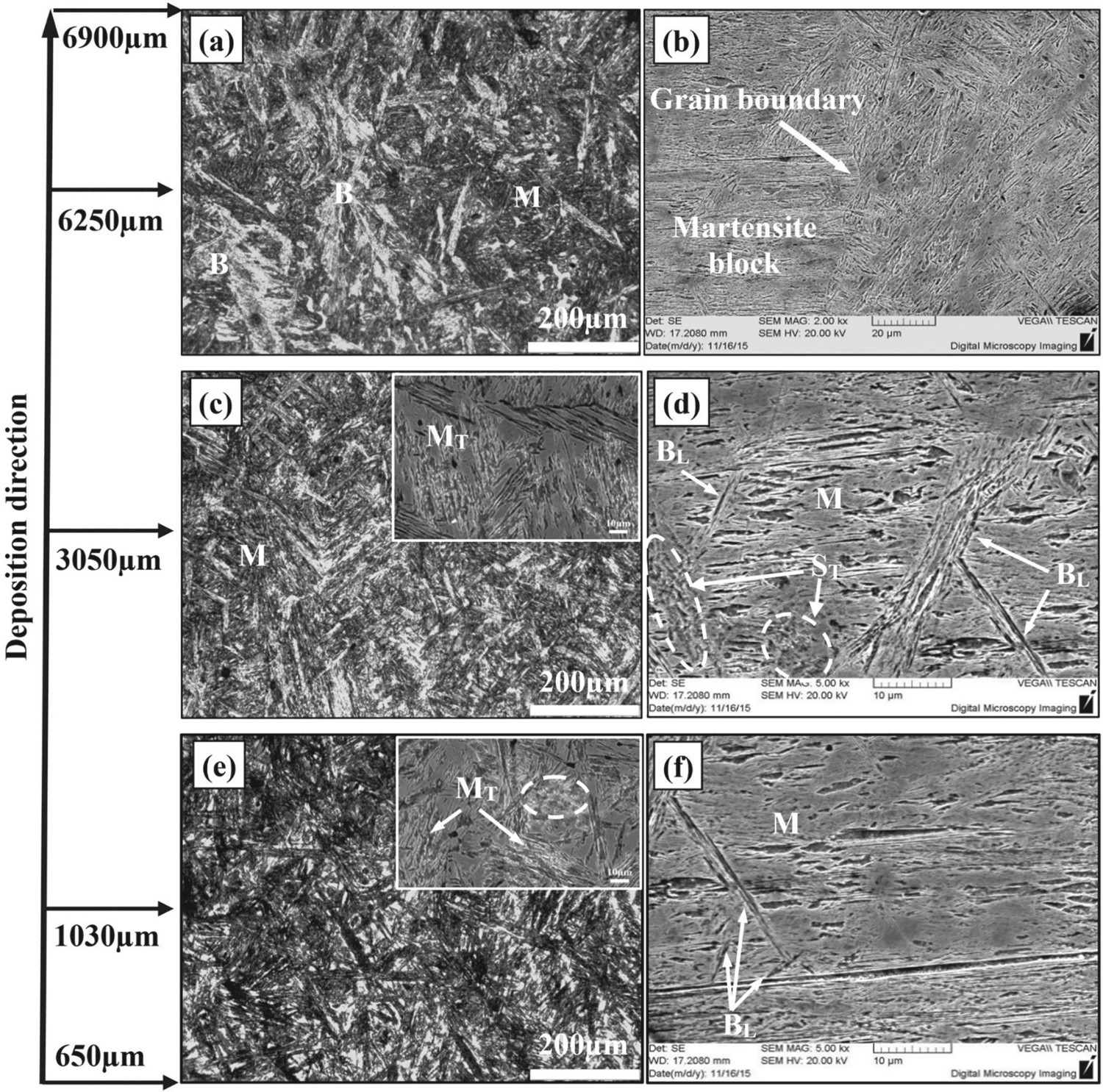
Microstructures along the deposition direction throughout the multi-track multi-layer deposit of 30Cr–Mn–Si–Ni–2A steel produced by LSF process are shown in Figure 5. The bottom zone of the deposit was mainly composed of the tempered martensite, as shown in Figure 5(i,j). Acicular lower bainite structures began to appear in the lower middle zone of the deposit, and the volume fraction of lower bainite increased with the increase of deposition height from the lower middle zone through the middle zone and then to the upper middle zone (Figure 5(g–h), (e–f), (c–d)). Mixed structures of martensite and bainite were observed in the top zone, where martensite, lower bainite, and upper bainite were observed, and the volume fraction of bainite was higher than that in other parts of the deposit. These differences among the microstructures along the deposition direction can be explained by the temperature increasing with the heat accumulation and cycling heating effect from the subsequent laser scanning.
The microstructures of multi-track multi-layer specimen by LSF. (a) OM image and (b) SEM image for the top zone. (c) OM image and (d) SEM image for the upper middle zone. (e) OM image and (f) SEM image for the middle zone. (g) OM image and (h) SEM image for the lower middle zone. (i) OM image and (j) SEM image for the bottom zone.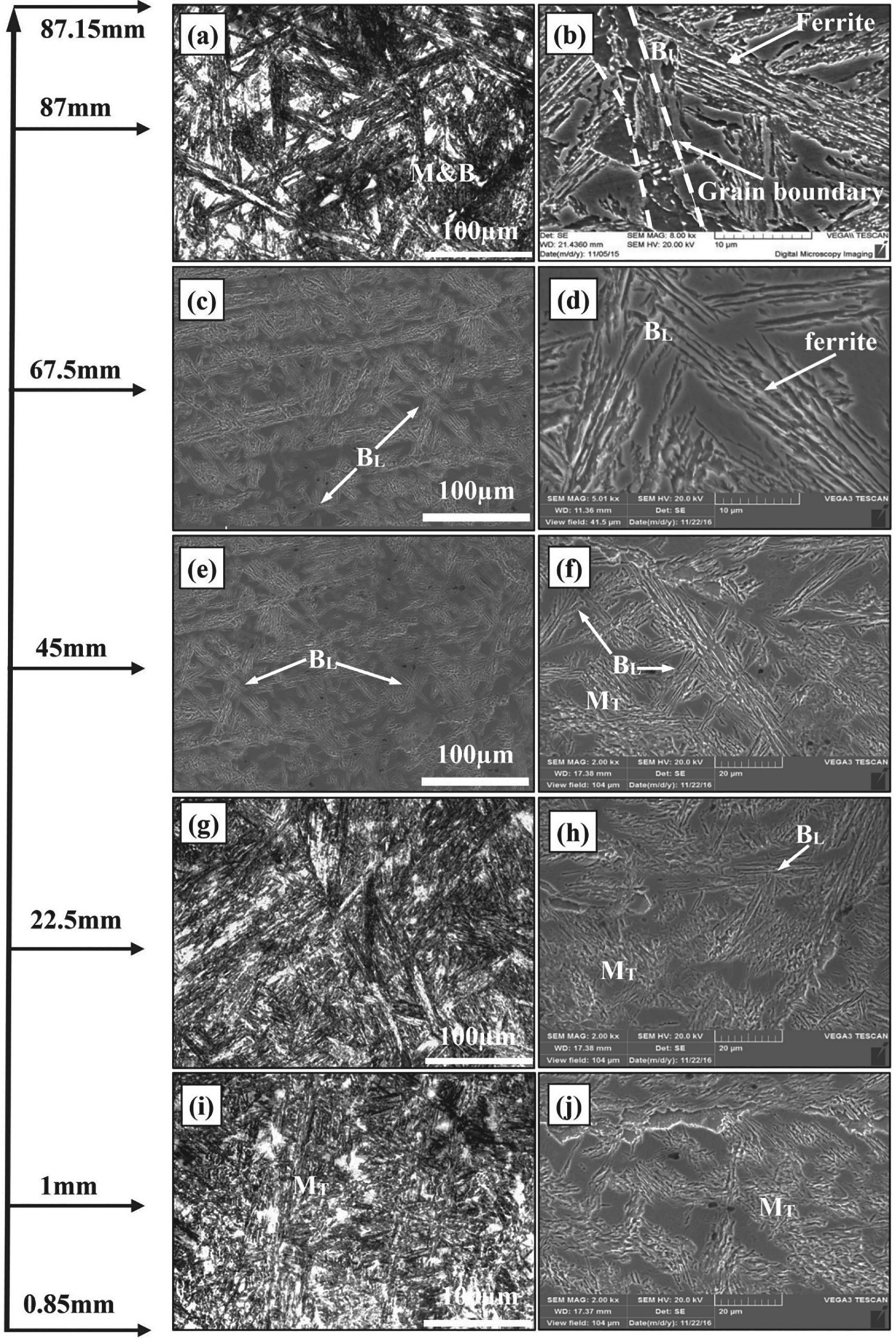
For the first few layers, as the dimension of the molten pool is much small when compared with the large substrate, the temperature gradient and cooling rate in the molten pool is high, fine martensite was formed from the pre-solidified austenite phase. During the forming process, cycling heating induced by subsequent laser deposition provides a repeated tempering condition for the martensite phase. Because the martensite phase in the lower part of the specimen endured more tempering cycles, typical martensite morphology with soft interface was shown in the bottom zone (see Figure 5(j)), demonstrating a higher tempering degree.
In the forming process, temperature gradient and cooling rate of the molten pool and the deposited layer decreased because of heat accumulation with the increasing of deposition height, the pre-solidified austenite phase partially transformed to bainite structures, lead to a mix structure of martensite, bainite, and residual austenite. Previous researchers have investigated the temperature field for laser deposition in different alloy systems [19, 20], which showed that the temperature of the molten pool can be above 1300°C, and the cycling temperature of heat affect zone (HAZ) covered the lower bainite starting transition temperature for 30Cr–Mn–Si–Ni–2A steel. According to the metallurgical observation result, the tempering under higher cycling temperature range transformed the solidified martensite into tempering martensite, and the residual austenite transformed to lower bainite structure in the cycling temperature range.
With further increasing of the deposition height, both the temperature of the molten pool and cycling heating are relatively stable, the upper middle zone of the deposit was characterised by martensite and lower bainite structures, and the volume fraction of lower bainite increased with the increase of deposition height. At the top zone of the deposit, the transformation temperature of upper bainite may be reached by the cycling heating, and the feathered upper bainite began to appear in this part of the deposit. Usually, the upper bainite structures are composed of the flake ferrite and cementite particles, but as there is silicon element with a content of 0.90–1.20% in 30Cr–Mn–Si–Ni–2A steel which can stabilise the austenite but hinder the precipitation of cementite. It can be observed that the upper bainite structures of the deposit were composed of the flake ferrite and residual austenite. This phenomenon can also be observed in other silicon-containing steels.
With the diversity of the microstructures for single-track or multi-track deposits along the depositing direction, the most important characteristic in LSFed 30Cr–Mn–Si–Ni–2A steel is the existence of martensite phase. It can be observed that the scales of the martensite laths increased with the deposition height, even martensite block can be observed in the top zone of the deposit, this is relevant to the heat history of the deposits. With respect to the solidification of 30Cr–Mn–Si–Ni–2A steel, normally high-temperature ferrite phase was solidified from the melt first, austenite phase was formed by the peritectic reaction, and then by direct transformation from the survival melt. In the solid-state transformation process, ferrite was transformed to austenite, if the cooling rate exceeded a critical value, martensite was formed from austenite phase. In this sense, the primary formed ferrite phases and the dendrite arm spacing will affect the scales and volume fraction of the formed martensite, and then lead to the different mechanical properties in a different zone of the deposit.
Microhardness of LSFed 30Cr–Mn–Si–Ni–2A steel
Block deposit of 30Cr–Mn–Si–Ni–2A steel was prepared by multi-track multi-layer deposition, the microhardness on the deposit section along the building direction were measured and presented in Figure 6, showing the variation of microhardness on the deposit with the distance from the substrate. From Figure 6 we can see that the microhardness in the bottom zone of the deposit shows hardness of about 495 HV, in the lower to middle zone of the specimen the hardness values are ranged as 410–440 HV, in the upper middle zone a minimum hardness value of about 390 HV was reached, and then the hardness value increases to the top of the deposit with a final value of 485 HV.
The microhardness of multi-track multi-layer specimen by LSF.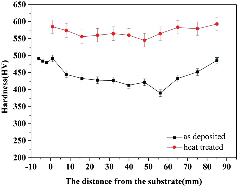
This V-type curve distribution of microhardness can also be explained by the inhomogeneous microstructures formed during the deposition process. Both the solidification and solid-state transformation contributed to the final structures, and heat accumulation and cycling heating effect provided different phase transformation condition throughout the whole deposit. As a result, the bottom zone of the deposit was characterised by the tempering martensite that possesses the highest hardness; with the increase of the deposition height, the volume ratio of bainite structures increases, in the same time the residual stress in the martensite phase was released, lead to the decrease of the hardness. At the top zone of the deposit, with the higher temperature reached by heat accumulation, the sizes of the formed martensite lath increased and even martensite block can be observed, as tempering effect with cycle heating of subsequent layers was not presented at this zone, leading to an increase in the hardness in the top zone of the deposit.
Microhardness at different point of the heat treated specimen were also given in Figure 6. It is shown that the microhardness were increased and more uniformly distributed, with values ranged between 540 and 590 HV.
Tensile properties of LFRed 30Cr–Mn–Si–Ni–2A steel
Tensile samples were prepared for the transverse sections from the bottom zone, middle zone and top zone of the deposits, samples from longitudinal section were also prepared. The room temperature tensile properties of the samples were presented in Figure 7. The tensile properties of a wrought 30Cr–Mn–Si–Ni–2A steel sample was also included for comparison.
The tensile test results of the laser solid formed 30Cr–Mn–Si–Ni–2A steel.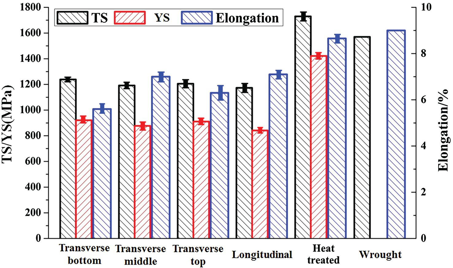
Overall, the as-deposited tensile properties are lower than that of the standard wrought part, and there exist distinct anisotropy on the as-deposited tensile properties of the deposits. The samples from the longitudinal section show a tensile strength of 1173 MPa, a yield strength of 841 MPa and an elongation of 7.1%. The samples from different transverse sections present different tensile properties, the sample from the bottom zone has the highest tensile strength of 1238 MPa, yield strength of 921 MPa but the lowest elongation of 5.6%, the sample from the middle zone has the lowest tensile strength of 1191 MPa, yield strength of 877 MPa but the highest elongation of 7.0%, the tensile properties of sample from the top zone lies in between, with tensile strength of 1205 MPa and an elongation of 6.3%. After heat treatment, the tensile properties of the sample are stronger than the standard wrought part, with tensile strength of 1720 MPa, yield strength of 1430 MPa, but a lower elongation rate of 8.7%.
It can be deduced from the metallurgical observation and the mechanical properties analysis that, due to the different heat history for different part of the deposit, the LSFed 30Cr–Mn–Si–Ni–2A steel shows the inhomogeneous microstructure and possesses un-evenly distributed mechanical properties. Heat treatment can be applied to enhance the mechanical properties of LSFed 30Cr–Mn–Si–Ni–2A.
Conclusions
The microstructure of LSFed 30Cr–Mn–Si–Ni–2A steel is mainly composed of the epitaxial columnar grains, and CET occurs at the top of the deposit; some equiaxed grains or direction changed dendrites can be observed in the multi-track multi-layer deposit. Along the deposition direction, the microstructure at the bottom of the deposit is mainly composed of the tempered martensite; the middle to top zone of the deposit is characterised by a mixture of tempered martensite and bainite, with the further increase of deposition height, the fraction of bainite gradually increases, the size of martensite lath increases but its volume fraction decreases. The microhardness of the deposit shows a V-type curve along the deposition direction, showing a decrease from the bottom zone to the middle–upper zone, and then a significant increase at the top of as-deposited 30Cr–Mn–Si–Ni–2A steel. The deposits demonstrate anisotropic and unevenly distributed tensile properties, heat treatment is applied to optimise the mechanical properties of LSFed 30Cr–Mn–Si–Ni–2A, provides tensile strength of 1720 MPa and elongation rate of 8.7%.
Footnotes
Disclosure statement
No potential conflict of interest was reported by the authors.