
Abstract
The current demand for vehicles with high fuel efficiency, improved safety and enhanced crashworthiness qualities is being met by making use of high strength components with tailored mechanical properties which are made using tailor-welded blanks. During their production, the surface of the blank needs to be protected against oxidation and decarburisation. Protective coatings are used to protect the steel surface, with Aluminium-Silicon or Zinc-based coatings being the most popular. This work provides a review on the state-of-the-art as well as the issues associated with the laser welding of coated 22MnB5 grade steel to be used in the production of tailor-welded blanks. The paper provides a summary of existing solutions available to overcome these issues while discussing their limitations and the potential for future work.
Keywords
Motivation
Ultra-high strength steels (UHSSs) are a family of advanced high strength steels (AHSSs) with an ultimate tensile strength (UTS) that is higher than 780 MPa as shown in Figure 1. UHSSs, specifically, press-hardened (or hot-stamped) steel (PHS) allows the manufacturing of extremely high strength automotive structural components that help to reduce vehicle weight, improve safety and the overall structural integrity of the vehicle, and drastically advances the crashworthiness qualities of future cars [1].
Schematic showing various grades of steel ranging from low to mild strength conventional steels to UHSSs that include 3rd generation AHSSs as well as twinning-induced plasticity steels, martensitic steels, dual-phase and MnB-alloyed press-hardened steels..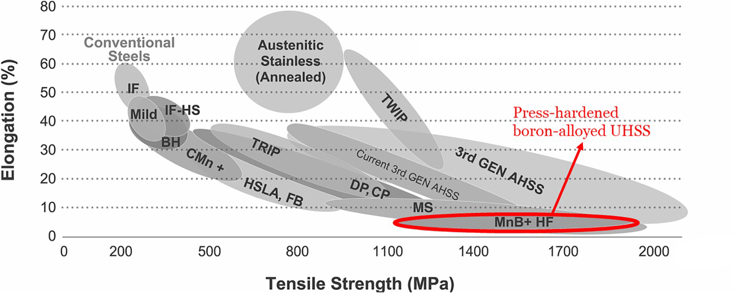
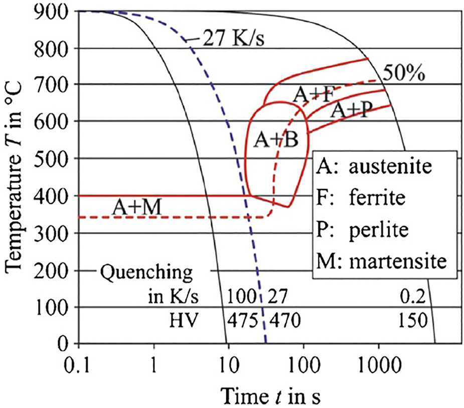
PHSs are manganese-boron-alloyed steels that have a UTS of about 600 MPa in the as-received (AR) condition. The most commonly used grade of PHS is 22MnB5 and it has been shown by Naderi that this grade of steel produces a fully martensitic microstructure after the austenitisation and quenching process with a cooling rate of at least 27 K/s, resulting in a UTS of up to 1500 MPa [3].
In recent years, the development of anti-intrusion automotive components made from UHSSs have been given a further boost in terms of crashworthiness qualities, part consolidation, and overall weight reduction by joining them with PHSs to make blanks with tailored properties [4]. A variety of automotive chassis components are made from PHSs that include the A-pillar, B-pillar, bumper, rocker and roof rail, and the tunnel as shown in Figure 2 [5]. In order to produce components with the desired tailored properties and make the best use of PHSs, they must either have their mechanical properties locally adjusted, for instance through local tempering processes, or they must be joined with other grades of PHSs with varying thicknesses and properties [6]. The most common way to join different types of PHSs is by using laser welding such that two or more types of PHSs are laser welded together to form a laser-welded blank (LWB), also referred to as a tailor-welded blank (TWB), which is then hot-stamped to make the component with the desired geometry, shape and mechanical properties.
Usage of hot-stamped components in a middle-class sedan showing that the key difference between Gen I vehicles compared to Gen II vehicles is the usage of UHSSs which has increased from about 7% to about 33%, respectively.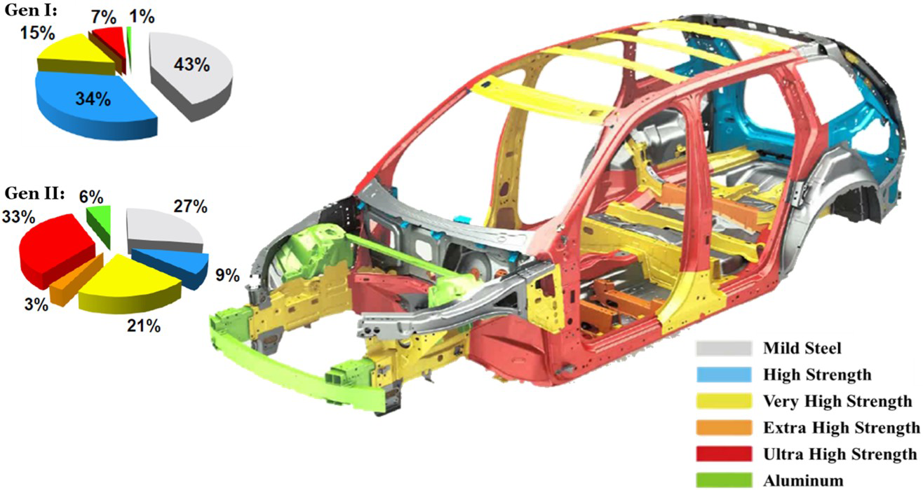
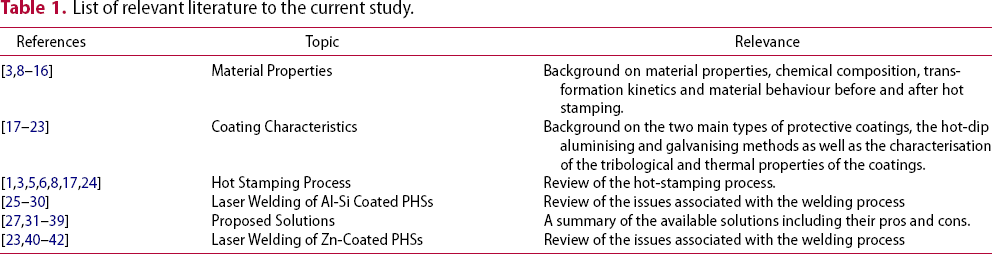
List of relevant literature to the current study.
22MnB5 grade press-hardened steel
Material properties
As the need for parts with complex shapes, good formability, toughness, and impact resistance increases, the traditional high strength low alloy steels do not meet the present day requirements of the automotive industry as their strength is limited and they are relatively expensive [9]. The usage of boron steel sheets has been recognised as an excellent alternative to more traditional grades of UHSSs due to the ability of boron to act as a strong hardening agent with excellent hardenability while still allowing for the steel to have good formability. A boron addition of 30 ppm gives a hardenability increase equivalent to 0.6 wt-% Mn or 0.7 wt-% of Cr or 0.5 wt-% of Mo or 1.5 wt-% of Ni [10]. Boron-alloyed steels such as 22MnB5, 27MnCrB5, and 37MnB4 grades are the only types of PHS that produce a fully martensitic structure when utilising a water-cooled die [3]. Amongst these, 22MnB5 is the most commonly used grade for automotive hot stamping (HS) applications due to the fact that after HS, it exhibits a UTS of about 1500 MPa and a yield strength of 1100 MPa as shown in Figure 3 [5].
Mechanical properties of 22MnB5 in the AR condition and in the PHS condition relative to other grades of steel. From and Tekkaya [43]. Reprinted with permission from Elsevier.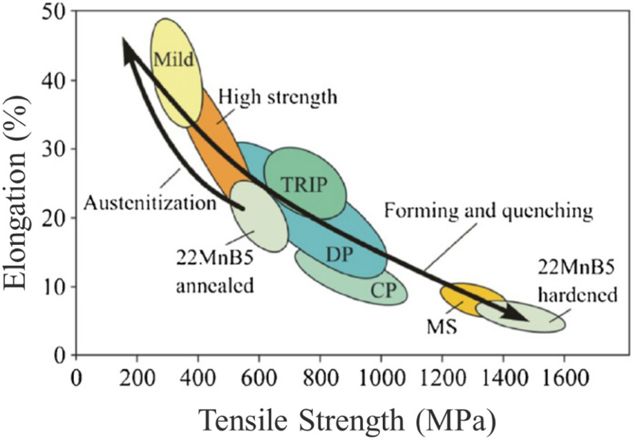
The typical microstructure of boron-alloyed steel in the as-received condition predominantly comprises of ferrite, pearlite, and a small amount of martensite located at the ferrite grain boundaries as shown in Figure 4 (a). The typical morphology of the material in the hot-stamped condition is that of lath martensite as shown in Figure 4 (b). In general, it is observed that the laths are parallel to each other with some of the laths containing distributed carbides which is thought to be a consequence of auto-tempering [26].
Base metal microstructure of 22MnB5 press-hardened steel (a) As-received condition; (b) Hot-stamped condition. From Saha et al. [44].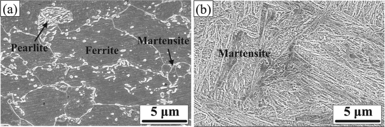
The addition of very small quantities of boron, typically ranging from around 10–30 ppm, to low alloy steels boosts the hardenability of the steel [12]. The reason for this increase in hardenability is attributed to the segregation of boron to the austenite grain boundaries. The boron segregation changes the austenite grain boundary characteristics (grain boundary surface energy modification [11, 13] causes the formation of
Flow curves and microstructure evolution of 22MnB5 during HS as it goes from a BCC crystal structure in the as-received state to an FCC crystal structure when fully austenitised and finally achieving a BCT crystal structure following the quenching and forming stage. From Karbasian and Tekkaya [43]. Reprinted with permission from Elsevier. intermetallic particles [14, 15]) which delay the heterogeneous nucleation of ferrite at the austenite grain boundaries [12, 16, 45]. The effect of manganese is also important as it is an effective hardening agent that helps retard most austenite decomposition reactions [8]. The two alloying elements together help to push the CCT diagram shown in Figure 7 to the right by decreasing the cooling rate necessary to avoid ferrite formation during cooling whereby increasing the possibility of attaining a fully martensitic microstructure at the end of the HS process. The transformation of 22MnB5 from a primarily ferritic (bcc) structure to austenite (fcc) during the heating stage and then to martensite (bct) during the rapid quenching stage can be seen in Figure 5.

Coating properties
Surface oxidation and corrosion is an issue for all components made of steel. PHSs are no exception to that rule with the oxidation of the steel surface becoming more rapid and aggressive at the elevated forming temperatures during the HS process. Uncoated 22MnB5 is plagued with the formation of oxide scale on the surface due to thermal oxidation at elevated austenitisation temperatures. Previously, chromium shot blasting was used to blast away the oxide scale which consequently left behind a thin Fe–Cr layer that helped prevent further oxidation and corrosion, and eliminated the need to reapply an oil coating [8]. Following from the same line of reasoning, 22MnB5 steel was made available with surface coatings that provided some type of barrier or sacrificial protection as well as protection against decarburisation during the heating stage. The most common and widely used coating is the
 –
–
 coating that has been developed by ArcelorMittal under the trade name of UsiborⓇ 1500P (aka UsiborⓇ AluSi). The coating is applied through a process known as hot-dip-aluminising [17]. Due to the fact that the electrochemical potential of this Al–Si-Fe coating is so close to that of the base material there is not enough of a chemical potential difference required to provide adequate sacrificial protection and therefore, it is primarily used as a barrier protection that provides protection against oxidation as well as decarburisation.
As an alternative to the Al-Si coating, zinc-coated steels in the form of galvanised (GI)
 –
–
 and galvannealed (GA)
 –
–
 steels are also quite popular [18]. The zinc-based coatings come with their own set of problems with the most relevant being liquid metal embrittlement (LME). LME is a phenomenon that is generally observed between two metals with low mutual solubility. During the HS process liquid zinc from the coating seeps into the austenite grain boundaries due to the low solubility of zinc in the austenite phase and as the liquid metal propagates through the grain boundaries by way of diffusion, the material undergoes decohesion and LME-cracks are formed.
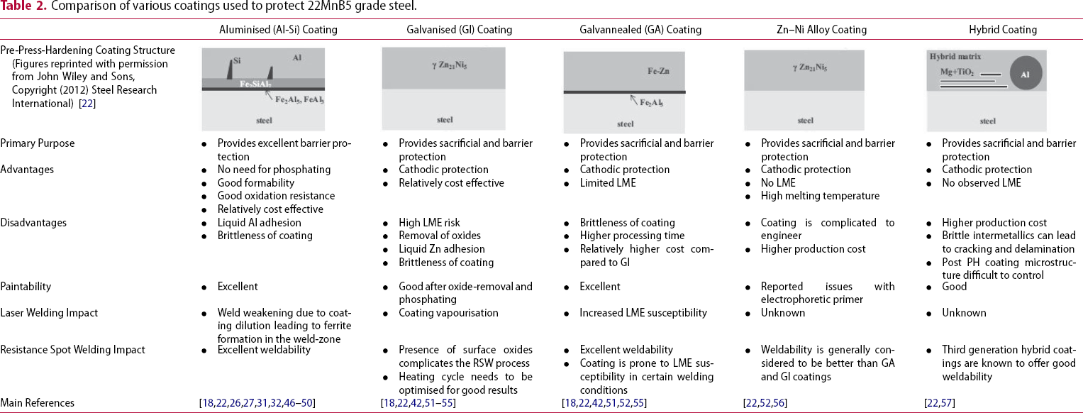
Comparison of various coatings used to protect 22MnB5 grade steel.
The hot stamping process
Developed in Sweden in 1977 by a company called Plannja, HS was first used as a process to manufacture sawblades and lawn mower blades [58]. The first known use of the HS technology in the automotive industry was by Saab Automobile AB in 1984 [58]. The technology was slow to catch on with only 3 million parts produced in 1987; however, in a span of 20 years production of hot-stamped parts had increased to 107 million parts/year in 2007 [58].
There are two main methods of HS as shown in Figure 6. The most commonly used method for HS is known as the direct HS method as shown in Figure 6(a). This method requires that the blank should be heated up to an austenitisation temperature (T >
 or 850–950°C) and held for about 4–10 min, after which the blank is rapidly transferred to the HS press where it is simultaneously quenched and formed using a water-cooled die for about 6–10 s [5]. If the cooling rate exceeds the critical cooling rate required for a complete diffusion-less transformation of austenite to martensite, an ultra-high strength (UTS ∼ 1500–2000 MPa) will be achieved as shown in the continuous cooling transformation (CCT) curve in Figure 7 [59]. In order to ensure no bainite or ferrite forms in the microstructure, the blank must be rapidly transferred from the furnace to the press [3].
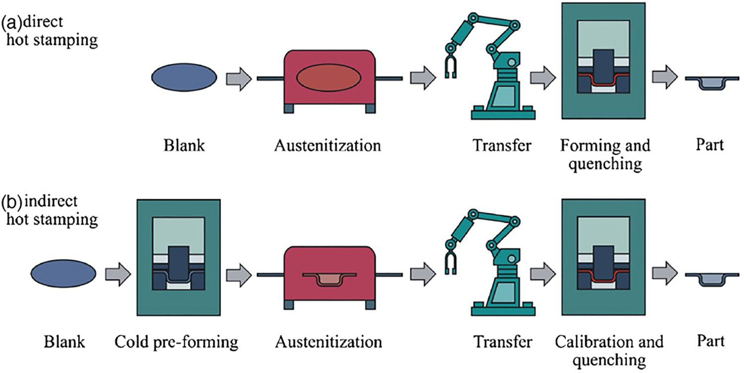
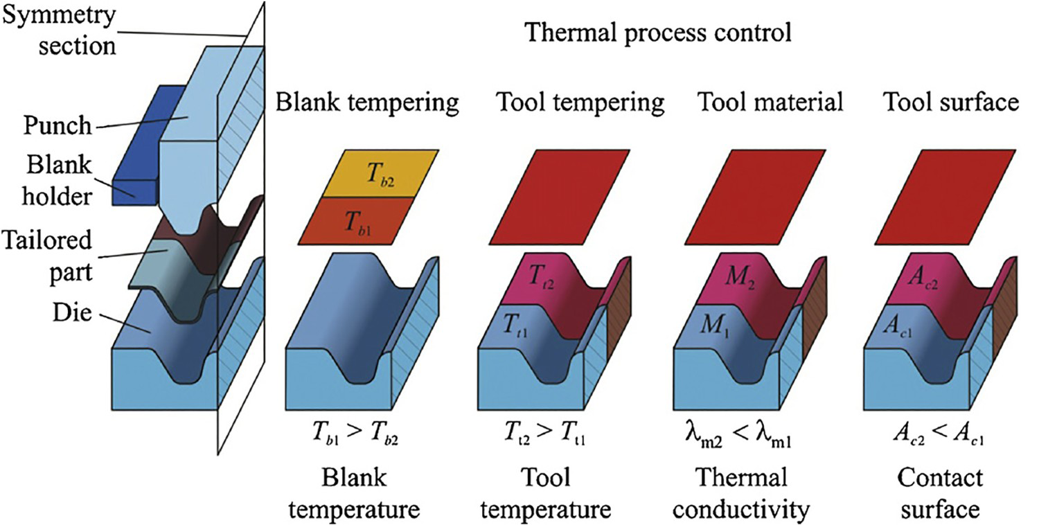
The indirect HS method shown in Figure 6(b) starts with a cold-formed part that is subsequently austenitised in a furnace, followed by various thermal process control strategies that include quenching and calibration techniques that produces the final part with tailored properties as shown in Figure 8. A detailed review has been provided on the various types of indirect HS techniques elsewhere [5, 6].
Production of TWBs
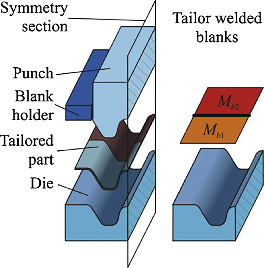
The most common method used to produce vehicle components with tailored properties is known as TWBs, sometimes referred to as LWBs. In this method, two or more types of steel with varying thicknesses are joined together using laser welding and then the blank is hot-formed into the required part using the direct HS approach as shown in Figure 9. The benefits of using this technology are listed as follows:
The technology significantly simplifies the manufacturing process which saves time and money. By joining different types of steels together with varying thicknesses the part can be optimised by reducing its weight and improving its performance. Two or three separate parts can potentially be consolidated into one single component. In general, using TWBs leads to a material cost reduction.
CO2 and fibre lasers are most commonly used to produce TWBs by joining Al–Si coated 22MnB5 steel to various other grades of steel. The Zn-coated GI and GA grades of steel are difficult to use for this application due to the vapourisation of the GI coating during fibre laser welding (FLW) and the potential of LME cracking when using the GA coating [42]. The issues associated with the laser welding of Zn-coated 22MnB5 are discussed in a later section. As far as the alternative coatings discussed in Table 2 are concerned, none of them have gained enough traction or popularity to be used in abundance when manufacturing TWBs.
Al–Si10% coated 22MnB5 PHS
Protecting 22MnB5 grade steel against heat and oxidation is very important to assure the manufacturing of quality parts with good surface finish that can be used directly in car body-in-white (BIW) applications. Hot-dip-aluminising is an effective and affordable way to provide the required protection for PHSs against scaling and decarburisation [18]. As shown in Figure 10, the aluminising is carried out in the form of a continuous process where the base metal steel sheet Method for manufacturing hot-dip aluminised steel sheets showing that the steel sheet is continuously dipped in a molten bath of Al-Si and the coating solidifies as the steel leaves the bath. From Kobayashi et al. [19].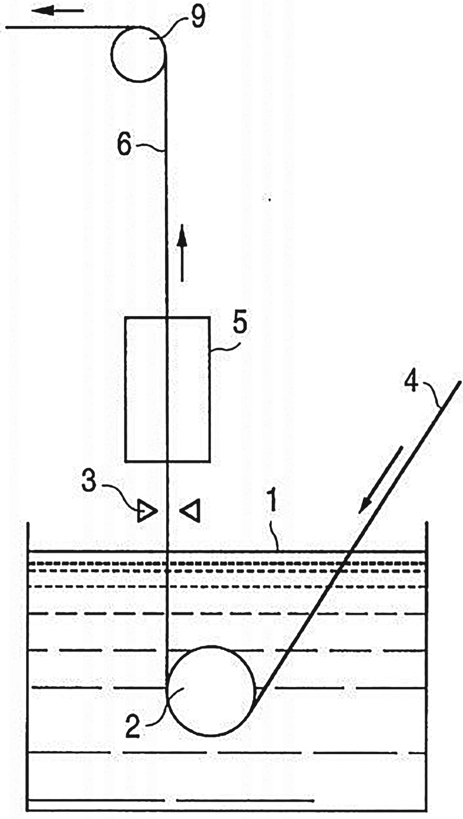
The addition of Si to the aluminised coating is to form an intermetallic inhibition layer of
 between the coating and the steel substrate. The
 layer prevents the formation of brittle intermetallics at temperatures below 550°C [21]. During the HS process, the service temperature is much higher than 550°C so the Fe–Al intermetallic phase formation reaction is much faster. However, in the absence of Si it was observed that there is rapid growth of the brittle
 intermetallic phase into the steel substrate forming a wavy coating-steel interface at elevated temperatures [20]. The
 phase is extremely detrimental to coating adhesion and material formability due to the phase being very hard and brittle. Si is very effective at controlling the inward protrusions of the intermetallic phase into the steel substrate leading to a flat coating-substrate interface and much improved coating properties [22].
Fibre laser welding of Al–Si coated 22MnB5 PHS
When 22MnB5 steel is welded in the absence of a surface coating, the fusion zone (FZ) is shown to have a purely martensitic microstructure as shown in Figure 11. This means that the weldment has the same microstructure as well as the same physical properties as the base metal in the hot stamped condition. However, due to the corrosion and oxidation susceptibility of the 22MnB5 steel grade, it usually comes with a protective Al–Si coating. During FLW of Al–Si coated 22MnB5, the coating melts and mixes into the molten weld pool as shown in Figure 12 (a) and (b) [25]. This leads to the formation of a dual-phase region in the FZ comprising of ferrite and martensite in both the as-received welded (ARW) and the as-received welded then hot-stamped (ARWHS) condition as shown in Figure 12 (c).
Schematic showing (a) the laser welding of Al-Si coated 22MnB5 steel with a cross-section of (b) the molten weld pool showing the mixing pattern of the Al-Si coating and (c) the solidified FZ showing the dual-phase microstructure with ferrite dispersed in a martensitic matrix.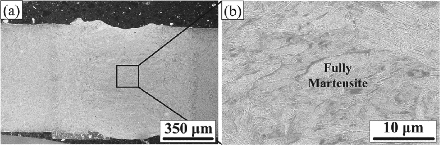
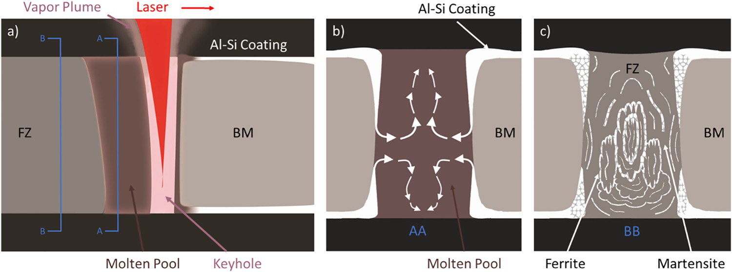
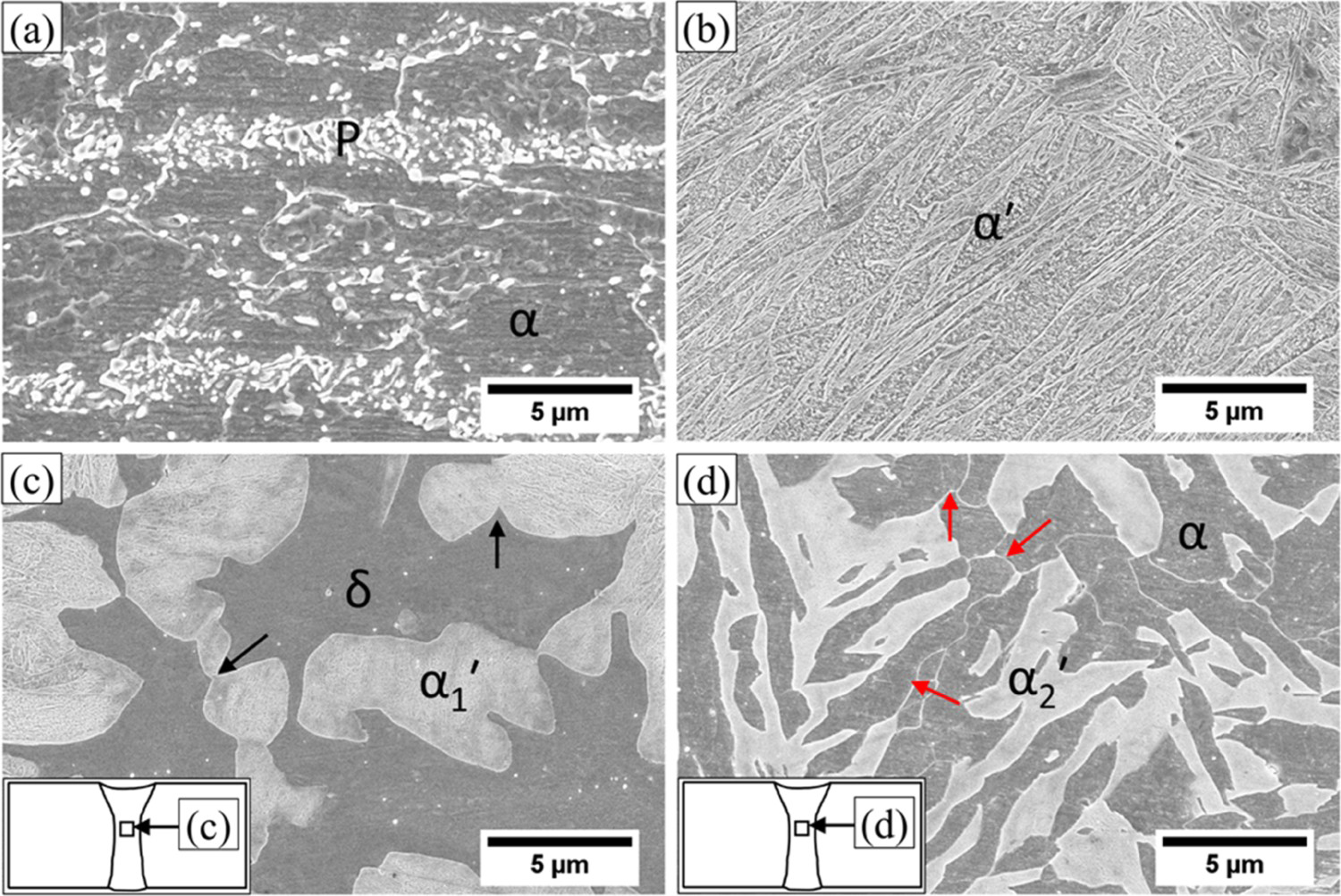
Figure 13 shows the representative SEM micrographs illustrating the (a) ferritic-pearlitic dual-phase region in the as-received BM, (b) fully martensitic microstructure in the press-hardened BM, (c) a combination of high-temperature δ-ferrite and
 ′ martensite phase in the FZ of the ARW material, and (d) a combination of low-temperature α-ferrite and
 ′ martensite phase in the FZ of the ARWHS material.
Bright-field Transmission Electron Microscopy (TEM) was used to show that the dual-phase region seen in the weldment is a combination of high-temperature δ-ferrite and martensite in the ARW condition, and it is a combination of the low-temperature α-ferrite and martensite phase in the ARWHS condition [30]. Figure 14 shows the bright-field TEM images of the FZ in the ARW sample showing: (a) a mixture of δ-ferrite and martensite (
 ′) phase, (b) lower bainite microconstituents, and diffraction patterns of (c) δ-ferrite in [
 ] projection, (d)
 ′ in [
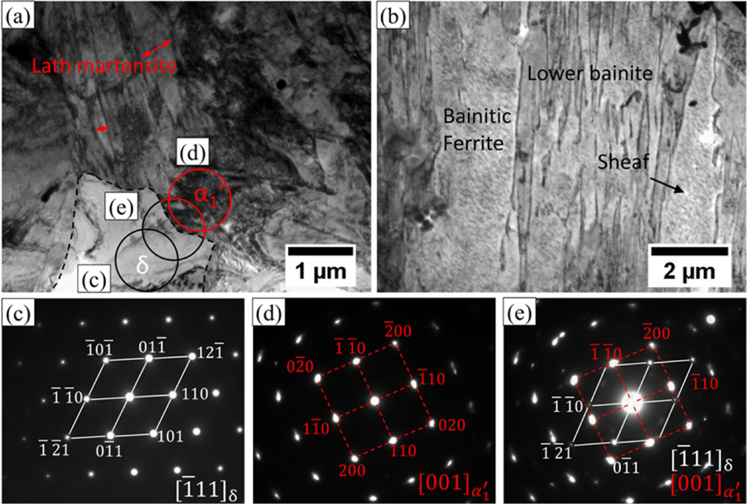
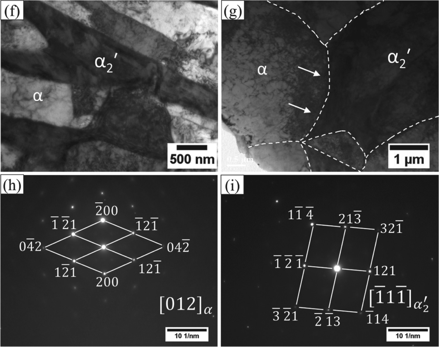
Figure 15 shows the bright-field TEM images of the FZ of the ARWHS sample showing: (f) a mixture of α-ferrite and martensite (
 ′) phase, (g) magnified view of α-
 ′ interface, and the diffraction patterns of (h) α-ferrite in projection, and (i)
 ′ in [
 ] projection.
Effect of FZ ferrite on the mechanical properties of the weld
The ferrite phase in steels is softer and more ductile than the martensite phase found in PHS. Figure 16 shows the nano-indentation study of the different phases present in the FZ of the (a) ARW, (b) ARWHS, and (c) Hot-Stamped then Welded (HSW) condition. It was observed that the nanohardness of the martensite phase ranged from 7.1 to 7.9 GPa and that of the ferrite phase ranged from 4.5 to 4.9 GPa, for all three sample conditions. Interestingly, it was noted that the lowest nanohardness for the martensite phase was observed in the ARWHS sample (7.1 ± 0.6 GPa) which was attributed to the lower quenching rate in the HS condition and the presence of the smaller stress-free martensite grains [26].
Nanoindentation study of the different phases present in the weldment for the (a) ARW, (b) ARWHS, and (c) HSW condition. (d) is the bar graph showing the relative difference in nanohardness between the martensite and the ferrite phases present in the different conditions. From Saha et al. [2016]. Reprinted with permission from the Welding Journal [44].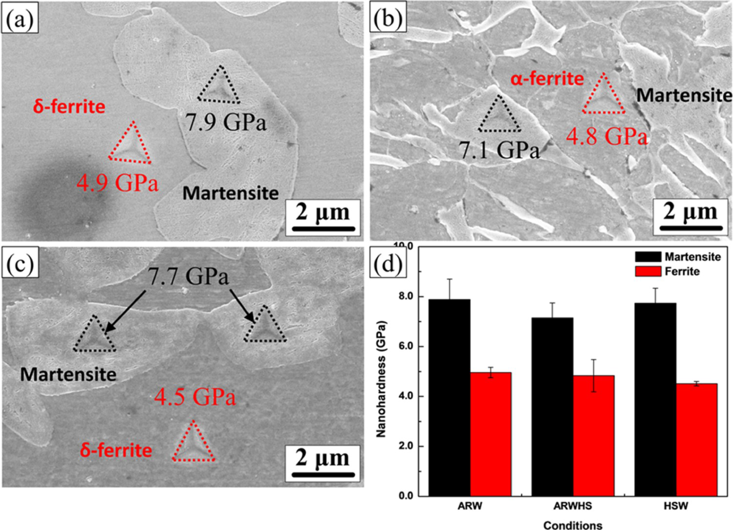
Figure 17 shows the characteristic microhardness profile across the FZ in the (a) ARW and (b) ARWHS condition with and without the presence of the Al–Si coating. It has been reported that the as-received BM (ARBM) hardness for 22MnB5 steel is about 250 HV and the hot stamped BM (HSBM) hardness ranges from about 500–550 HV [25, 27, 28, 30]. The FZ hardness is observed to be lower in both the ARW and ARWHS conditions when the welds are made through the Al–Si coating compared to when the Al–Si coating is removed before welding [27, 31].
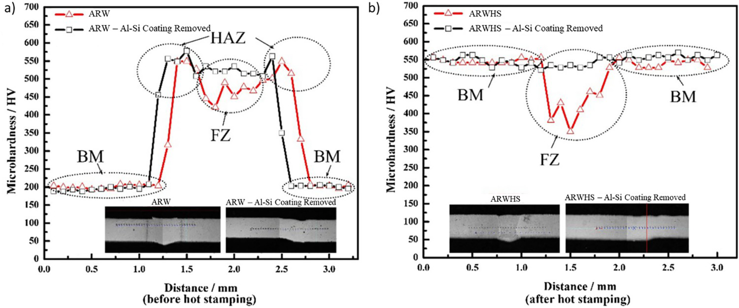
Figure 18 shows the characteristic engineering stress vs. strain curves of the BM. For the as-received samples, the yield strength and the UTS of the ARW sample showed a negligible difference when compared to the ARBM. In the case of the hot stamped samples, the non-welded sample (i.e. HSBM) was seen to have the highest UTS and engineering strain, whereas, both the welded samples (i.e. HSW and ARWHS) exhibited a much lower UTS while also showing a significant loss in elongation. The lower hardness observed in the FZ of these samples indicates that the load carrying capacity of the FZ is compromised whereby leading to catastrophic failure in the weldment.
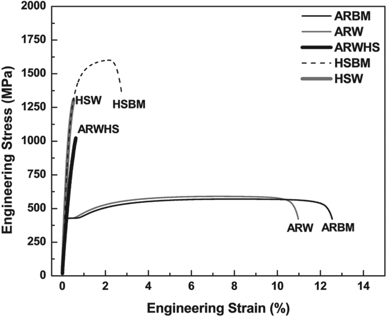
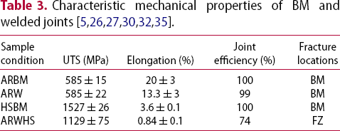
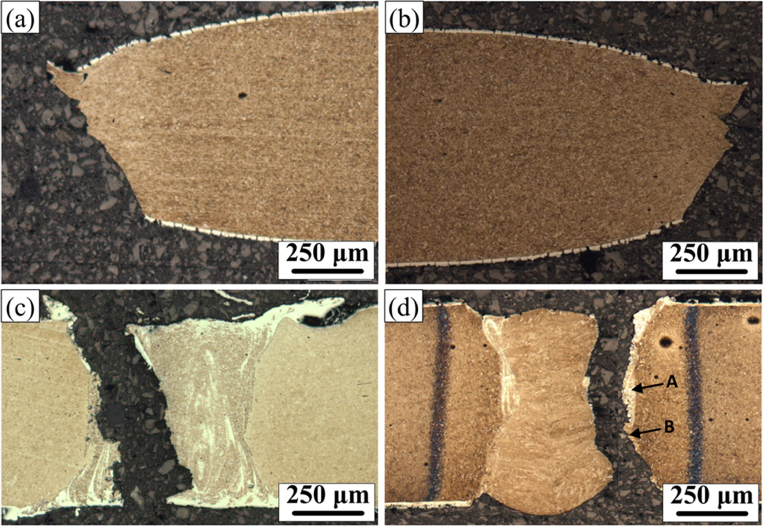
Figure 19 shows the failure conditions in the (a) ARBM and ARW condition, (b) HSBM condition, (c) ARWHS condition, and (d) HSW condition. It can be seen that welding in the as-received condition has no significant impact on the mechanical properties of the joint as failure occurs in the BM in both the ARW and ARBM conditions. However, in the ARWHS condition, failure is seen to initiate at the fusion boundary and then propagates through the FZ following the network of low-strength α-ferrite dispersed through the weldment. The joint efficiency in the ARWHS condition is about 74% which is extremely poor when compared to the HSBM. Similarly, the joint is seen to fail in the fusion boundary in the HSW condition which can be explained by the presence of the heat affected zone (HAZ) surrounding the FZ and the presence of the δ-ferrite phase along the boundary of the weld.
Ferrite Evolution in the weld zone
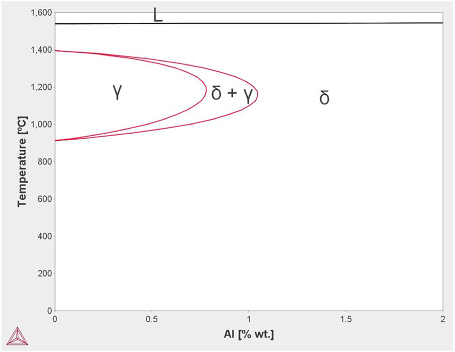
According to Martin et al. [62] aluminium is a strong ferrite stabiliser that shrinks the single-phase austenite region while promoting ferrite formation that consequently leads to the growth of the two-phase ferrite-austenite region on the Fe-Al phase diagram. In fact, it has been reported that an Al-content of greater than 1.2 wt-% completely inhibits the formation of the austenite phase [34]. Figure 20 shows the Fe–Al phase diagram that confirms that during cooling, the δ-ferrite phase forms first from the liquid phase (L), after which a peritectic reaction (
 ) completely transforms the L-phase to austenite which implies that as long as the Al-content in the weld is greater than about 0.3 wt-%, the final microstructure in the FZ will be a combination of ferrite and martensite.
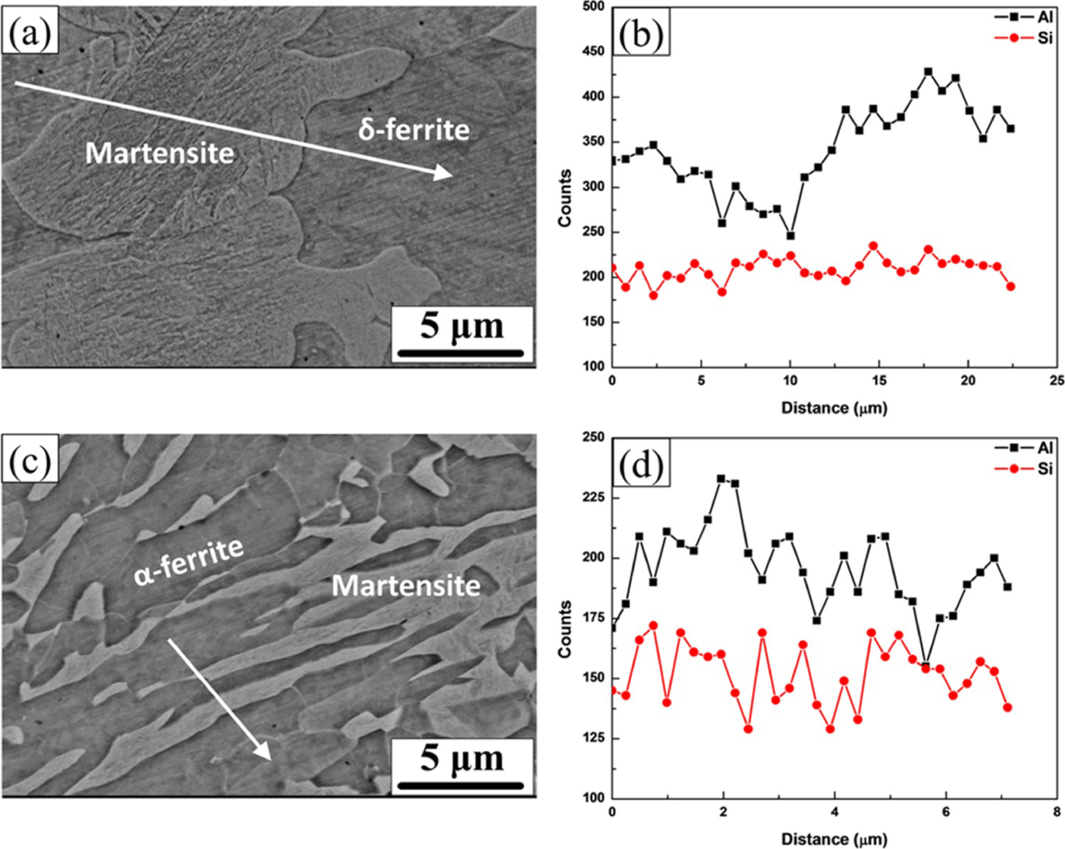
It is important to confirm that it is indeed the addition of Al in the weld zone that leads to the formation of the ferrite phase. Figure 21 (a,b) and (c,d) show the Energy Dispersive X-Ray Spectroscopy (EDX) analysis of the FZ in the ARW and ARWHS condition, respectively. The line-scans confirm that there is a spike in the Al-content when moving from the martensite phase to the ferrite phase which suggests that the formation of the ferrite phase is directly related to the local concentration of Al at the given site.
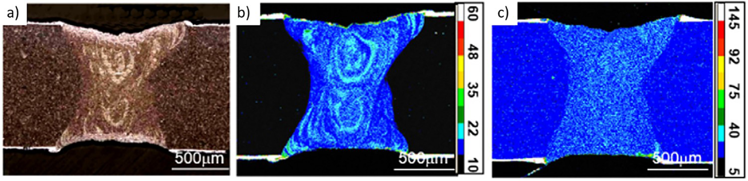
Furthermore, elemental mapping with an electron probe micro-analyzer (EPMA) was used to confirm that the ferrite phase has a high local concentration of Al as shown in Figure 22(a,b). On average, it has been shown that the local Al-wt-% in the ferrite phase in the ARWHS condition ranges from about 1.7–2.5% [26].
Ferrite Distribution in the Weld Zone
The ferrite location in the ARW condition has been shown to be concentrated along the fusion boundary [26]. The Marangoni convection flow can be used to explain the flow of material in the molten weld pool during welding. The flow in a molten weld pool is a function of the surface tension (γ) between the phases and the temperature (T) as shown in Figure 23. The addition of aluminium into the weld decreases the temperature coefficient of surface tension (i.e. is negative) which implies that the molten material inside the weld pool flows from the centre of the weld to the boundary as shown in Figure 23 (b) [64].
Schematic of fluid flow in a molten weld pool showing that when (a)
 is negative (b) molten material inside the weld pool flows from the center of the weld to the boundary and when (c)
 is positive (d) molten material inside the weld pool flows from the boundary to the center of the weld [65].
As Fe and Al both have a negative temperature coefficient of surface tension, the convection circulation in the molten weld pool is such that liquid metal flows from the centre of the weld where the temperature of the system is at a maximum due to the presence of the keyhole to the weld boundary where the temperature is at the lowest [66]. This temperature differential provides the driving force that leads to the fluid flow pattern shown by the red arrows in Figure 24. Therefore, it can be argued that the molten Al–Si coating flows into the weld along the fusion boundary as it is sucked in due to the fluid flow driven by the Marangoni effect, and due to the extremely high cooling (∼10,000°C) during laser welding, it becomes trapped as the molten weld pool quickly solidifies leading to the formation of network-like δ-ferrite that can be clearly seen along the fusion boundary in Figure 19 (d) [67].
Marangoni Convection Flow in a molten weld pool showing that molten material flows from the centre of the weld to the boundary. From Kou [68]. Reprinted with permission from John Wiley and Sons.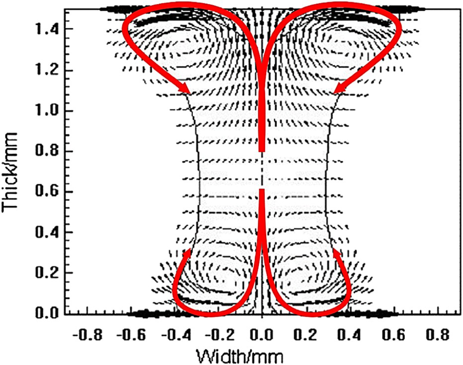
It was noted by Saha et al. that a relatively higher Al-content is observed in the ARW condition compared to ARWHS condition because the aluminium is concentrated along the fusion boundary [26]. During the HS process the aluminium has time to diffuse through the weld at the high austenitisation temperature allowing for the Al-content to be more evenly distributed throughout the weld which is why the local Al-content in the ferrite phase was found to be lower in the ARWHS condition [35]. However, Saha notes that the ferrite phase concentration is higher (about 40%) in the ARWHS condition compared to the ARW condition (about 20%) [26]. It has been suggested that the δ-ferrite phase growth during laser welding in the ARW condition is limited and kept in check due to the large compressive stress imposed on it by the martensite plate formation and growth [69]. However, during austenitisation, the martensite decomposes, relieving the compressive stress which leads to the formation of a more abundant unstressed α-ferrite phase by way of recrystallisation. Therefore, as the ferrite content in the weld increases, the weld becomes softer, and the strength of the weld decreases.
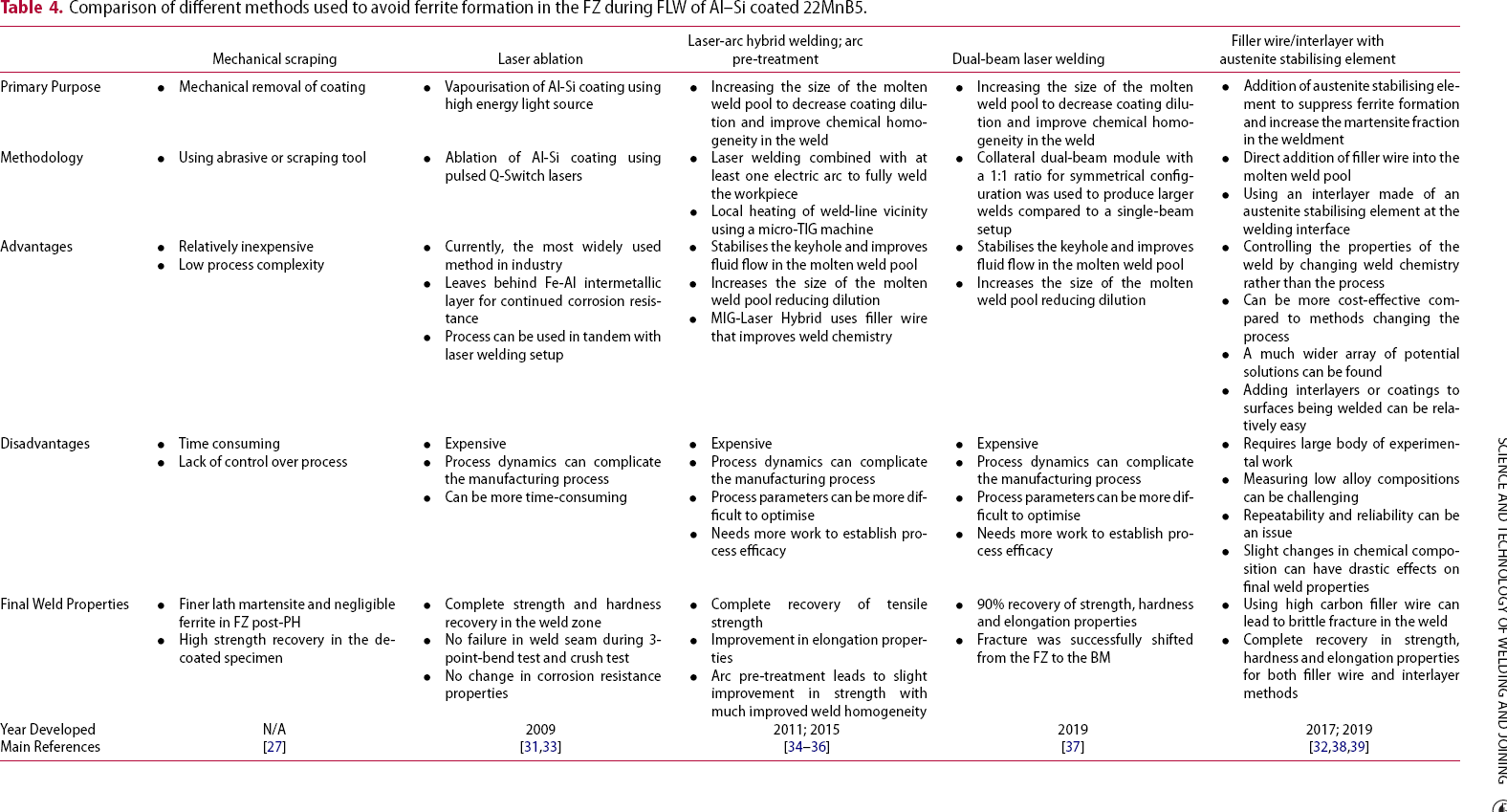
Possible solutions to avoid ferrite formation in the weld zone
Comparison of different methods used to avoid ferrite formation in the FZ during FLW of Al–Si coated 22MnB5.
Fibre laser welding of Zn-coated 22MnB5 PHS
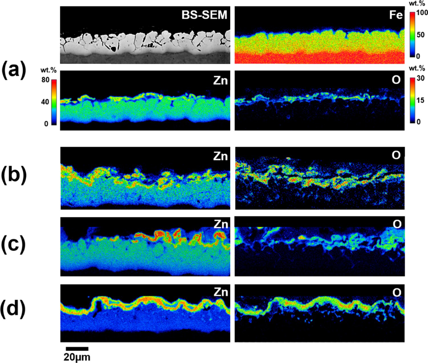
As discussed earlier, due to the issues related to laser beam welding of the mainstream Al–Si coating, researchers have considered using alternative coating systems to protect the 22MnB5 TWBs against severe oxidation and decarburisation during the heat-treatment stage of press-hardening. The most popular alternative coatings of choice have been found to be Zn-based. However, the applied Zn-coating undergoes substantial microstructural evolution and oxidation during the austenitisation portion of the direct HS process. The recent study by Razmpoosh et al. [23] has shown that GA-coating evolution during press-hardening can significantly influence the laser welding process. It has been observed that after heat-treatment, the initial GA-coating evolves into a combination of a Fe-Zn diffusion layer (α-Fe(Zn)) and a ZnO film as shown in Figure 25. It has been reported that the thickness of the diffusion layer and its Zn-content highly depends on the heat-treatment conditions (i.e. overall soaking temperature and time) [23]. Although heat-treatment at a relatively lower temperature such as 860°C results in a linear growth rate of the diffusion layer leading to a subsequent reduction in Zn-content, the diffusion layer evolution behaviour (coating thickness and its Zn-content) changes drastically at higher temperatures (e.g. 900°C). This happens primarily due to the competition between severe Zn-oxidation and Fe-Zn interdiffusion at higher temperatures. Additionally, it has been shown that the initial GA-coating weight determines the final diffusion layer thickness post HS [23].
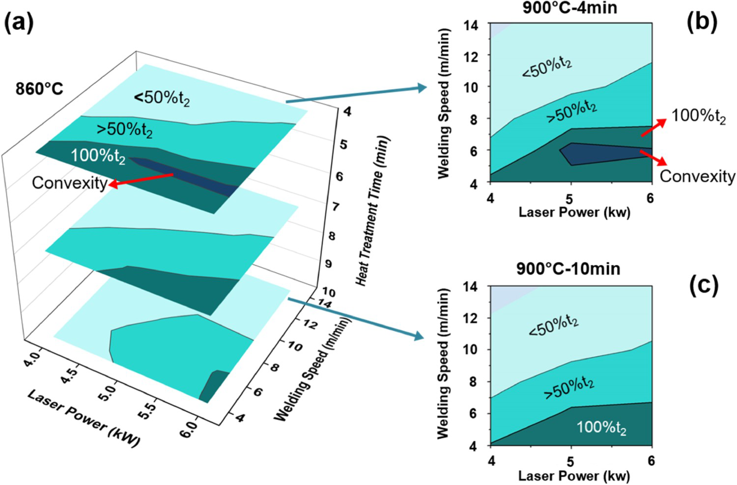
The varying evolution of the coating thickness and the associated Zn-content of the diffusion layer after HS affects laser lap welding behaviour of 22MnB5 PHS. Accordingly, it can be seen that the sensitivity of the laser process window to heat-treatment time is maximised in the case of low temperature of heat-treatment (i.e. 860°C), where full-penetration laser beam welds are achieved at higher heat-input welding conditions (i.e. higher laser power and lower welding speed) with increasing heat-treatment time as shown in Figure 26. However, at higher heat-treatment temperatures ∼900°C, the sensitivity of the laser process window to heat-treatment time drastically decreases [23]. This is attributed mainly to the fact that severe-oxidation at high temperature competes with the expected Fe-Zn inter-diffusion. It is noteworthy that sandblasting after HS takes out Zn (in the form of ZnO) from the material to be welded; therefore, the detrimental effects of the presence of vapourised Zn on the laser beam would be reduced. The sensitivity of laser process window to that of the Zn-coating is also highlighted elsewhere [40] where it is reported that the laser beam welding of a relatively heavier Zn coating requires higher heat-input (i.e. higher laser powers and lower welding speeds). Additionally, a relatively heavier Zn coating makes the process window narrower. The observed process window shift is attributed to the laser-Zn plasma interaction which results in more dissipation of laser energy leading to a lower depth of penetration. In addition to the detrimental effects of the laser-Zn plasma interaction, excessive Zn vapour during FLW leads to a turbulent keyhole which causes material ejection from the melt pool causing concavity in the FZ and further shifting the process window [40].
Although laser beam welding of Zn-coated 22MnB5 PHS seems less problematic in terms of coating mixing into FZ compared to the Al–Si-coated counterpart, a recent study [40] shows that the presence of very low tensile stresses (less than or equal to the yield strength of 22MnB5 PHS in the AR condition) can induce LME cracks during welding. Over the past few years, production of TWBs has emerged as an efficient technique to reach the weight-reduction goals in the automotive industry. This requires sound laser welds of 22MnB5 PHS before the HS stage of the TWB production. However, recent studies have shown the possibility of LME-induced cracking during the welding of TWBs. Indeed, a very low stress level is necessary for LME cracking which can be readily reached by a clamping system fault during welding (e.g. the common problem of misaligned clamping fixtures).
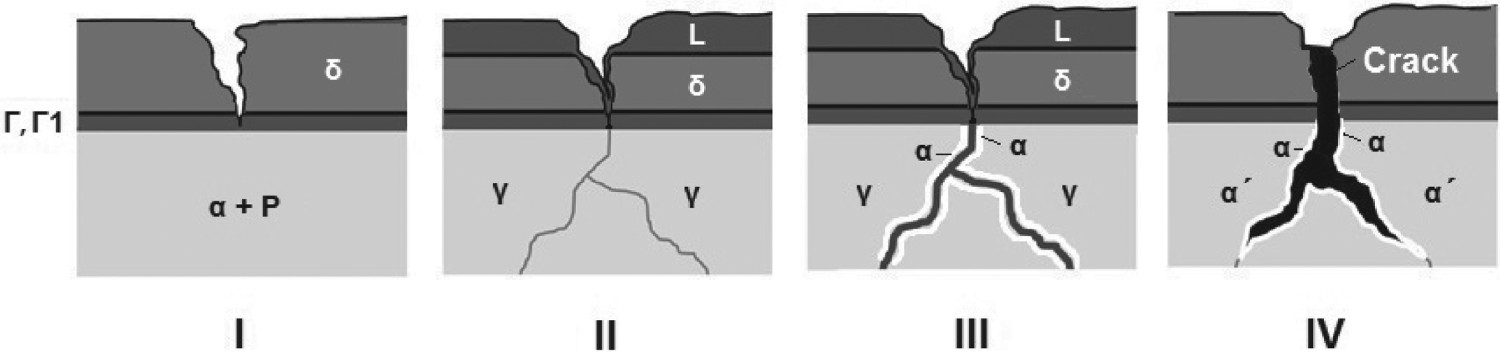
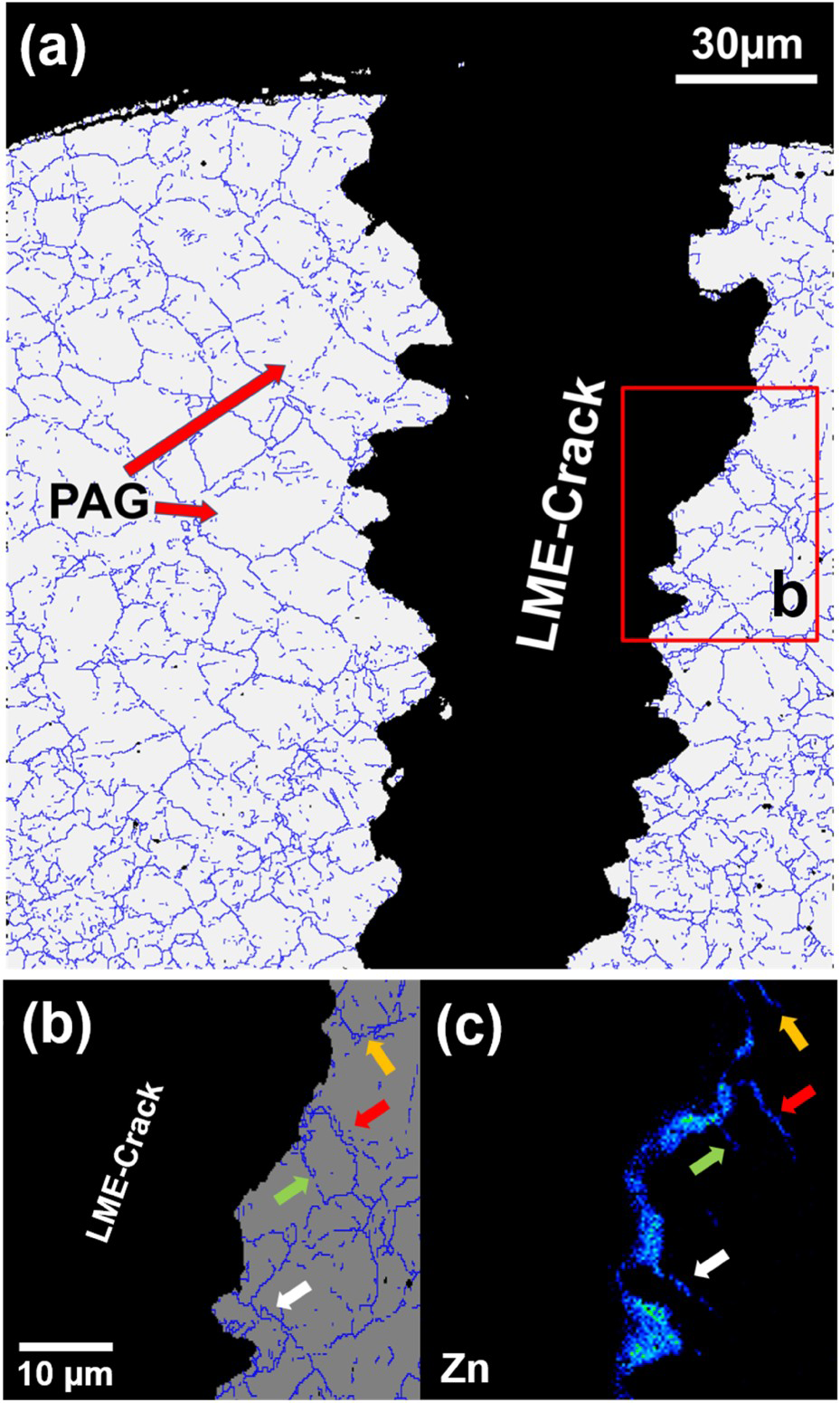
It is reported that during laser welding, the partial melting of the applied GA-coating (Fe-Zn δ and Γ/Γ1 phases) causes it to penetrate the prior austenite grain boundaries within the upper-critical HAZ (Figure 27) [40]. The presence of liquid-Zn along the grain boundaries results in decohesion and rapid cracking as shown in Figure 28 (a). Furthermore, the excessive Zn that penetrates the austenite grain boundaries stabilises the ferrite phase which assists the grain boundary decohesion and subsequent cracking. Kang et al. [71] indicated that high-temperature tensile testing of Zn-coated 22MnB5 steel at 850°C leads to a ductility loss from 35% in the uncoated condition to about 9% in the Zn-coated condition. These results demonstrate potential Zn-related LME of Zn-coated PHS when subjected to high-temperature processes (e.g. welding or HS) under a given magnitude of applied tensile stress. However, it has been suggested that LME-cracking can be successfully avoided through longer austenitisation times [41] which leads to the growth of an α-Fe(Zn) layer where the dilution of Zn reduces its availability for embrittlement. In this case, even under the adequate applied tensile stress, the crack cannot propagate into the steel substrate due to the tip of the crack being blunted by the growth of the α-Fe(Zn) layer [41].
Conclusions
HS technology has transformed the automotive industry by simultaneously making vehicles more efficient and making them safer with much improved crashworthiness qualities – primarily, due to the increase in usage of PHSs in building the BIW frame of newer vehicles. This work has looked closely at the 22MnB5 grade PHS, its mechanical and metallurgical properties, as well as the different types of coatings that are used to protect the steel from corrosion and decarburization. From the study of these various coatings it was observed that there is no perfect coating that has been developed for 22MnB5 PHS as all of the different types of coatings in use today come with their respective set of challenges depending on the conditions that these coatings are being used in.
In this literature review, the direct HS method to produce parts with tailored properties known as TWBs has been closely studied. An in-depth analysis of the use of TWBs in industry and the problems that arise with the laser welding of the different types of coated 22MnB5 grade PHS have been discussed. By doing a thorough review of the literature on the matter, it was deduced that the cause for issues with the mechanical properties of laser welded joints of Al–Si coated 22MnB5 is the dilution of the coating into the molten weld pool. An increase in Al-content in the weld leads to a direct increase in the ferrite phase concentration found in the FZ microstructure which has been shown to negatively impact the hardness, strength and elongation properties of the weldment. A detailed and up-to-date comparison of possible solutions to the problem of FZ softening due to an increasing ferrite content was presented. Although, there are existing solutions being used in industry today that fully solve the problem of FZ softening due to the presence of ferrite, these solutions are: not sufficiently cost-effective, encountering serious technological difficulties, or the underlying physics or chemistry of the proposed solutions has not been entirely understood which calls for future studies.
The Zn-coated 22MnB5 is susceptible to LME during HS. However, LME can be efficiently prevented through process-variable modifications. Apart from the embrittlement risk, the applied Zn-coating evolution during the heat treatment stage of HS significantly affects the welding process window and this is attributed to the Zn-Fe interdiffusion and severe Zn-oxidation at elevated temperatures.
It can be concluded from the findings of the present work that even though HS technology has been in use for some time, there are still problems with the process that demand solutions. There is no doubt that the process has come a long way since its inception, but the technology is far removed from being perfect and there is still a lot more room for improvement as discussed in the following section.
Future work and recommendations
There are two main areas of improvement that can be highlighted as a consequence of this work. Firstly, we note that in terms of the various coatings being used to protect 22MnB5 PHS, all of them have very serious limitations in regard to their usage. None of the coatings considered in this work provide a universal solution to the problem of corrosion and oxidation protection. In fact, almost all of the mechanical and metallurgical issues associated with 22MnB5 PHS stem from the interaction of the coating with the substrate during the HS process – namely, LME cracking when using Zn-based coatings – or during the laser welding process where the dilution of the Al–Si coating leads to severe FZ softening. Following from that, it is recognised that there is work yet to be done in developing new coating technologies and/or improving the state of the art of existing coating technologies for HS applications.
Secondly, despite the existence of fully functional solutions to the problem of weld softening in TWBs due to the dilution of the Al–Si coating into the FZ during laser welding, there exists a space in which newer and better solutions can be found that are more practical, more affordable and easier to implement than the solutions currently being used. There is room to develop process methodologies in which in-situ coating ablation can be achieved as a consequence of the reaction between the laser and the coating surface. This can be achieved by modifying the surface properties of the coating to change its emissivity properties or by adding an additional coating that creates a reaction with the existing coating upon contact with the laser by way of which the problematic coating can be removed. Furthermore, it can be noted that careful alterations in the chemical composition of the FZ by adding different elements will give much better insight into how the mechanical and metallurgical properties of the weld zone can be controlled. A study of this sort may pave the way for future BM engineering, or it may open the door to developing newer coating technologies as our collective understanding of the material science that governs this problem improves. In the short-run, it may just help to solve the problem of FZ softening due to the dilution of the coating into the molten weld pool.
Footnotes
Acknowledgements
This work would not have been possible without the support of the Natural Sciences and Engineering Research Council (NSERC) of Canada and the Canada Research Chairs (CRC) Program.
Disclosure statement
No potential conflict of interest was reported by the author(s).
Correction Statement
This article has been republished with minor changes. These changes do not impact the academic content of the article.